Moen 12443 Series User manual

MB082E12443, 12444, 12448, 12451,
T909, T926, T928, 6980 SERIES
INSTALLATION INSTRUCTIONS
MODE D'INSTALLATION
TOP OF
FINISHED
SURFACE
HAUT DE
SURFACE FINI
2-5/8"
2-5/8"
PUTTY
(Not Supplied)
MASTIC
(Pas fourni)
10" Centers
entr'axes de 10"
CONCENTRIX
INSERT HANDLE
(Inserts not furnished)
POIGNÉE INSÉRÉE
CONCENTRIX
(Insérée pas fourni)
ACRYLIC
KNOB HANDLE
POIGNÉE
ACRYLIQUE TRANSPARENT
DECK-MOUNT WIDESPREAD ROMAN TUB
ROBINET A POIGNEES ELOIGNEES POUR MONTAGE
HORIZONTAL POUR BAIN ROMAN
®
Before turning water on during either rough-in or trim-out, make sure that cartridge retainer nuts are in place. The cartridges and retainer nuts were
properly installed and tested before leaving the factory. Although it is unlikely, it is nevertheless possible that through the handling of the valve by any
number of persons the retainer nuts may not be properly installed. This should be carefully checked at time of rough-in and trim-out. If retainer nuts
are not properly installed, water pressure could force the cartridge out of the casting. Personal injury or water damage to the premises could result.
Avant d’ouvrir l’alimentation en eau, soit pendant la pose de la plomberie brute ou pendant la pose de la garniture, s’assurer que la bague de retenue
estenplace.Lacartoucheetlabaguederetenuedecartoucheontetecorrectementinstalleeettestesavantdequitterl'usine.Quoiqu'improbable,ilest
neanmoins possible que par suite de la manipulation de la valve par plusieurs personnes, la bague de rentenue ait ete deplacee. Ceci devra etre
soigneusement verifie lors de la pose de la plomberie brute et lors de la pose la garniture. Si la bague de retenue n'est pas correctement installee, la
pression d'eau pourrait deloger le cartouche du bati de robinet. Ceci pourrait causer des blessures corporelles ou des degats par l'eau sur les lieux.
FERMER l’alimentation en eau avant de démonter la soupape. Ouvrir les deux poignée de la soupape pour
libérer la pression d’eau et s’assurer que la pression d’eau est COMPLETEMENT coupée.
Always turn water off before disassembling the valve. Open valve handle to relieve water pressure and to insure
that complete water shut-off has been accomplished.
CAUTION:
REMARQUE:
NOTE: VALVE BODIES
ARE NOT SUPPLIED WITH
TRIM PACKAGES.
REMARQUE: BATIS DES
SOUPAPES NE SONT PAS
FOURNIS AVEC LA
TROUSSE DE LA
GARNITURES.

1. For adjustable height valve body installation: With a pipe cutter, cut the mounting shank to required height (1" - 1-1/4" above finished deck).
CAUTION: REMOVE BURRS AND BEVEL END OF SHANK. FAILURE TO DO SO MAY RESULT IN DAMAGED SPOUT O-RING DURING SPOUT
INSTALLATION.
2. Install set screw into tub spout.
3. Apply 3/8" of plumber's putty (not furnished) on the finished tub base around the mounting shank.
4. Install roll pin into base of tub spout. CAUTION: SEE TEMPLATE ON PAGE 4 FOR ROLL PIN LOCATION. Drill a 7/32" hole into tub base. Install
tub spout with roll pin installed onto mounting shank. Press down until it becomes flush with finished tub base.
5. With tub spout and roll pin in postion, tighten set screw with hex wrench and install plug button.
Ouvrir l'emballage de la garniture et vérifier si toutes les pièces requises pour l'installation du bec verseur sont incluses:
1 bec 1 cheville cylindrique
1 vis de pression 2 moyeux de poinées/2 poignées (avec capuchon de poignées)
2 rosaces 4 vis (deux long, deux court)
1. Avec un coupe-tuyaux, couper la tige de montage a la hauteur desirée. REMARQUE: ENLEVER ELS EBARBURES ET BISEAUTER L'EXTREMITE
DE LA TIGE. CETTE OPERATION EMPECHERA D'ENDOMMAGE L'ANNEAU EN "O" LORS DE L'INSTALLATION DU BEC.
2. Installer la vis de pression àl'intérieur du bec.
3. Appliquer un collier de 3/8 po. de mastic de plombier (non-inclus) sur la base de la baignoire et autour de la tige de montage.
4. Installer la cheville cylindrique àl'intérieur de la base du bec de baignoire. REMARQUE: VOIR GABARIT A LA PAGE 4 POUR L'EMPLACEMENT
DE LA CHEVILLE CYLINDRIQUE. Percer un trou de 7/32 po. dans la base de la baignoire. Installer le bec de baignoire avec la cheville cylindrique
sur la tige de montage. Presser jusqu'àce que le bec soit de niveau avec la base de la baignoire.
5. En maintenant le bec de baignoire et la cheville cylindrique en position, visser la vis de pression avec une cléhexagonale et installer bouchon de bec.
Open trim package to see that all parts for the tub filler
installation have been enclosed:
1 spout 1 roll pin
1 set screw 2 handle hubs or 2 knobs (with inserts)
2 escutcheons 4 screws (2 long, 2 short)
Flushing-Rinçage
MB082E
Tub Spout Installation
Installation du bec
de baignoire
3-9/16" (small spout)
4-15/32" (large spout)
7-1/8" (small spout)
10" (large spout)
TUB SPOUT
BEC DE BAIGNOIRE
SET SCREW
VIS DE
PRESSION
O-RING
ANNEAU EN "O"
STREAM STRAIGHTENER
REGULATEUR
DE DEBIT
PUTTY (NOT SUPPLIED)
MASTIC DE PLOMBIER (NON-
INCLUS)
MOUNTING SHANK
TIGE DE MONTAGE
PLUG
BUTTON
BOUCHON
DE BEC
TOP OF FINISHED
SURFACE
HAUT DE SUFACE FINI
ROLLPIN
CHEVILLE CYLINDRIQUE
1" - 1-1/4"
IMPORTANT: Pipe chips, sand, stones and other solids found in new and renovated plumbing can damage the sealing surfaces of the cartridge and
cause a leak. To avoid damage, DO NOT TURN ON THE SUPPLY VALVES until instructed below.
1. After installing and connecting your new faucet, open both hot and cold cartridges.
2. Turn on both hot and cold water supply valves and allow the water to run for 15 seconds.
3. Turn off the water. Unscrew stream straightener from spout and remove any trapped debris.
4. Replace the stream straightener. Check system for leaks.
IMPORTANT: Les débris de tuyauterie, le sable, la pierraille et autres matériaux qui se trouvent dans la plomberie neuve et rénovée peut endommager
les surfaces d'éntanchéitéde la cartouche et causer une fuite. Pour éliminer ces risques, NE PAS FAIRE FONCTIONNER LA SOUPAPE avant d'avoir
complétéces instructions.
1. Apres avoir installéet raccordévotre nouveau robinet. Ouvrir les cartouches.
2. Ouvrir les soupapes d'arrêt et laisse s'écouler pendant 15 secondes.
3. Couper l'eau. Dévisser l'adapteur du bec et retirer tous les débris de tuyauterie.
4. Replacer l'aérateur. Vérifier si le système a des fuites.

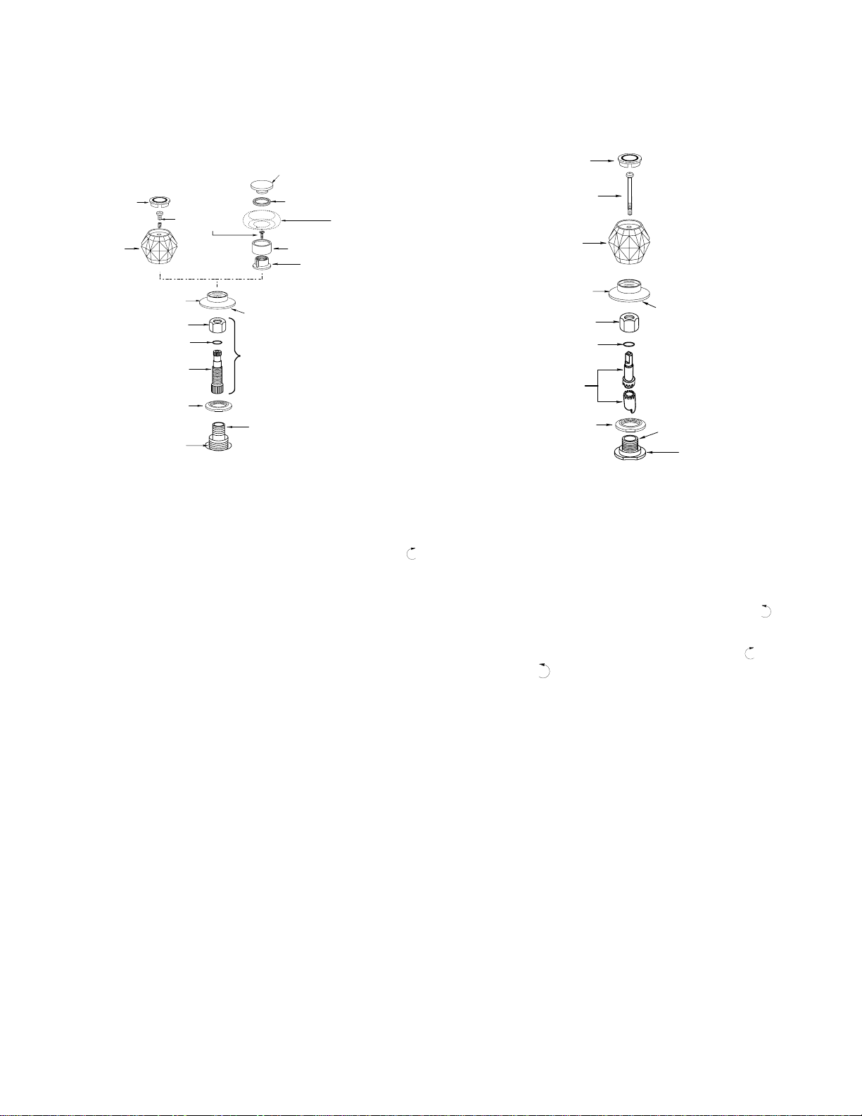
Montage de la garniture
Non-adjustable Height Valve Body Installation.
Installation du bâti de soupape a hauteur non-adjustable.
1. Place a 3/8" bead of plumber's putty to the underside of the escutcheon
then screw the escutcheon onto the escutcheon adjuster.
2. Install handle adapter, O-ring and compression nut.
3. KNOB STYLE: Temporarily place handle on handle adapter so that the
adapter engages handle socket. Rotate HOT SIDE handle clockwise
until it stops. This assures that both cartridges are in the OFF positoin.
Adjustments can be made by removing the compression nut and lifting
the handle adapter to index clockwise (or counterclockwise to properly
orient handles. Replace compession nut.
4. Insert handle screw and tighten securely. If handle rotation is reversed,
turn stem extension stop 180°and re-install.
5. CONCENTRIX STYLE: Place concentrix handle insert (not furnished)
over insert handle adapter. Fit gasketr into handle cap recess, secure
with handle cap. You are now ready to turn water back on. Check
complete system for leaks.
1. Appliquer un collier de mastic de plombier de 3/8 po autour la base de la
rosace et visser la rosace sur le réguleur de rosace.
2. Installerl'adaptateurdepoignée, l'anneauen"O" etl'écroudecompres-
sion.
3. POIGNEE STYLE: Placer temporairement la poignée sur l'adaptateur
de poignée pour que l'adaptateur s'engage dans le manchon de la
poignée. TournerlapoignéeduCÔTÉCHAUDdanslesensdesaiguilles
d'une montre jusqu'àce qu'elle bute. Les deux cartouches sont en
position FERMÉE, les réglages peuvent être effectués en enlevant
l'écrou de compression et en soulevant l'adaptateur pour orienter les
poignéescorrectement(danslesensdesaiguillesd'unemontreoudans
le sens contraire selon le capuchon indicateur).
4. Insérerla visdepoignéeetserrer fermement. Sila rotationestinversée,
tourner l'arrét de la rallonge de tige sur 180°et installer ànouveau.
5. CONCENTRIX STYLE: Placer la garniture de poignée Concentrix (non
comprise) pas dessus l'adaptateur pour garniture de poignée. Fixer le
support dans le renfoncement du capuchon de poignée. Serrer avec le
capuchondepoignée.Vouspouvez ouvrirl'alimentationeneau. Vérifier
si le système a des fuites.
H
ESCUTCHEON
ROSACE
COMPRESSION NUT
ECROU DE COMPRESSION
O-RING
ANNEAU EN "O"
HANDLE ADAPTER
ADAPTATEUR DE POIGNEE
LOCKNUT
CONTRE ECROU (HAUT)
ESCUTCHEON ADJUSTER
REGLEUR DE ROSACE
PUTTY
MASTIC
HANDLE KNOB
POIGNEE
HANDLE SCREW
VIS DE POIGNEE
HANDLE INSERT
CAPUCHON DE POIGNEE
HANDLE CAP
CAPUCHON
INDICATEUR
CONCENTRIX
HANDLE INSERT
PIÉCE INSÉRÉE CONCENTRIX
HANDLE SKIRT
JUPE DE POIGNÉE
HANDLE HUB
ENJOLIVEUR DE POIGNÉE
STEM EXTENSION
RALLONGE DE TIGE
GASKET
LE SUPPORT
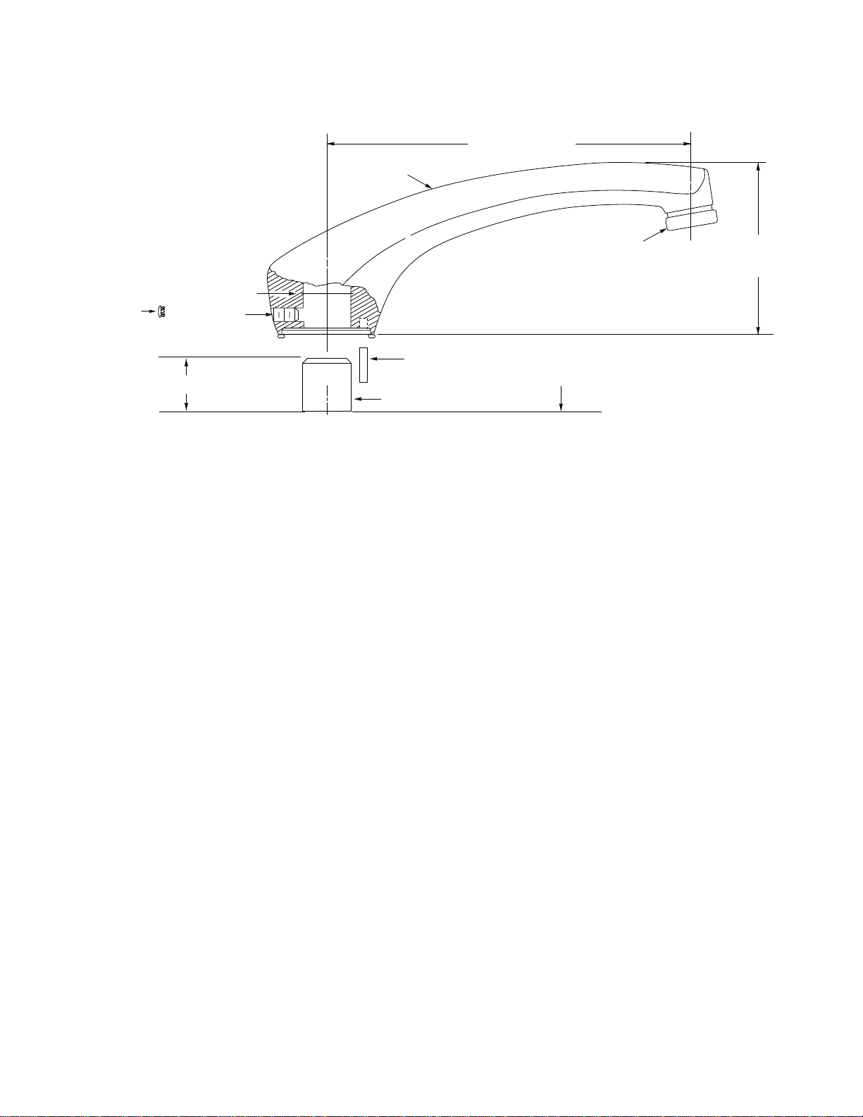
For proper escutcheon adjust-
ment, place O-ring onto handle
adapter FIRST. Then HAND
TIGHTEN compression nut.
Pour ajuster correctement la
rosace,placerD"ABORDl'anneau
en"O"surl'adaptateurdepoignée.
Ensuite SERRER A LA MAIN
l'écrou de compression.
H
ESCUTCHEON
ROSACE
COMPRESSION NUT
ECROU DE COMPRESSION
O-RING
ANNEAU EN "O"
HANDLE ADAPTER
ADAPTATEUR DE POIGNEE
LOCKNUT
CONTRE ECROU (HAUT)
HANDLE KNOB
POIGNEE
HANDLE SCREW
VIS DE POIGNEE
HANDLE INSERT
CAPUCHON DE POIGNEE
HANDLE ADAPTER
ADAPTATEUR DE POIGNEE
PUTTY
MASTIC
VALVE BODY
BATI DE SOUPAPE
CAUTION: Failure to follow these instructions can cause a faulty
installation or damage the new cartridge.
1. Apply 1 3/8" bead of plumber's putty to the underside of the escutcheon
and screw the escutcheon onto valve body.
2. With cartridge nut removed, assemble the handle adapter and handle to
the new cartridge and tighten handle screw. This will aid in locating the
cartridge properly in the valve body.
3. Drop the cartridge into the valve body and press down.
4. Now press down firmly while rotating handle counterclockwise . This
will align the "KEY" on the cartridge with the "NOTCH" in the valve body.
Whenthekeyentersthenotch you will feel it drop in and the cartridge will
be in place. To be certain, rotate the handle clockwise and then
counterclockwise withgentleforce. You should feelthehandle stop in
both directions. If so, the cartridge is in place. Do not turn on the water
yet.
5. Unscrew handle screw and remove handle in order to replace the
cartridgenut. Besureo-ringisinsidecartridgenut. Replacethecartridge
nut - do not cross thread - and tighten firmly.
Installation is complete. Flushing is required.
ADVERTISSEMENT: Le fait de nes pas suivre ces instructions pourrait
endommager la cartouche au point qu'elle ne puisse être réparée.
1. Appliquer un collier de mastic de plombier de 3/8 po autour la base de la
rosace et visser la rosace au bâti de soupape.
2. L'écrou de cartouche enlecvé, installer l'adaptateur de poignée àla
nouvelle cartouche et serrer avec la vis de poignée. Ceci permettra de
situer la cartouche dans le bâti de la soupape.
3. Glisser la cartouche dans le bâti de soupape et pousser.
4. Pousserfermementsurlapoignéeentournantdanslesenscontrairedes
aiguilles d'une montre. Ceci alignera la «CLEF»sur la cartouche avec
l'«ENCOCHE»dans le bâti de soupape. Lorsque la clef entre dans
l'encoche,lacartoucheglisseenposition. Tournerdoucementlapoignée
dans le sens des aiguilles d'une montre et vive-versa pour s'en assurer.
La poignée devrait buter dans les deux directions. Si c'est le cas, la
cartouche est correctement installée. Ne pas encore ouvrir l'eau.
5. Dévisser la vis de poignée et enlever la poignée pout pouboit trplsvrt
l'écrou de cartouche. S'assurer que l'anneau en «O»est àl'intérieur
l'écroudecartouche. Replacerl'écroudecartouche-nepasentrecroiser
les filets - et serrer fermement.
L'installationestmaintenant complétée. Lerinçagedu robinet estprimordial.
To assemble trim package
Adjustable Height Valve Body Installation
Installation du bâti de soupape a hauteur ajustable

TEMPLATE FOR ROLL PIN LOCATION ROMAN TUB SPOUT
GARBARIT POUR L'EMPLACEMENT DE LA CHEVILLE CYLINDRIQUE
Call our HELPLINE 8:30 am to 4:30 pm EST for answers to any
product , installation, replacement parts, or warranty questions.
in the U.S., (800) 321-6636; Ontario and Quebec, (800) 465-
0279; Toronto, (416) 829-3400; Rest of Canada, (800) 465-
6130. Ask for product service.
Téléphone ànotre LIGNE D'AIDE de 8.30 à16.30 HNE, afin
d'obtenir les résponses àn'importe quelle question au sujet du
produit,depiecesderechange,deinstallation,oudelagarantie.
enlaE.U.,(800) 321-6636;OntarioetQuebec,(800) 465-6130;
Toronto, (416) 829-3400; Autres provinces, (800) 465-6130.
Demandez le service au produit.
MB082E SEPT 94 25300 Al Moen Drive, North Olmsted, OH. 44070-8022
2816 Bristol Cirle, Oakville, Ontario L4W 1H7 Canada
©Copyright, 1994
Moen Incorporated
Printed in U.S.A.
(FRONT)
(DEVANT)
➤
➤
➤
➤
.730
27/32" DIA.
MOUNTING SHANK
DIAMETRE DE LA TIGE
DE MONTAGE 27/32 PO.
7/32"
DRILLROLL PIN
PERCER UN TROU DE 7/32
PO. POUR LA CHEVILLE
CYLINDRIQUE
®
This manual suits for next models
7
Other Moen Plumbing Product manuals

Moen
Moen Antique Brass 4962A Setup guide

Moen
Moen T6620BN User manual

Moen
Moen 84294 User manual

Moen
Moen L2351 Series User manual

Moen
Moen ICON T964BB User manual

Moen
Moen T9343 Series User manual

Moen
Moen 7175 User manual

Moen
Moen L82680 User manual

Moen
Moen Muirfield 84000 series User manual

Moen
Moen ioDIGITAL T9322 User manual

Moen
Moen INS191 User manual

Moen
Moen Waterhill S411BN Setup guide

Moen
Moen TUB AND SHOWER VALVES 2290 User manual

Moen
Moen CA87009 Series User manual

Moen
Moen Kingsley T6103AN Setup guide

Moen
Moen 67905 Operational manual

Moen
Moen 7560 Operational manual

Moen
Moen 82403 User manual

Moen
Moen Waterhill S9204 User manual

Moen
Moen MONTICELLO 84437ORB Setup guide