manuals.online logo
Brands
  1. Home
  2. •
  3. Brands
  4. •
  5. MOFLASH SIGNALLING
  6. •
  7. Marine Equipment
  8. •
  9. MOFLASH SIGNALLING AE100M Series Manual

MOFLASH SIGNALLING AE100M Series Manual

INSTALLATION &
TECHNICAL INFORMATION
PLEASE READ PRIOR TO INSTALLATION
Website: www.moash.com Email: technical@moash.co.uk
APPROVED AND
CONFORMITIES
Alarm Stages
The alarm stages are set as follows:
Refer to Tone Selection Sheet ref: S00600 for Tone Selection and Volume Control.
Sound Pause Option
Briey close the loop between ‘S0 – Dly’ for 1 second minimum each time to give the
required pause interval. The sound automatically restarts at the end of the interval.
5.0 End of Line Monitoring
An end of line monitoring diode or an end of line monitoring resistor can be
connected across the 24V+ and 0 terminals. Resistor values for the End of Line will be
determined by the customer with a minimum value of 1.2kΩ
6.0 Maintenance
Little or no maintenance is required during the normal working life of the product. The
Moash Exd enclosures are resistant to most acids, alkalis and chemicals and have been
designed to withstand severe weather conditions. However it is suggested that to avoid
the possibility of a potential electrostatic charge build up, the exterior of the product is
periodically wiped down with a clean damp cloth. At this point a visual inspection is
recommended to ensure that the product is in good working order and no damage has been
sustained during its normal operation.
7.0 Conditions for Safety Use
i) This apparatus is suitable to be used only in ambient temperature as stated below:
ii) Other than product manufacturer, painting and surface nishing are not permitted
by the third party.
iii) When used in dusty atmosphere, ameproof cable entry devices or stopping plugs
have to be selected and installed carefully in order to maintain the IP rating (IP66)
of the product.
Moash part code AE100M-S00599-Issue 2
AE100M Series - Weatherproof Sounder
PC - Polycarbonate
AUDIBLE SIGNALLING DEVICE
Type Ambient Temp
AE100M -400C to +700C
Stage Apply Power To Termination Connection Tone
1L & N -No sound
2L & N S0 to S1 (Factory pre-set) Set by DIP SW1
3L & N S0 to S2 Set by DIP SW2
4L & N S0 to S1 &S2 Set by DIP SW3
No of times Pause Interval
1 1 minute
25 minute
310 minutes - Closing the loop again for 1 second during this interval
automatically restores the sound.
1.0 Introduction
The AE100M series is a weatherproof electronic sounder designed for use in harsh
environmental conditions and is manufactured from UV Stable Polycarbonate
plastic. The sounder has a 3 stage alarm option & has 60 tone options that can be
pre-selected. A stainless steel mounting bracket allows the unit to be pivoted through
180 degrees to maximise directional audibility.
2.0 Voltage Classications
The AE100M is available for the following voltage ranges:
AE100M-02 – 12-48v DC or AE100M-04 – 100-240V AC
3.0 Installation
General Requirements
• Installation must be carried out in accordance with the latest codes and regulations
by a qualied electrician.
• Ensure power is disconnected prior to installation or maintenance.
• Environmental exposure conditions during installation should be dry, not moist
or wet.
• Avoid mounting the sounder where it will be subject to excessive vibration.
Location
The location of the unit should be made with due regard to the area over which the
sounder warning signal must be audible. The unit should only be xed to services
that can carry the weight of the unit.
Mounting
The unit mounts via a ‘U’ shaped stainless steel bracket by using one 8mm
dia and two 6mm dia bolt holes in the centre of the bracket (see picture 1). The
alignment and positions can be adjusted by loosening the two M6 screws, which
fasten the stainless steel bracket to the sounder. The sounder should be positioned
such that dust, debris or water cannot enter into the horn opening.
4.0 Wiring
General Requirement
Moash recommends that all cables and cores should be fully identied (suggest
using cable from 2.0 to 2.5 mm²). Ensure that all nuts, bolts and screws are secured.
Ensure that only the right and certied cable glands are used and earthed correctly.
Ensure that only the right and certied stopping plugs are used to blank o unused
gland entry points. In order to maintain the IP rating of the product, we recommend
SS316L for this application.
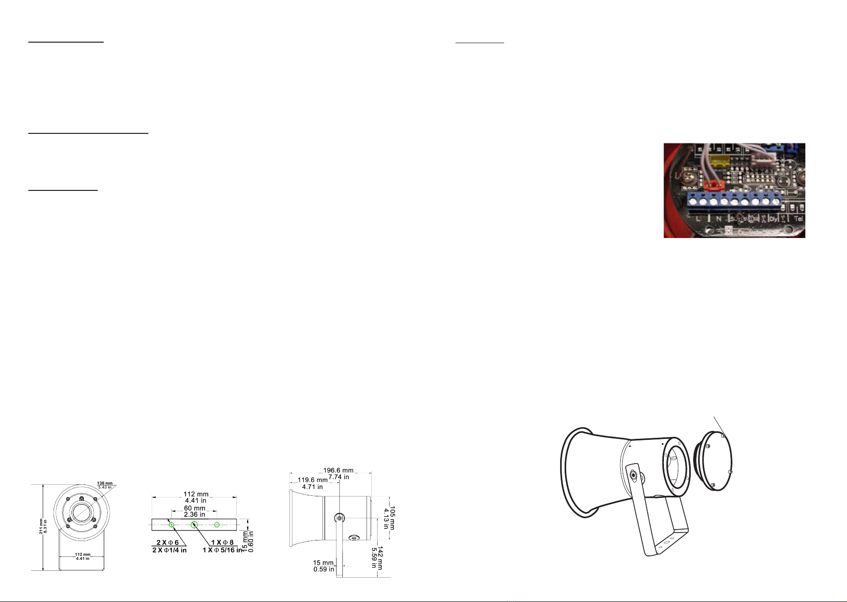
Cable Connection
e cable connection is to terminals on the
PCB located within the enclosure of the
sounder. Cable connection should be carried
out in accordance with relevant technical
requirements (see picture 1)
For AC supply - connect to terminals marked ‘L’ & ‘N’.
For DC supply - connect ‘+’ to ‘L’ and ‘-‘ (0v) to ‘N’.
Alarm stages - terminals ‘S0’ (common) ‘S1 & S2’
(refer to table overleaf). With ‘D’ or ‘Dly’ as the delay function.
Do not connect AC or DC to S0, S1, S2 or D.
Removal of End Cover
Unscrew the four (4) M5 retained hex socket head screw (see diagram 2). Twist
the cover gently clockwise and anti-clockwise, whilst pulling away from the body,
keeping the cover parallel to the body until it comes free. is will allow the cover to
hang on its retaining strap. Before replacing the cover, check the joints are clean and
not damaged, the gasket is retained in its groove.
4 - M5
SOCKET
SCREWS
Picture 1
Diagram 2
Diagram 1

This manual suits for next models

1

Other MOFLASH SIGNALLING Marine Equipment manuals

MOFLASH SIGNALLING SB150-1 Series Manual

MOFLASH SIGNALLING

MOFLASH SIGNALLING SB150-1 Series Manual

MOFLASH SIGNALLING SD125 Series Manual

MOFLASH SIGNALLING

MOFLASH SIGNALLING SD125 Series Manual

MOFLASH SIGNALLING SB150-1 Series Manual

MOFLASH SIGNALLING

MOFLASH SIGNALLING SB150-1 Series Manual

MOFLASH SIGNALLING SB150-1 Series Manual

MOFLASH SIGNALLING

MOFLASH SIGNALLING SB150-1 Series Manual

MOFLASH SIGNALLING AE40M-24R-SB User manual

MOFLASH SIGNALLING

MOFLASH SIGNALLING AE40M-24R-SB User manual

MOFLASH SIGNALLING S00608 Manual

MOFLASH SIGNALLING

MOFLASH SIGNALLING S00608 Manual

MOFLASH SIGNALLING SB150-1 Series User manual

MOFLASH SIGNALLING

MOFLASH SIGNALLING SB150-1 Series User manual

MOFLASH SIGNALLING IS-S-02 Manual

MOFLASH SIGNALLING

MOFLASH SIGNALLING IS-S-02 Manual

Popular Marine Equipment manuals by other brands

Humminbird HELIX GPS installation guide

Humminbird

Humminbird HELIX GPS installation guide

Raymarine ST60 Tridata quick start guide

Raymarine

Raymarine ST60 Tridata quick start guide

Dual SG1 Installation & owner's manual

Dual

Dual SG1 Installation & owner's manual

Simrad ES70 - REV A Reference manual

Simrad

Simrad ES70 - REV A Reference manual

NKE PROCESSOR HR User manual and installation guide

NKE

NKE PROCESSOR HR User manual and installation guide

West Marine 14286801 owner's manual

West Marine

West Marine 14286801 owner's manual

Sleipner MIDI 202 user manual

Sleipner

Sleipner MIDI 202 user manual

E2S E2 C1LD2F Series instruction manual

E2S

E2S E2 C1LD2F Series instruction manual

Pfannenberg DSF 5 Installation and operating instructions

Pfannenberg

Pfannenberg DSF 5 Installation and operating instructions

Veratron VMH 35 user manual

Veratron

Veratron VMH 35 user manual

Grammer AVENTO Sports Line Suspension Kit operating instructions

Grammer

Grammer AVENTO Sports Line Suspension Kit operating instructions

Kongsberg Simrad NISE 3900E installation manual

Kongsberg

Kongsberg Simrad NISE 3900E installation manual

Furuno FCV-1200L Operator's manual

Furuno

Furuno FCV-1200L Operator's manual

Fusion Apollo RA770 owner's manual

Fusion

Fusion Apollo RA770 owner's manual

hyfire HFC-WSW-03 Installation

hyfire

hyfire HFC-WSW-03 Installation

Magnadyne M6100CD Installation and operation manual

Magnadyne

Magnadyne M6100CD Installation and operation manual

Shockwave S5 user manual

Shockwave

Shockwave S5 user manual

Harken Carbo Air 79735 instruction sheet

Harken

Harken Carbo Air 79735 instruction sheet

manuals.online logo
manuals.online logoBrands
  • About & Mission
  • Contact us
  • Privacy Policy
  • Terms and Conditions

Copyright 2025 Manuals.Online. All Rights Reserved.