E2S E2 C1LD2F Series User manual

_______________________________________________________________________________________________________________________________
European Safety Systems Ltd. Impress House, Mansell Road, Acton, London W3 7QH sales@e-2-s.com Tel: +44 (0)208 743 8880
www.e-2-s.com Fax: +44 (0)208 740 4200
Document No. D209-00-511-IS-SC Issue C 13-06-17 Sheet 1 of 8
INSTRUCTION MANUAL
E2xC1LD2R & E2xC1LD2F Combined Sounder & Beacon
For use in Hazardous Locations
1) Warnings
DO NOT OPEN WHEN AN EXPLOSIVE
ATMOSPHERE IS PRESENT
DO NOT OPEN WHEN ENERGISED
POTENTIAL ELECTROSTATIC CHARGING
HAZARD - CLEAN ONLY WITH A DAMP
CLOTH
HIGH VOLTAGE SHOCK HAZARD. WAIT 5
MINUTES AFTER REMOVING POWER
BEFORE OPENING THE ENCLOSURE
Avertissement:
NE PAS OUVRIR UN PRESENCE
D’ATMOSPHERE EXPLOSIVE
NE PAS OUVRIR ENERGIE
DANGER POTENTIEL CHARGE
ÉLECTROSTATIQUE - NETTOYER
UNIQUEMENT AVEC UN CHIFFON HUMIDE
HAUT TENSION, RISK DE CHOC.
ATTENDEZ 5 MINUTES APRES AVOIR
DEBRANCHE L’ALIMENTATION AVANT
D’OUVRIR LA BOITIER
2) Rating & Marking Information
2.1 ATEX / IECEx certification
The E2xC1LD2 combined alarm horn and LED beacon
complies with the following standards:
EN60079-0:2012+A11:2013 / IEC60079-0: ed. 6.0 (2011-06)
EN60079-15:2010 / IEC60079-15: ed. 4.0 (2010-01)
EN60079-31:2014 / IEC60079-31:2013 ed. 2.0 (2013-11)
Certificate No. DEMKO 06ATEX 0421554X
IECEx ULD 14.0012X
The E2xC1LD2 combined alarm horn and LED beacon is
rated as follows:
CE Marking
Zones, Gas / Dust Groups and Temperature
Classification
When connected to an approved system the E2XS1 alarm
horn may be installed in:
Zone 2 explosive gas air mixture not likely to occur
in normal operation, and if it does, it will only exist
for a short time.
Zone 22 explosive dust air mixture not likely to occur
in normal operation, and if it does, it will only exist
for a short time.
May be used with gases in groups:
Group IIA propane
Group IIB ethylene
Group IIC hydrogen / acetylene
Having a temperature classification
(for Gas applications) of:
T1 450ºC
T2 300ºC
T3 200ºC
May be used with Dust types:
Group IIIA combustible flyings
Group IIIB non-conductive dust
Group IIIC conductive dust
Maximum Surface Temperature for Dust Applications:
105ºC
90ºC (up to 40ºC ambient only)
Installation must be carried out in compliance with the latest
issue of the following standards:
EN60079-14 / IEC60079-14: Explosive atmospheres -
Electrical installations design, selection and erection
EN60079-10-1 / IEC60079-10-1: Explosive atmospheres -
Classification of areas. Explosive gas atmospheres
EN60079-10-2 / IEC60079-10-2: Explosive atmospheres –
Classification of areas. Explosive dust atmospheres
E2xC1LD2F E2xC1LD2R
0518
II 3G Ex nA IIC Gc T3 Ta -20°C to +55°C
II 3D Ex tc IIIC Dc T105°C Ta -20°C to +55°C
II 3D Ex tc IIIC Dc T90°C Ta -20°C to +40C

_______________________________________________________________________________________________________________________________
European Safety Systems Ltd. Impress House, Mansell Road, Acton, London W3 7QH sales@e-2-s.com Tel: +44 (0)208 743 8880
www.e-2-s.com Fax: +44 (0)208 740 4200
Document No. D209-00-511-IS-SC Issue C 13-06-17 Sheet 2 of 8
2.2 NEC Class / Zone ratings US
The E2xC1LD2 combined alarm horn and LED beacon
complies with the following standards:
UL 60079-0-2013
UL 60079-15-2013
UL 60079-31-2015
The E2xC1LD2 combined alarm horn and LED beacon is
rated as follows:
Class I Zone 2 AEx nA IIC Gc T3 Ta -20°C to +55°C
Zone 22 AEx tc IIIC Dc T105°C Ta -20°C to +55°C
Zone 22 AEx tc IIIC Dc T90°C Ta -20°C to +55°C
Installation must be carried out in compliance with the
National Electric Code.
2.3 CEC Class / Zone ratings Canada
The E2xC1LD2 combined alarm horn and LED beacon
complies with the following standards:
CAN/CSA C22.2 No. 60079-0:2015
CAN/CSA C22.2 No. 60079-15:2016
CAN/CSA C22.2 No. 60079-31:2015
The E2xC1LD2 combined alarm horn and LED beacon is
rated as follows:
Ex nA IIC Gc T3B Ta -20°C to +55°C
Ex nA IIC Gc T3C Ta -20°C to +40°C
Ex tc IIIC Dc T105°C Ta -20°C to +55°C
Ex tc IIIC Dc T90°C Ta -20°C to +40°C
Installation must be carried out in compliance with the
Canadian Electric Code
2.4 NEC & CEC Class / Division Ratings for US / Canada
The E2xC1LD2 combined alarm horn and LED beacon
complies with the following standards:
ANSI/ISA 12.12.01-2015
CSA C22.2 No. 213-16
The E2xC1LD2 combined alarm horn and LED beacon is
rated as follows:
Class I, Div 2, ABCD T3C Ta -20°C to +55°C
Class II, Div 2, FG T4A Ta -20°C to +55°C
Class II, Div 2, FG T5 Ta -20°C to +40°C
Class III, Div 1&2 Ta -20°C to +55°C
Installation must be carried out in compliance with the
National Electric Code / Canadian Electric Code
2.5 Ingress Protection Ratings
The product is rated for ingress Protection as follows:
IP rating per EN60079-0: IP64
IP rating per EN60529: IP66
Type rating per UL50E / NEMA250: 4 / 4X / 13
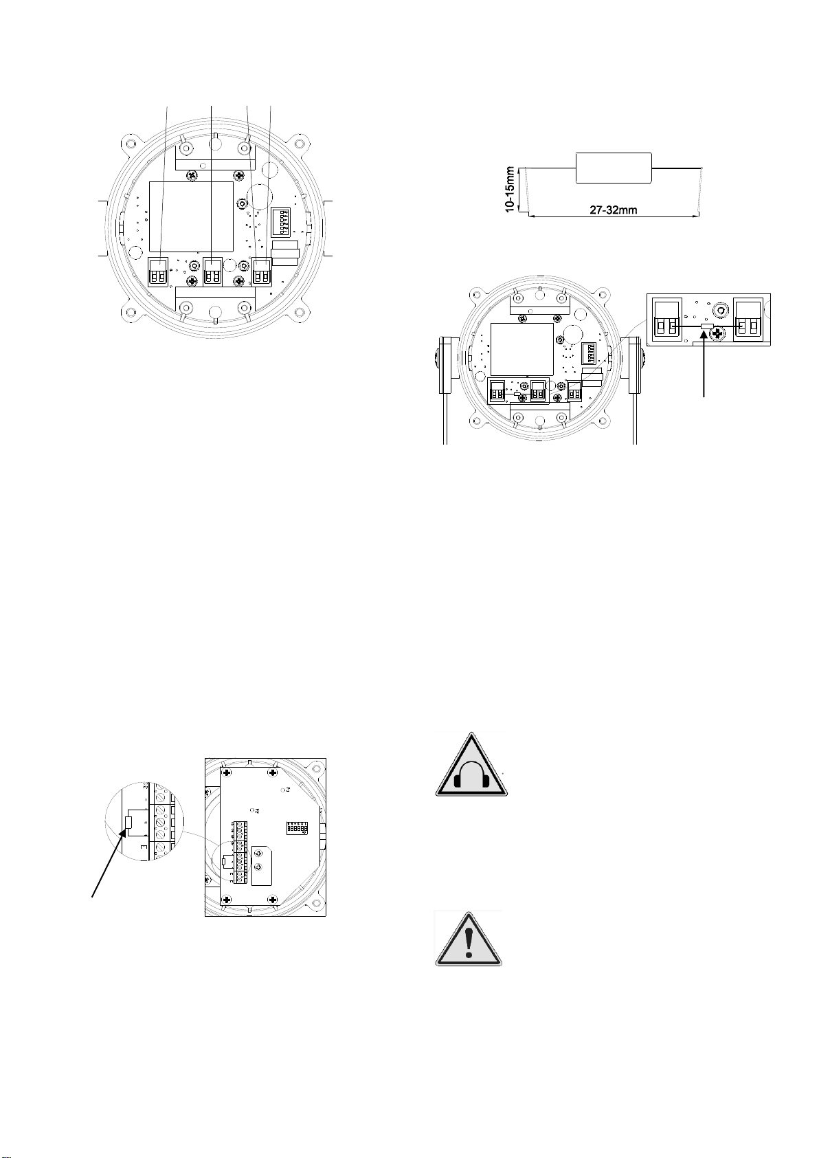
To maintain the ingress protection rating, the two off cable
entries must be fitted with suitably rated, certified cable entry
and/or blanking devices during installation.
2.6 Electrical Ratings
Part No.
Voltage
Beacon
Current
Sounder
Current
E2xC1LD2FDC024 /
E2xC1LD2RDC024
18-30Vdc
346mA
284mA
E2xC1LD2FDC048 /
E2xC1LD2RDC048
42-54Vdc
115mA
146mA
E2xC1LD2FAC115 /
E2xC1LD2RAC115
115-120Vac
50/60Hz
102.4mA
104mA
E2xC1LD2FAC230 /
E2xC1LD2RAC230
220-230Vac
50/60Hz
49.4mA
54mA
It is important that a suitable power supply is used to run the
equipment. The power supply selected must have the
necessary capacity to provide the input current to all the
units.
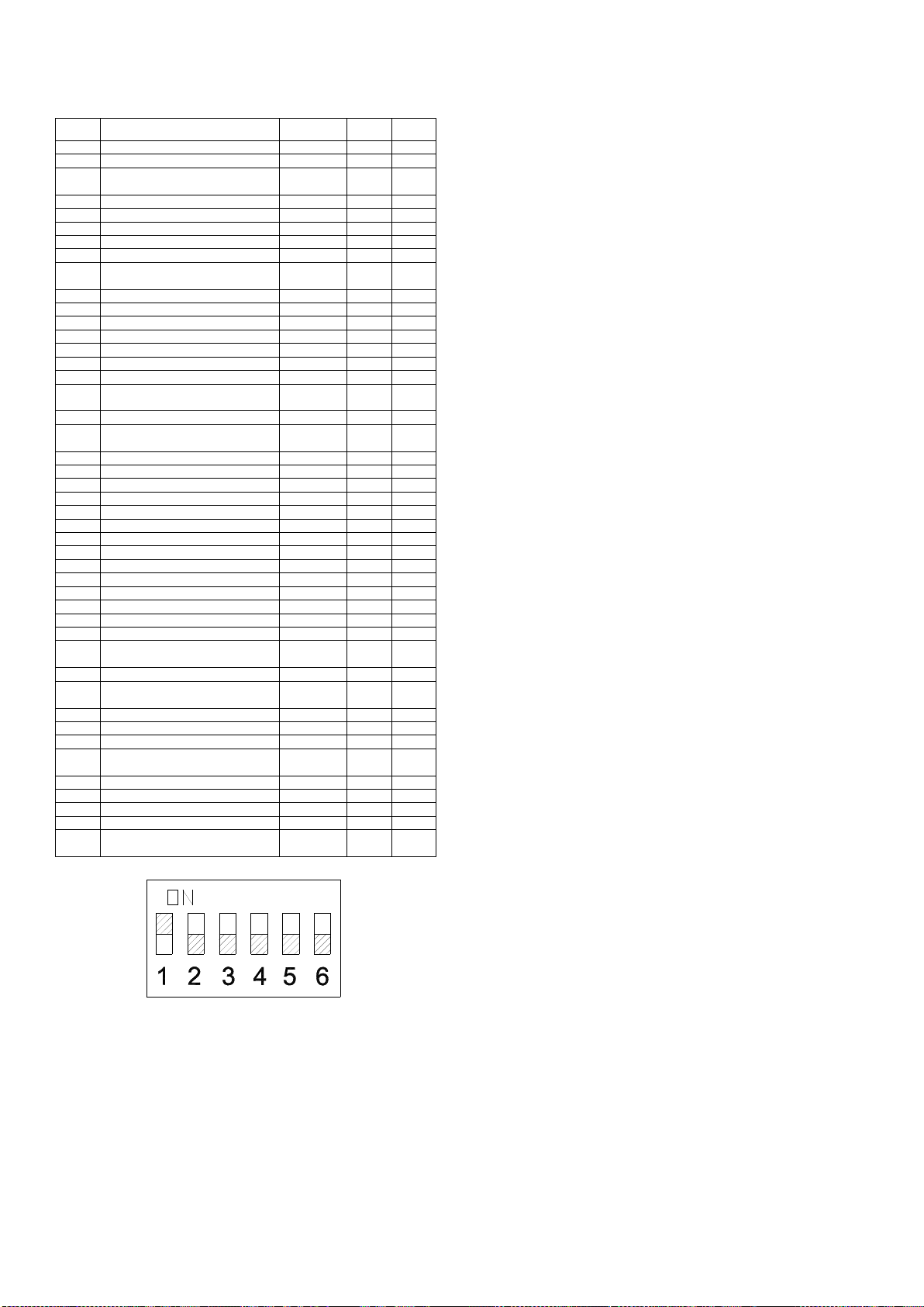
The input current will vary according to the voltage input level
and the frequency of the tone selected. The current levels
shown above are for the tone resulting in max. current draw
(tone 1 - 340Hz Continuous) and worst-case input voltage
producing max. current.
3) Special Conditions of Use
When used for a Group III application, the surface of the
enclosure may store electrostatic charge and become a
source of ignition in applications with a low relative humidity
<~30% relative humidity where the surface is relatively free of
surface contamination such as dirt, dust, or oil.
Guidance on protection against the risk of ignition due to
electrostatic discharge can be found in EN TR50404 and IEC
TR60079-32.
End user shall adhere to the manufacturer’s installation and
instruction when performing housekeeping to avoid the
potential for hazardous electrostatic charges during cleaning,
by using a damp cloth.
To maintain the ingress protection rating and mode of
protection, the cable entries must be fitted with suitably rated,
certified cable entry and/or blanking devices during
installation. If conduit is used for installation, seal conduit
within 18 inches from the enclosure.
Equipment with the flare horn shall not be installed with the
flare higher than horizontal (to avoid accumulation of dust).
The equipment incorporates metal parts isolated from earth,
having capacitance values exceeding the limits permitted in
the standards of certification. Mounting bracket –10.33pF;
Lens guard –12.33pF.
4) Location and Mounting
The location of the unit should be made with due regard to
the area over which the warning signal must be audible. They
should only be fixed to services that can carry the weight of
the unit.
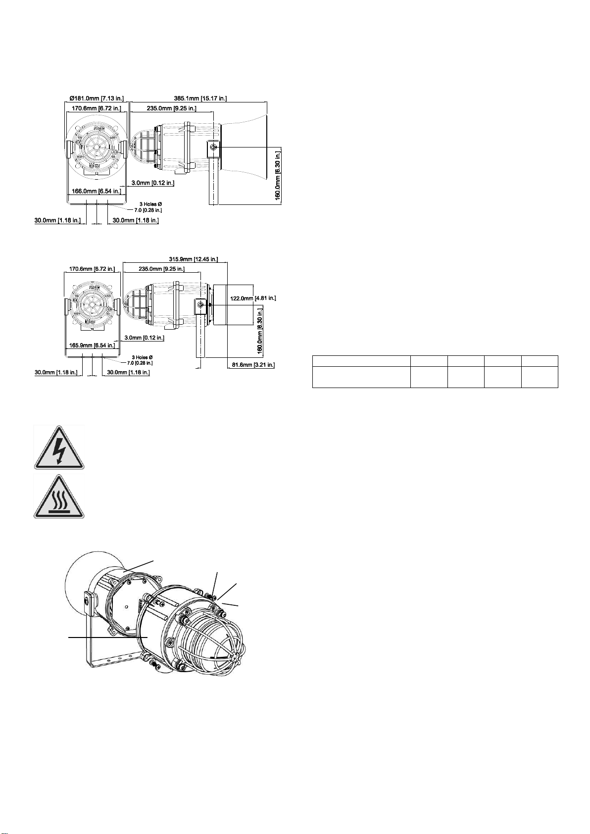
The E2x combined sounder beacon should be secured to any
flat surface using the three 7mm fixing holes on the stainless
steel U shaped mounting bracket. See Figure 1. The required
angle can be achieved by loosening the two large bracket
screws in the side of the unit, which allow adjustment of the
unit in steps of 18°. On completion of the installation the two

_______________________________________________________________________________________________________________________________
European Safety Systems Ltd. Impress House, Mansell Road, Acton, London W3 7QH sales@e-2-s.com Tel: +44 (0)208 743 8880
www.e-2-s.com Fax: +44 (0)208 740 4200
Document No. D209-00-511-IS-SC Issue C 13-06-17 Sheet 3 of 8
large bracket adjustment screws on the side of the unit must
be fully tightened to ensure that the unit cannot move in
service.
Fig. 1a Fixing Location for Combined Sounder Beacon Flare
Fig. 1b Fixing Location for Combined Sounder Beacon Radial
5) Access to the Enclosure
To access the enclosure, remove the four M4 posi pan head
screws, M4 spring and plain washers and withdraw the cover.
Fig. 2 Accessing the Enclosure.
To replace cover, check that the ‘O’ ring seal is in place.
Carefully push the cover in place. Insert and tighten down M4
screws, spring and plain washers in the order shown above
and tighten down.
6) Selection of Cable, Cable Glands, Blanking
Elements & Adapters
When selecting the cable size, consideration must be given
to the input current that each unit draws (see Table 1), the
number of sounders on the line and the length of the cable
runs. The cable size selected must have the necessary
capacity to provide the input current to all of the sounders
connected to the line.
The dual entries can be ordered with one of the following
options:
2-off M20 x 1.5 thread
2-off ½” NPT thread
1-off M20 x 1.5 & 1-off ½” NPT thread
To maintain the ingress protection rating and mode of
protection, the cable entries must be fitted with suitably rated,
certified cable entry and/or blanking devices during
installation. If conduit is used for installation, seal conduit
within 18 inches from the enclosure.
For ambient temperatures over +40ºC the cable entry
temperature may exceed +70ºC or the cable branching
temperature may exceed +80ºC. Therefore suitable heat
resisting cables and cable glands must be used as per table
below
Ambient Temp.
40ºC
45ºC
50ºC
55ºC
Min. Rating of cables
and cable glands
90ºC
95ºC
100ºC
105ºC
If a high IP (Ingress Protection) rating is required then a
suitable sealing washer must be fitted under the cable glands
or blanking plugs.
For use in explosive dust atmospheres, a minimum ingress
protection rating of IP6X must be maintained.
For use in explosive gas atmospheres, a minimum ingress
protection rating of IP54 must be maintained.
7) Cable Connections
The E2xC1LD2 combined sounder beacon has separate
printed circuit boards in the sounder and beacon sections.
The terminals for the sounder are on the printed circuit board
in the sounder section and the terminals for the beacon are
on the printed circuit board in the beacon section (see figures
4a, 4b, 6a and 6b). See section 5 of this manual for access to
the enclosure. See section 9 and 10 for AC and DC wiring
diagrams respectively. Electrical connections are to be made
into the terminal blocks on the PCBA located in the
enclosure. See section 5 of this manual for access to the
enclosure.
Wires having a cross sectional area between 0.5 mm² to
2.5mm² can be connected to each terminal way. If an input
and output wire is required the 2-off Live/Neutral or +/-
terminals can be used. If fitting 2-off wires to one terminal
way the sum of the 2-off wires must be a maximum cross
sectional area of 2.5mm². Strip wires to 8mm. Wires may also
be fitted using ferrules. Terminal screws on the sounder
PCBA need to be tightened down with a tightening torque of
0.45 Nm / 4 Lb-in. Terminal screws on the beacon PCBA
need to be tightened down with a tightening torque of 0.56
Nm / 5 Lb-in. When connecting wires to the terminals great
Warning –Hot surfaces. External surfaces
and internal components may be hot after
operation, take care when handling the
equipment.
Warning –High voltage may be present,
risk of electric shock. DO NOT open when
energised, disconnect power before
opening.
(Appropriate cable entry devices
to be customer supplied)
Beacon
Housing
M4 Cover
Screw
M4 Spring
Washer
M4 Plain
Washer
Sounder
Housing

_______________________________________________________________________________________________________________________________
European Safety Systems Ltd. Impress House, Mansell Road, Acton, London W3 7QH sales@e-2-s.com Tel: +44 (0)208 743 8880
www.e-2-s.com Fax: +44 (0)208 740 4200
Document No. D209-00-511-IS-SC Issue C 13-06-17 Sheet 4 of 8
(Customer supplied
switches)
(Customer supplied
switches)
care should be taken to dress the wires so that when the
cover is inserted into the chamber the wires do not exert
excess pressure on the terminal blocks. This is particularly
important when using cables with large cross sectional areas
such as 2.5mm².
8) Wiring the Combined Beacon & Sounder
for Simultaneous or Independent
Operation.
By default, the Beacon and Sounder PCBAs are pre-wired
together for simultaneous operation. The units will be
powered simultaneously if either the sounder or beacon
board is powered. Stage switching is only available on the
sounder boards. If the sounder and beacon boards are
required to operate independently, the wires connecting the
Beacon and Sounder PCBAs should be removed from both
sets of terminal blocks, refer to fig. 3b & 5b.
9) AC Wiring
A 6-way terminal block is provided on the AC Sounder for
power. There are 2-off Live, 2-off Neutral and 2-off Earth
terminals in total. A 3-way terminal is provided for stage
switching. There are 1-off stage 2, 1-off stage 3 and 1-off
common terminals in total. 3-off 2-way terminal blocks are
provided on the AC beacon for power. There are 2-off +ve, 2-
off -ve and 2-off Earth terminals in total.
12.1 Wiring Diagrams
Fig 3a. E2xC1LD2 AC Simplified Block Diagram for
Simultaneous Beacon & Sounder Operation
(Pre-wired Connections left in place)
Fig 3b. E2xC1LD2 AC Simplified Block Diagram for
Independent Beacon & Sounder Operation
(Pre-wired Connections removed)
12.2 Stage Switching
12.2.1 Units First Stage Tones
Stage one (S1) Operation
Simply connect the supply
voltage to the L and N
supply terminals, (see fig.
4).
12.2.2 AC Units Second & Third Stage Tone
Selection (Sounder Only)
To select the second and third stage tones on the E2xC1LD2
AC sounder.
Stage two (S2) Operation
Power L and N,
link the Common-C and
S2 terminal.
Dip switch alters stage 2
tone.
Stage three (S3) Operation
Power L and N,
link the Common-C and
S3 terminals.
Dip switch alters stage 3
tone.
Fig. 4a AC Sounder Terminals
DIP Switch
Volume Control
S3
S2
C
E
N
L

_______________________________________________________________________________________________________________________________
European Safety Systems Ltd. Impress House, Mansell Road, Acton, London W3 7QH sales@e-2-s.com Tel: +44 (0)208 743 8880
www.e-2-s.com Fax: +44 (0)208 740 4200
Document No. D209-00-511-IS-SC Issue C 13-06-17 Sheet 5 of 8
NN L L E E
(Customer supplied
switches)
(Customer supplied
switches)
Fig. 4b AC Beacon Terminals
10) DC Wiring
A 10-way terminal block is provided on the DC Sounder.
There are 2-off +ve, 2-off -ve, 2-off stage 2, 2-off stage 3 and
2-off Earth terminals in total. 3-off 2-way terminal block are
provided on the DC Beacon. There are 2-off +ve, 2-off –ve, 1-
off stage2 and 1-off stage 3 terminals in total.
10.1 Wiring Diagrams
Fig. 5a E2xC1LD2 DC Simplified Block Diagram for
Simultaneous Beacon & Sounder Operation
(Pre-wired Connections left in place)
Fig. 5b E2xC1LD2 DC Simplified Block Diagram for
Independent Beacon & Sounder Operation
(Pre-wired Connections removed)
10.2 Stage Switching
10.2.1 Units First Stage Tones
Stage one (S1) Operation
Simply connect the supply
voltage to the + and -
supply terminals, (see fig.
6).
10.2.2 DC Units Second & Third Stage Tone
Selection
Stage two (S2) Operation
Power +ve and –ve,
link a -ve supply line to the
S2 terminal.
Dip switch alters stage 2
tone.
Stage three (S3) Operation
Power +ve and –ve,
link a -ve supply line to the
S3 terminal.
Dip switch alters stage 3
tone.
Fig. 6 DC Sounder Terminals
48V DC
Volume
Control
DIP Switch
S3
S2
-
+
E
24V DC
Volume
Control

_______________________________________________________________________________________________________________________________
European Safety Systems Ltd. Impress House, Mansell Road, Acton, London W3 7QH sales@e-2-s.com Tel: +44 (0)208 743 8880
www.e-2-s.com Fax: +44 (0)208 740 4200
Document No. D209-00-511-IS-SC Issue C 13-06-17 Sheet 6 of 8
-- ++ S2 S3
Fig. 6 beacon DC Terminals
10.3 Line Monitoring
On E2xC1LD2 DC units, DC reverse line monitoring can be
used if required. All DC sounders and beacons have a
blocking diode fitted in their supply input lines. An end of line
monitoring resistor can be connected across the +ve and –ve
terminals. If an end of line resistor is used it must have the
following values:
24V DC units
Minimum resistance 3K9 Ohms Minimum Power 0.5W
Minimum resistance 1K Ohms Minimum Power 2.0W
48V DC units
Minimum resistance 15K Ohms Minimum Power 0.5W
Minimum resistance 3K9 Ohms Minimum Power 2.0W
10.3.1 Sounder Line Monitoring
The resistor must be connected directly across the +ve and
-ve terminals as shown in the following drawing. Whilst
keeping its leads as short as possible, a spacing of at least
1/16” (1.58mm) must be provided through air and over
surfaces between uninsulated live parts.
Fig. 8 End of Line Resistor Placement
10.3.2 Beacon Line Monitoring
(Independent Beacon and Sounder
Operation Only)
The resistor must be connected directly across the +ve and
-ve terminals as shown in the following drawing. Form the
resistor legs as shown in Fig. 9a, remove the +ve and –ve
terminal plugs and fit the resistor across the two terminal
plugs before refitting them to the PCBA as shown in Fig. 9b.
A spacing of at least 1/16” (1.58mm) must be provided
through air and over surfaces between uninsulated live parts.
Fig. 9a End of Line Resistor Forming
Fig. 9b End of Line Resistor Placement
11) Settings
11.1 Tone Selection
The sounders have 45 different tones that can be selected for
the first stage alarm. The sounders can then be switched to
sound second and third stage alarm tones. The tones are
selected by operation of a DIP switch on the PCB for both DC
and AC units. The tone table on page six shows the switch
positions for the 45 tones and which tones are available for
the second and third stages. To operate the sounder on
stage 1 simply connect the supply voltage to the normal
supply terminals (+ve and –ve for DC units, L and N for AC
units).
11.2 Volume Control
The output level of the E2x sounder can be set by adjusting
the volume control potentiometer (see Fig 4 for AC & Fig 6 for
DC). For maximum output, set the potentiometer fully
clockwise.
11.3 Beacon Flash Rate Settings
The E2xBL2 beacons can produce different flash patterns as
shown in Table 1. The flash patterns are selected by
operation of the flash setting DIP switch on the PCB, Fig 10.
Warning –high-intensity light source. Avoid
looking directly at the light source for
extended periods of time.
Warning - High noise levels above 85dB(A)
during operation. High levels of noise may
cause hearing loss, wear suitable ear
protection when equipment is in operation.
End of Line Resistor

_______________________________________________________________________________________________________________________________
European Safety Systems Ltd. Impress House, Mansell Road, Acton, London W3 7QH sales@e-2-s.com Tel: +44 (0)208 743 8880
www.e-2-s.com Fax: +44 (0)208 740 4200
Document No. D209-00-511-IS-SC Issue C 13-06-17 Sheet 7 of 8
Fig. 10 DIP Switch Location
Table 1: Switch Positions for Flash Patterns
Fig. 11 Dip Switch
1=ON; 0=OFF
Example shown: 100000 = Flashing 1Hz (Default setting)
12) Interchangeable & Spare Parts
The Beacon lens cover is interchangeable, contact E2S Ltd for a
replacement lens cover available in various colours.
To change the lens cover, unscrew the 4-off M5 Cap screws, spring
and flat washers using a 4mm Allen Key. Remove the wire guard and
replace the old cover with the new cover.
Fig. 10 Replacement of beacon lens cover
Fit the wire guard back onto the housing, over the new lens cover
aligning the fixing holes of the guard, lens cover and housing. Refit
the fixings to hold into place, the fixings MUST be fitted in the order
shown above.
13) Maintenance, Overhaul & Repair
Maintenance, repair and overhaul of the equipment should
only be carried out by suitably qualified personnel in
accordance with the current relevant standards:
EN60079-19
IEC60079-19
Explosive atmospheres - Equipment repair,
overhaul and reclamation
EN 60079-17
IEC60079-17
Explosive atmospheres - Electrical
installations inspection and maintenance
To avoid a possible ELECTROSTACTIC CHARGE the unit
must only be cleaned with a damp cloth.
Units must not be opened while an explosive atmosphere is
present.
If opening the unit during maintenance operations a clean
environment must be maintained and any dust layer removed
prior to opening the unit.
Switch
Setting
S1 Mode
S2 Mode
S3 Mode
(123456)
(DC & AC)
(DC Only)
(DC Only)
000000
Steady High
Power
Flashing 1Hz
Flashing Triple
Strike
000001
Steady Low
Power
Flashing 1Hz
Flashing Triple
Strike
100000
Flashing 1Hz
Flashing
Double Strike
Flashing Triple
Strike
101000
Flashing
1.5Hz
Flashing 2Hz
Flashing
Double Strike
010000
Flashing 2Hz
Flashing Triple
Strike
Flashing Triple
Strike
110000
Flashing
Double Strike
Steady High
Power
Flashing Triple
Strike
001000
Flashing
Triple Strike
Flashing 2Hz
Flashing
Double Strike
Warning –Hot surfaces. External surfaces
and internal components may be hot after
operation, take care when handling the
equipment.
M5 screw
M5 spring washer
M5 flat washer

_______________________________________________________________________________________________________________________________
European Safety Systems Ltd. Impress House, Mansell Road, Acton, London W3 7QH sales@e-2-s.com Tel: +44 (0)208 743 8880
www.e-2-s.com Fax: +44 (0)208 740 4200
Document No. D209-00-511-IS-SC Issue C 13-06-17 Sheet 8 of 8
14) Tone Table
45 Tone 34Tone 380 0 1 1 0 1
1KHz 1s on, 1s off Intermittent
- PFEER Gen. Alarm
Tone 5
Tone 21 1 0 1 0 1Motor Siren - slow rise to 2400Hz44 Tone 5Tone 20 1 0 1 0 1
1200Hz Continuous
43 Tone 5Tone 21 0 0 1 0 1
Motor Siren - slow rise to 800Hz42 Tone 5Tone 20 0 0 1 0 1
Motor Siren - slow rise to 1200Hz41
Tone 27Tone 311 1 1 0 0 1
544Hz (100mS)/440Hz (400mS)
- NF S 32-001
40
Tone 17Tone 230 1 1 0 0 1
800Hz 0.25 sec on, 1 sec off Intermittent
39 Tone 45
Tone 341 0 1 0 0 12000Hz Continuous38 Tone 45Tone 90 0 1 0 0 1
1000Hz Continuous - PFEER Toxic Gas
37
Tone 5Tone 351 1 0 0 0 1
500-1200Hz 3.75 sec /0.25 sec
Australian Evac.
36
Tone 5Tone 360 1 0 0 0 1
420Hz @ 0.625 Sec Australian Alert
35
Tone 45Tone 381 0 0 0 0 1
1000 & 2000Hz @ 0.5 sec
Aletrnating - Signapore
34
Tone 5
Tone 20 0 0 0 0 1
745Hz @ 1Hz Intermittent
33 Tone 15Tone 261 1 1 1 1 0Two tone chime32 Tone 5Tone 260 1 1 1 1 0
660/1200Hz @ 1Hz Sweeping
31 Tone 5Tone 21 0 1 1 1 0
300Hz Continuous
30 Tone 5Tone 70 0 1 1 1 0
800/1000Hz @ 7Hz Sweeping
29 Tone 5Tone 21 1 0 1 1 0440Hz Continuous28 Tone 5
Tone 260 1 0 1 1 0554Hz Continuous27 Tone 15
Tone 2
1 0 0 1 1 0Bell26 Tone 5Tone 290 0 0 1 1 0
2400/2900Hz @ 50Hz Sweeping
25 Tone 5Tone 291 1 1 0 1 0
800/1000Hz @ 50Hz Sweeping
24 Tone 5Tone 60 1 1 0 1 0
800Hz @ 2Hz Intermittent
23 Tone 5Tone 21 0 1 0 1 0
544Hz @ 0.875 sec Intermittent
22 Tone 5Tone 20 0 1 0 1 0
554Hz/440Hz @ 1Hz Alternating
21 Tone 5
Tone 21 1 0 0 1 0660Hz Continuous20
Tone 5Tone 20 1 0 0 1 0
1.4KHz - 1.6KHz 1s, 1.6KHz - 1.4
KHz 0.5s - NFC48-265
19
Tone 5Tone 21 0 0 0 1 0
660Hz 1.8 sec on, 1.8 sec off Intermittent
18
Tone 27Tone 20 0 0 0 1 0
544Hz (100mS)/440 Hz (400m/S)
- NF S 32-001
17
Tone 5Tone 181 1 1 1 0 0
660Hz 150mS on, 150mS off Intermittent
16 Tone 5
Tone 20 1 1 1 0 0800Hz Continuous15 Tone 5Tone 41 0 1 1 0 0
800Hz 0.25 sec on, 1 sec off Intermittent
14 Tone 5Tone 150 0 1 1 0 0
2400Hz @ 1Hz Intermittent
13 Tone 5Tone 41 1 0 1 0 0
800/1000Hz @ 0.875Hz Alternating
12 Tone 5Tone 20 1 0 1 0 0
1000Hz @ 1Hz Intermittent
11 Tone 5Tone 71 0 0 1 0 0
2400/2900Hz @ 2Hz Alternating
10
Tone 2Tone 150 0 0 1 0 0
1200/500Hz @ 1Hz - DIN
PFEER P.T.A.P.
9
Tone 5Tone 21 1 1 0 0 0
500/1200/500Hz @ 0.3Hz Sweeping
8Tone 5Tone 100 1 1 0 0 0
2400/2900Hz @ 1Hz Sweeping
7Tone 5Tone 71 0 1 0 0 0
2400/2900Hz @ 7Hz Sweeping
6Tone 20Tone 30 0 1 0 0 0
2400Hz Continuous
5Tone 5Tone 61 1 0 0 0 0
800/1000Hz @ 1Hz Sweeping
4
Tone 5
Tone 20 1 0 0 0 0
500/1200Hz @ 0.3Hz sec
Slow Whoop
3
Tone 5Tone 171 0 0 0 0 0
800/1000Hz @ 0.25 sec Alternating
2
1 2 3 4 5 6 Tone 5Tone 20 0 0 0 0 0
340Hz Continuous1
Stage 3Stage 2
Switch
Frequency DescriptionStage 1
Fig. 9 Dip Switch
1=ON; 0=OFF
Example shown: 100000 = Tone 2 (Default setting)

This manual suits for next models
9
Table of contents
Other E2S Marine Equipment manuals

E2S
E2S A105N APPELLO DC User manual

E2S
E2S BExTS110D User manual

E2S
E2S E2xS2FDC024 User manual

E2S
E2S BExCS110-05D User manual

E2S
E2S D1xS1 Series User manual

E2S
E2S AL121H Series User manual

E2S
E2S BExS110D-R User manual

E2S
E2S Minialert IS-mC1 User manual

E2S
E2S GNExS1 User manual

E2S
E2S DL105H AlertAlight User manual
Popular Marine Equipment manuals by other brands

Skipper
Skipper EML224N-SA Operation and installation manual

GUIDANCE MARINE
GUIDANCE MARINE CyScan Installer's guide

Furuno
Furuno FW-200 Operator's manual

Thrane&Thrane
Thrane&Thrane Sailor 100 Satellite TV user manual

Seastar Solutions
Seastar Solutions HA1230 installation instructions

FITCH
FITCH Green Fuel Catalyst FHD-70 installation manual