MOFLASH SIGNALLING IS-S-02 Manual

INSTALLATION &
TECHNICAL INFORMATION
PLEASE READ PRIOR TO INSTALLATION
Website: www.moash.com Email: technical@moash.co.uk
Moash Intrinsically Safe Sounder Range
S00608, Issue 7, 28/07/2020
AUDIBLE SIGNALLING DEVICES
1
APPROVALS AND CONFORMITIES

2
1.0 Introduction
The Moash Intrinsically Safe Sounder product (IS-S-02) is ATEX and IECEx
certied. The Sounder is approved to be installed in Groups I (Mining) and
Group II (above ground), Zones 0, 1 or 2 with gas groups IIA, IIB, IIC and
Zones 20, 21 and 22 for dust groups IIIC and carries a temperature classication
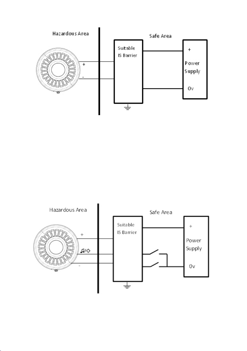
of T6. The Sounder comprises of a 2 stage alarm and has a total of 32 selectable
alarm tones via a DIP switch which is set upon installation. When powered via
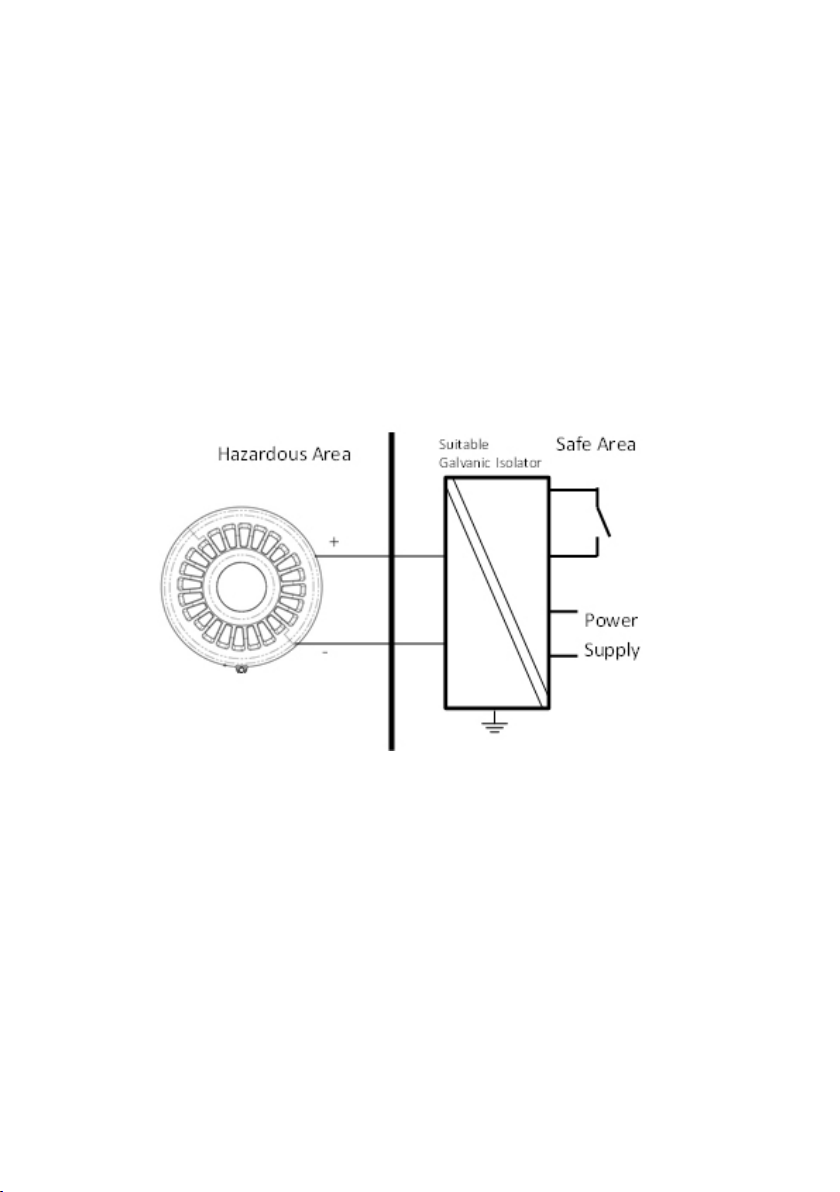
a suitable Galvanic Isolator or Zener Barrier the Sounder will draw a constant
33mA. The Sounder has diode reverse polarity protection and is also End of
Line resistor compatible.
2.0 Intrinsically Safe Labelling
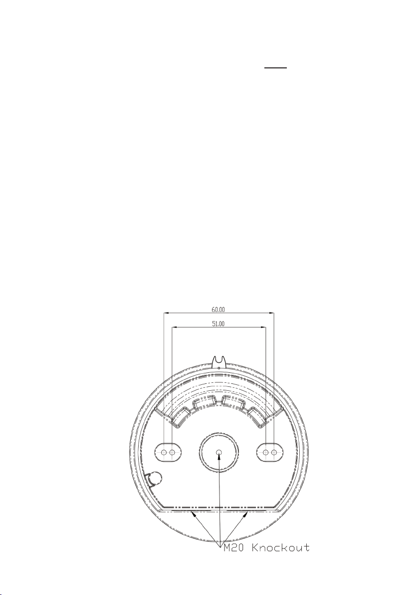
The product will have an individual serial number printed onto the head base
plate, an example of the sounder label is shown below.
These products have been tested by notied body Element Materials Technol-
ogy Rotterdam who are UKAS accredited to BS EN ISO/IEC 17025:2005 and
ISO/IEC 17065:2012. It is also a Notied Body for the ATEX Directive, an
IECEx Certication Body and an IECEx Testing Laboratory.
The sufx X at the end of the certicate numbers indicates that there are special
clauses added for safe use of these units.
3.0 Types of Approval and Standards Applied
The Moash IS Sounder product has been approved to the following standards:
IEC 60079-0:2011 / EN 60079-0:2012 + A11:2013
IEC 60079-11:2011 / EN 60079-11:2012
EN 54-3:2001+A1:2002+A2:2006

3
4.0 Zones, Gas Groups and Temperature Classications
The Moash Intrinsically Safe Sounder is certied to the following:
Ex ia IIC T6 Ga, Ex ia IIIC T85C Da, Ex ia I Ma.
This means that the units can be installed in locations with the following condi-
tions when connected to an approved system:
Zones
Zone 0 Explosive gas air mixture continuously present.
Zone 1 Explosive gas air mixture likely to occur in normal operation.
Zone 2 Explosive gas air mixture not likely to occur, and if it does, it will
only exist for a short time.
Zone 20 Explosive dust air mixture is continuously present.
Zone 21 Explosive dust air mixture likely to occur in normal operation.
Zone 22 Explosive dust air mixture not likely to occur, and if it does, it
will only exist for a short time.
Gas Groupings
IIA Propane Group, IIB Ethylene Group and IIC Hydrogen and Acetylene
M1 Methane, Carbon Dust
Equipment Category
1GD & M1 Temperature Range: -40°C < Ta <55°C
Dust
IIIA Fibres and Flying, IIIB Flour and Grain, IIIC Coal Dust and Metal Dust.
The maximum surface temperature of operating product in the Sounder will not
exceed 85°C.
A Declaration of Conformity and also the Sounder Range ATEX and IECEX
Certicates are available on request or alternately visit www.Moash.co.uk.

4
5.0 Installation
The TimeSaver base enables quick and easy installation of these units with no
extra cabling to be made to the head of the unit. Connections are made to the
base during the initial wiring phase which results in faster and more reliable in-
stallation. The sounder head ‘twists and clicks’ into the base on commissioning
thus avoiding any wiring and connection problems associated with traditional
installations.
If required, the mechanism for locking the sounder to the base can be activated
by removing the thin section of plastic shown in Fig. 1 with side cutters or a
similar tool. To open a locked head, remove the small rubber bung from the hole
on the side of the sounder, insert a tool into the hole and depress the clip whilst
twisting the head.
An alternative locking method is shown in Fig. 1b. Drive the hexagonal locking
screw forward by turning a 1.5mm hexagonal key clockwise until the head is
locked.
The O-ring and bung must be re-tted to maintain the weatherproong.
General Requirement
The Sounder must be installed in accordance with the latest EN60079-0
specication or equivalent IEC specication. With consideration for any local
installation requirements and should only be carried out by appropriately com-
petent and qualied personnel.
Fig.1b

• The location of the Sounder should be chosen with due regard to the area
over which the signalling device must be audible.
• These units are suitable for wall or ceiling mount only.
• Environmental exposure conditions during installation should be dry. Moist
or wet conditions should be avoided.
• Avoid mounting the Sounder where it may be subjected to excessive vibration.
To mount the unit
• Remove the head from the base by rotating anticlockwise until it comes
free.
• Remove the appropriate xing hole and conduit knockouts from the back
box.
• The back box provides IP66* protection. For this to be maintained, suitably
rated (minimum IP66) M20 cable glands must also be used for cable entry/
exit.
• Insert cable glands and attach to surface.
• Select required wiring option for required operation (see wiring section).
• Select tone by conguring the DIP switches in the head unit, the tone table
can be found on page 12 of this booklet (Pre-set to tone 18).
• Relocate head onto mounted base unit & rotate clockwise until locked in
place.
5

6.0 Wiring
Table above indicates markings inside the base of the unit for wiring connec-
tions. Each unit must be powered via an approved Zener Barrier or Galvanic
Isolator with entity perameters that do no exceed:
Uo:28v, Io: 93mA, Po:660mW, Ci:0, Li:0
Operation of the Sounder Range can be taken from the table below:
Single Stage Alarm
Before nal installation of the IS-S-02 Sounder head unit onto the installed base
the alarm tone must be set (see page 5).
To control the Sounder use either a switch in the safe area on either the positive
or negative lines into the Barrier, or by turning the power supply on and off ,this
is shown at the top of page 7.
6
Line Terminal Marking
Common Positive Supply IN (3) IN+
Sounder Negative Supply (2) -
Beacon Negative Supply (1) ♫/☼
Line Terminal Marking Sounder
Active
Second
Stage
Common Positive
Supply IN (Uo)
(3) IN+ + +
Sounder
Negative Supply
(2) - - -
Beacon/2nd Stage
Negative Supply
(1) ♫/☼ -

7
Two Stage Alarm
When a two stage alarm is required it is possible to activate an alternate tone
by connecting the “♫/☼” (Beacon ground) pin to 0v (as detailed in the table on
page 5).
For this application, a barrier with 2 Diode return paths is required as shown in
the diagram below:
Switching between return paths for the 2 stage system will enable the 2nd tone.
Second stage tone can be found in the table on page 12.

8
Galvanic Isolator
The IS-S-02 Intrinsically Safe Sounder Range is compatible for use with suit-
ably rated Galvanic Isolators. The Glavanic Isolators have the advantage of not
requiring an Isolated high integrity earth to be installed to connect the Zener
Barriers. These Isolators are often more expensive per unit but may reduce
installation costs as the earth is not required.
The IS-S-02 range can be powered by the Galvanic Isolators with matching pa-
rameters as described in the entity parameters section of the installation sheet.
The Sounder can be turned on and off either by using a suitably placed switch
in the positive or negative rails (switch must be of suitable ratings if installed in
the Hazardous area), or by turning the Galvanic Isolator on and off.
As with the Zener barriers, the second stage alarm can be triggered when using
Galvanic Isolators, however an additional Intrinsically Safe relay is required to
make the additional connection.
As with all equipment in the system, the correct ratings must be maintained to
keep the integrity and safety to the correct levels. The relay can be switched to
change between stage 1 and stage 2.

9
End of line monitoring is applicable to the Sounder Product. For this to func-
tion correctly the resistor must be connected between the IN+ terminal and the
Sounder Negative Supply. A suitable Zener Barrier which can allow reverse
polarity monitoring to take place and a re panel compatible with Intrinsically
Safe products must also be used.
If required, an external switch can be wired in series with the (1) and/or (2)
connections to give independent remote change over from 1st stage to 2nd stage
tones. This switch must conform to Intrinsically Safe installation (EN 60079-
0:2012 + A11:2013, EN 60079-11:2012, EN 50303:2000).

10
7.0 Maintenance
Little or no maintenance is required during the normal working life of the
product. The Moash Intrinsically Safe enclosures are resistant to most acids,
alkalis and chemicals and have been designed to withstand severe weather
conditions. However it is suggested that continuous supervision and periodic
inspections may be required in relation to the requirements of the installation as
per IEC 60079-17.
To avoid the possibility of a potential electrostatic charge build up, it is
recommended that the exterior of the product is periodically wiped down with
a clean damp cloth. At this point a visual inspection is recommended to ensure
that the product is in good working order and no damage has been sustained
during its normal operation.
The enclosure is non-conducting and may generate an ignition-capable level of
electrostatic charge under certain extreme conditions. It is the responsibility of
the user to ensure that the equipment is installed in a location where it will not
be subjected to external conditions that might cause a build-up of electrostatic
charge on the surface of the unit,
8.0 Conditions for Use
The Moash Intrinsically Safe Signalling Range uses an enclosure rated at
IP66*. To ensure that this rating is maintained once installed, a suitable cable
gland must be used which matches this level of protection. The base of the unit
contains 3x M20 knockouts for wiring in purposes, and only those required
should be used. Any that are removed must have at least an IP66 rated gland
tted with cable passing through it or suitable plug.
*= meets the IP33C requirements of EN 54-3:2001+A1:2002+A2:2006.

11
As previously stated in the installations sheet, the Intrinsically Safe Sounder
Range must be powered via a suitable Zener Barrier or Galvanic Isolator whose
characteristics do not exceed:
Uo:28v, Io: 93mA, Po:660mW
The value for Uo must be between 16v and 28v, and Io should not be below
50mA.
This range of products is only to be powered via a correctly rated Zener Barrier
or Galvanic Isolator. To power these units up without the correctly rated barrier
could damage these products and so void any protection ratings.
Specic Conditions of Use:
1. Clean equipment regularly to prevent dust build-up with a damp or anti-
static cloth only.
2. Equipment only suitable for xed installation.
3. It must be ensured that the equipment is installed in accordance with
IEC 60079-14 and IEC 60079-25 and that capacitance and inductance limits
are not exceeded by distributed capacitance (Cc) or distributed inductance
(Ic) due to cable length.
Table of Entity Parameters
Parameter Barrier Supply
Ui 28V
li 93 mA
Pi 660 mW
Li 0
Ci 0

12
9.0 Tone Table
TONE TONE TYPE TONE DESCRIPTION/ APPLICATION DIP SWITCH
1-2-3-4-5-62nd Stage dB(A) @ 1m
1. 970Hz O-O-O-O-O-O 18 87
2. 800Hz/970Hz @ 2Hz O-O-O-O-I-O 1 91
3. 800Hz – 970Hz @ 1Hz O-O-O-I-O-O 1 91
4. 970Hz 1s OFF/1s ON O-O-O-I-I-O 1 92
5. 970Hz, 0.5s/ 630Hz, 0.5s O-O-I-O-O-O 4 92
6. 554Hz, 0.1s/ 440Hz, 0.4s (AFNOR NF S 32 001 ) O-O-I-O-I-O 1 89
7. 500 – 1200Hz, 3.5s/ 0.5s OFF (NEN 2575:2000 Dutch Slow Whoop) O-O-I-I-O-O 1 90
8. 420Hz 0.6s ON/0.6s OFF (Australia AS1670 Alert tone) O-O-I-I-I-O 9 93
9. 1000 - 2500Hz, 0.5s/ 0.5s OFF x 3/1.5s OFF ( AS1670 Evacuation) O-I-O-O-O-O 1 97
10. 550Hz/440Hz @ 0.5Hz O-I-O-O-I-O 19 94
11. 970Hz, 0.5s ON/0.5s OFF x 3/ 1.5s OFF (ISO 8201 ) O-I-O-I-O-O 1 92
12. 2850Hz, 0.5s ON/0.5s OFF x 3/1.5s OFF (ISO 8201) O-I-O-I-I-O 1 90
13. 1200Hz – 500Hz @ 1Hz (DIN 33 404) O-I-I-O-O-O 1 89
14. 400Hz O-I-I-O-I-O 18 92
15. 550Hz, 0.7s/1000Hz, 0.33s O-I-I-I-O-O 1 93
16. 1500Hz – 2700Hz @ 3Hz O-I-I-I-I-O 1 98
17. 750Hz I-O-O-O-O-O 1 93
18. 2400Hz I-O-O-O-I-O 1 105
19. 660Hz I-O-O-I-O-O 18 93
20. 660Hz 1.8s ON/1.8s OFF I-O-O-I-I-O 19 93
21. 660Hz 0.15s ON/0.15s OFF I-O-I-O-O-O 19 93
22. 510Hz, 0.25s/ 610Hz, 0.25s I-O-I-O-I-O 1 92
23. 800/1000Hz 0.5s each (1Hz) I-O-I-I-O-O 1 95
24. 250Hz – 1200Hz @ 12Hz I-O-I-I-I-O 1 91
25. 500Hz – 1200Hz @ 0.33Hz I-I-O-O-O-O 1 95
26. 2400Hz – 2900Hz @ 9Hz I-I-O-O-I-O 18 90
27. 2400Hz – 2900Hz @ 3Hz I-I-O-I-O-O 18 90
28. 500 - 1200Hz, 0.5s/ 0.5s OFF x 3/1.5s OFF ( AS1670 Evacuation) I-I-O-I-I-O 8 93
29. 800Hz – 970Hz @ 9Hz I-I-I-O-O-O 1 95
30. 800Hz – 970Hz @ 3Hz I-I-I-O-I-O 1 95
31. 800Hz, 0.25s ON/1s OFF I-I-I-I-O-O 1 92
32. 500Hz – 1200Hz, 3.75s/0.25s OFF (AS2220) I-I-I-I-I-O 8 96
Note:EN54-3 Compatible Tones are 1,2,3,6,7 & 13
All dB readings have been taken with Intrinsically safe barrier in place, dB readings are ±3dB(A).
For EN54-3 Sound Pressure Level Data see Document MOIS02
Table of contents
Other MOFLASH SIGNALLING Marine Equipment manuals

MOFLASH SIGNALLING
MOFLASH SIGNALLING SB150-1 Series Manual

MOFLASH SIGNALLING
MOFLASH SIGNALLING SB150-1 Series Manual

MOFLASH SIGNALLING
MOFLASH SIGNALLING SB150-1 Series Manual

MOFLASH SIGNALLING
MOFLASH SIGNALLING AE40M-24R-SB User manual

MOFLASH SIGNALLING
MOFLASH SIGNALLING SD125 Series Manual

MOFLASH SIGNALLING
MOFLASH SIGNALLING SB150-1 Series User manual

MOFLASH SIGNALLING
MOFLASH SIGNALLING S00608 Manual

MOFLASH SIGNALLING
MOFLASH SIGNALLING AE100M Series Manual