NKE PROCESSOR HR User manual

Zi de Kerandré – Rue Gutenberg – 56700 – HENNEBONT
http://www.nke-marine-electronics.com .
n° Audiotel 0 892 680 656 - 0,34€/min
PROCESSOR HR
Part number: 90-60-373
USER MANUAL
AND INSTALLATION GUIDE
Version V3.7

2 HR_PROCESSOR_um_EN_37
Contents
1. INTRODUCTION 4
2. THE TOPLINE NETWORK WITH PROCESSOR HR 4
3. PROCESSOR HR 4
4. SYSTEM DESCRIPTION (IMOCA TYPE) 6
5. INSTALLATION OF THE PROCESSOR HR 7
5.1 INSTALLATION OF A BRAND NEW NKE SYSTEM 7
5.2 INSTALLATION OF THE PROCESSOR REGATTA WITH AN EXISTING NKE SYSTEM 7
5.3 ADDING THE PROCESSOR HR TO YOUR NKE SYSTEM 9
5.4 ETHERNET CONFIGURATION 11
5.5 CONNECTING THE PROCESSOR HR 12
5.6 CONNECTION TO THE TOPLINE BUS 13
5.7 CONNECTOR 3D HULL AND 3D MAST 13
5.8 NMEA1/NMEA2 CONNECTORS 13
5.9 NMEA INPUT 14
5.10 NMEA SENTENCES INPUT PRIORITY RULES 16
5.11 NMEA OUTPUT 17
5.12 OPTION CONNECTOR 18
NO CABLE IS SUPPLIED BY DEFAULT. THE CONNECTOR IS A BINDER 4 CONTACTS SERIES 620
(IP67/SNAP-IN/DEXT=11.5MM). THE PIN ASSIGNMENT IS AS FOLLOWS: 18
6. CONFIGURATION OF THE PROCESSOR HR 19
6.1 ACTION OF THE LINKS 19
6.1.1 Actions 19
6.1.2 Installation and calibrations 19
6.1.3 Parameters directly settable from the Multigraphic 25
6.1.4 Analyse 26
6.1.5 Tools 27
6.1.6 Datalogs 28
6.1.7 Support 28
6.2 SOFTWARE UPDATE 29
6.3 CONFIGURE THE FILE VARIABLE.CSV 29
6.4 CHOOSING THE LANGUAGE 30
6.4.1 Patch installation procedure 30
7. ALGORITHM FOR THE PROCESSED FUNCTIONS 31
7.1 FUNCTIONS FOR BOAT MOTION 31
7.2 FUNCTIONS FOR BOAT SPEED 32
7.3 FUNCTION FOR WIND DATA 33
8. THE PILOT HR 34
8.1 ACTIVATION 34
8.2 SELECTING THE HR AUTOPILOT ON THE MULTIGRAPHIC 34
8.3 SELECTION OF PILOT HR WITH THE GYROGRAPHIC 35
9. CALIBRATING YOUR SYSTEM 36
9.1 INTRODUCTION 36

3 HR_PROCESSOR_um_EN_37
9.2 CALIBRATION ORDER 36
9.3 CALIBRATING THE COMPASS 37
9.4 ROLL AND PITCH CALIBRATION 37
9.5 CALIBRATING BOAT SPEED 37
9.5.1 Linear boat speed response against boat’s heel angle 38
9.6 CALIBRATING FOR DRIFT 39
9.6.1 Using a drift calibration adjustment value: 40
9.7 CALIBRATING TRUE WIND SPEED 40
9.8 APPARENT WIND ANGLE 42
9.9 CALIBRATING TRUE WIND ANGLE 43
10. PERFORMANCE AND POLAR TABLES 46
10.1 READING A POLAR TABLE 47
10.2 READING A POLAR DIAGRAM 48
10.3 PERFORMANCE FUNCTIONS 49
11. ADDENDUM A 52
11.1 CONFIGURING THE PC FOR THE FIRST CONNECTION TO THE PROCESSOR HR 52
11.1.1 Connecting the Processor HR to the PC 52
11.1.2 Configuring the network connection with Windows XP 52
11.1.3 Configuring the network connection with Windows Seven 53
11.1.4 Testing the connection with the Processor HR 57
12. FREQUENTLY ASKED QUESTIONS 58

4 HR_PROCESSOR_um_EN_37
1. INTRODUCTION
Thank you for choosing nke and the PROCESSOR HR. You have purchased a processor
that sits at the heart of a system which provides the autopilot, the navigation programme,
the tactician, the crew and of course the skipper all the data they require. The data
provided is optimised for accuracy, responsiveness and performance.
In this manual you will find all the information necessary to:
- Carry out Installation, configuration and calibration of the Processor HR and sensors
- Access all the functions offered by the Processor HR
- Get the best performance from your boat.
2. THE TOPLINE NETWORK WITH PROCESSOR HR
The Topline system consists of sensors and displays networked with a single 3 wire cable
(shield: 0V, white: +12V, black: Data). Data is carried on the black “DATA” wire.
Displays have a variable address ranging from 1 to 20 while the sensors have a fixed
address with a value comprised between 21 and 210. The network is managed from one
of the displays that will be chosen as “MASTER” during the system commissioning. Its
address will be “1”.
Once turned on, the “MASTER” will scan all the addresses to discover all the displays and
sensors which are connected to the network.
Once the “MASTER” has scanned the network, it will ping only the channels it has
identified. Also, the “MASTER” will randomly ping the channel “0” (non identified display).
A specific answer from a display will generate an address for that display to integrate
dynamically with the network.
3. PROCESSOR HR
The Processor HR provides the following:
1. Performance:
Accurate measurement of wind speed and angle (true and apparent), boat speed,
speed over ground, the boat movements, all with sensitivity to small changes.
Accurate measurement of acceleration and the boat’s attitude (magnetic heading,
angles, acceleration, turn rates, magnetometric vector)
Accurate dynamic calculation of true wind as a result of the compensation of
measured data from the masthead sensor, the geometry between the mast and the
hull and the use of corrections table.

5 HR_PROCESSOR_um_EN_37
2. Fast data provision:
High speed data flow (fast reactivity to the measurements from sensors providing
high speed updates to the autopilot and data display).
Fast data rate interface with the on-board PCs for the major navigation packages
(via the SailNet protocol on IP and various gateways). Compatible with the Proteus
communication system.
3. Safe and secure operation:
Integrated safety: various safe modes allow use of the main functions without the
Processor Regatta.
The use of the lightest possible Linux OS ensures real time operation without
background task (or virus) and avoiding mechanical moving parts (such as hard
disk, fans…)
Auto diagnostic log for a good understanding in case of malfunction.
4. Standardisation :
Simple and open formats and protocols specified for:
Variables logs
Variable exchange protocol via fast RS232/NMEA0183 or IP.
Adjustment for the linear calibrations, filtering, alarms and non-linear calibration
files, polar tables.
Use of one single variable definition base for each level: in the remote Gyropilot
Graphic display, the Processor HR, the variables log, the compatible navigation
software (Deckman), the IP broadcast, the post-processing software (Excel..), the
diagnostic software (Toplink ...).
5. Post-processing:
Internal communication for diagnostics and modelling.
6. Open data:
Functions can be customized or translated (display on the Gyropilot Graphic,
Deckman, Tools).
Open IP protocol for « SailNet » variables exchange (Linux/windows libraries with
samples supplied, possibility to use several boats and/or navigation programs
simultaneously).
7. Upgrades:
Easy Processor HR update via IP
Use of the Topline peripherals with a Flash memory for onboard update with PC
Toplink.
Processor HR interface page on the Gyropilot Graphic display for easy HCI update.
8. Power management:
Allows the on board PC to operate in standby mode while getting the performance
data on the nke displays.
The Processor HR enhances the wind data (faster refresh and less noise). As a
consequence, the autopilot steering is optimized and reduces the use of the ram’s
motor.

6 HR_PROCESSOR_um_EN_37
4. SYSTEM DESCRIPTION (IMOCA TYPE)
The equipment featured in this drawing is for indication only.
It does not reflect your own system.
7 HR_PROCESSOR_um_EN_37
5. INSTALLATION OF THE PROCESSOR HR
In this chapter we will cover the installation of the unit and all calibration required in the
Topline network environment.
5.1 Installation of a brand new nke system
All units except the Processor Regatta must be installed first. Please refer to the manual
for each unit (sensors, displays…). We recommend using the Mutltigraphic or
Gyrographic as the system’s Master.
Once the system is installed, refer to “How to integrate Processor Regatta in an existing
nke system” to complete the installation.
5.2 Installation of the Processor Regatta with an existing nke system
As a first step, you need to update every component connected to the Topline network.
This is done with the « Toplink2 » software, or alternatively you can send the units to nke
customer support.
Firmware, database and the Toplink2 software (requires the Topline USB interface 90-60-
482) are all available for download at the following address: http://www.nke-marine-
electronics.com in the technical area (requires a password – access to trade only).
WARNING
- Please take time to read this manual carefully before you start installation.
- Any connection to the TOPLINE bus must be performed through the specific interface
box: 90-60-417.
- Any work on the TOPLINE bus requires the system to be powered off.
8 HR_PROCESSOR_um_EN_37
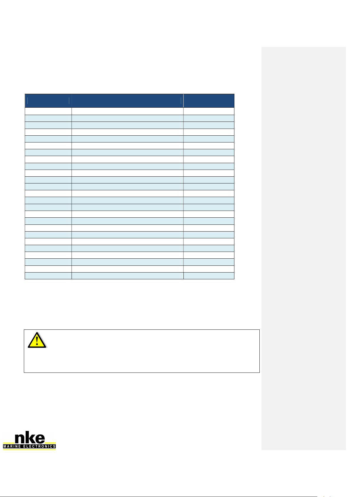
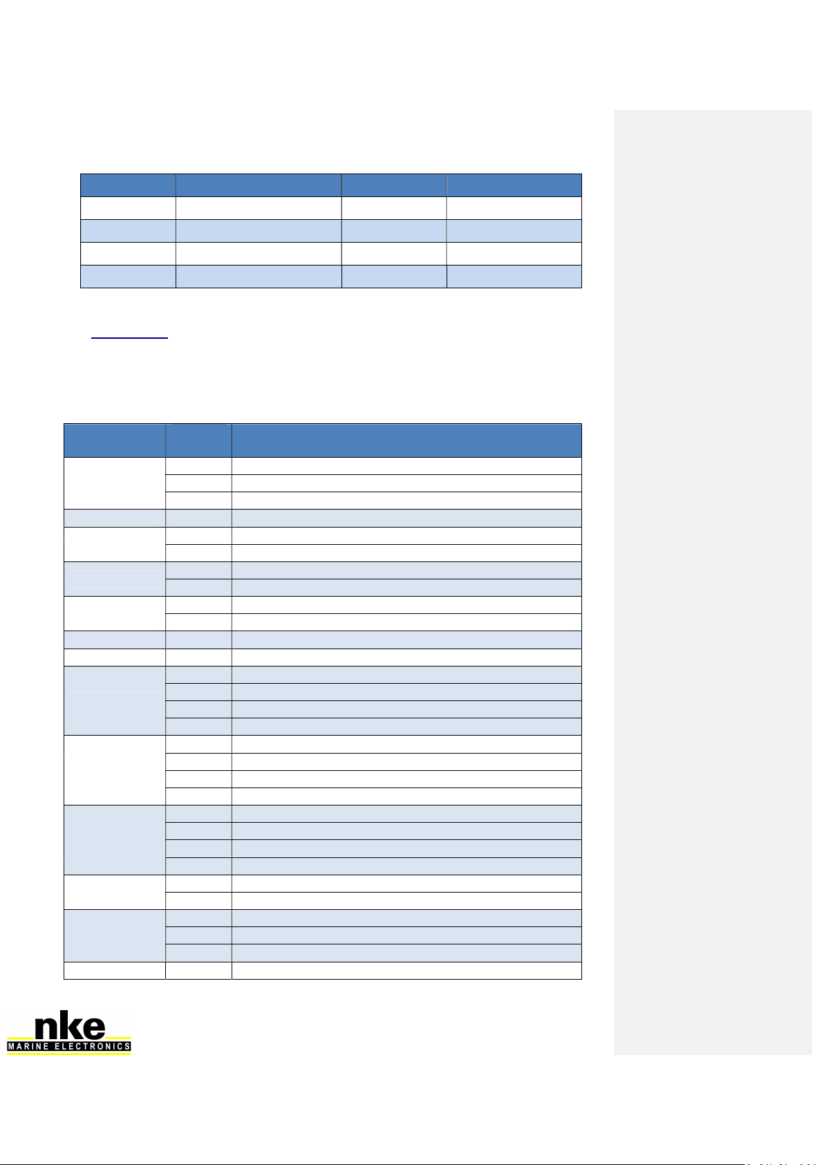
Table of versions compatibility with the Processor HR:
Module type Description Minimum Version
required
Display Performance Limited use
Display Multigraphic All versions
Display Gyropilot Graphic V3.1
Display SL50 V1.4
Display TL25 V1.5
Interface Remote control (wired) V2.1
Interface Radio receiver V2.4
Interface NMEA output interface
Interface NMEA input interface V1.2
Interface Toplink 2 N.A.
Interface WiFi box All versions
Sensor Single battery pack control Not compatible
Sensor Dual battery pack control Not compatible
Sensor Battery Monitor 500 All versions
Sensor 3D Sensor N.A.
Sensor Mast angle sensor V1.4
Sensor HR 100 barometric sensor V1.0
Sensor Ultrasonic starboard / port V1.6
Interface Speed and depth Interface V2.0
Interface Dual-speed and depth Interface V2.0
Sensor Carbowind HR V1.8
Sensor AG HR V1.8
Sensor Regatta Compass Interface V1.4
Sensor Fluxgate compass V1.7
Autopilot Pilot processor V2.8
Once you have ensured that all units are up to date with a compatible version, you can
power the system on and check that it works properly. We strongly recommend choosing a
Multigraphic or Gyropilot Graphic display as Master of the Topline network. This will
make the integration of the Processor Regatta easier to manage.
WARNING
If the instruments connected to the bus are not up to date with the latest firmware version,
the PROCESSOR HR cannot work and an error message is displayed in the "Main
Events" log to indicate the out of date instrument.
9 HR_PROCESSOR_um_EN_37
+
+
5.3 Adding the Processor HR to your nke system
When all the sensors, displays and interface units have been upgradedcompatible with the
Processor HR and fully working, you are ready to add the Processor HR to the network.
Once in place, it will become the Master. Therefore, the existing Master has to be deleted
so that the Topline network is clean of any Master.
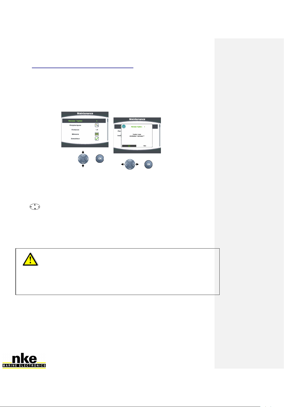
- If the Multigraphic (current Master) must be given a new node:
- If the Gyropilot Graphic (current Master) must be given a new node:
Display the Main Menu (Menu: main) with the Page key of the Gyropilot
Graphic
Choose Configuration and then Initialisation adress with the navigation pad
11
Accept with Ent,
You will get the following message « To set the address to 0 press Ent»,
accept again by pressing Ent,
the following message will display «Gyropilot address 0»
The 3D sensor must be connected to the « 3D HULL » connector before connecting the
PROCESSOR HR (refer to the unit’s manual). The PROCESSOR HR will automatically
detect those sensors (version 2.4 and up).
When powering the Topline network on, a blue LED situated on the front face of the
PROCESSOR HR indicates the working status. The PROCESSOR HR always acts as the
Master. When the system is powered on, the Master will create 2 « Lists ». Allow 30
seconds for boot completion.
WARNING
10 HR_PROCESSOR_um_EN_37
+
+
LED status Working status or fault description
LED off - Processor is powered off or faulty.
Blue Led
1 blip every 3
seconds
▲ 3s ▲
- Processor HR in normal working status
- internal auto-check is correct
100ms blip rate
▲ ▲ ▲ ▲ ▲ ▲ ▲
- Processor HR is booting
1 blip per second
▲ ▲ ▲ ▲
-
The Processor has detected a serious error (lost a sensor,
firmware version is not compatible...
Fixed light - Processor is out of work or booting.
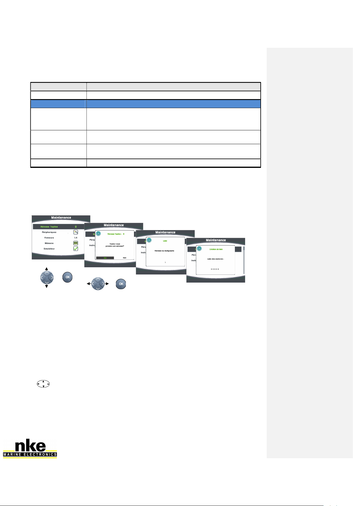
Once the PROCESSOR HR has started (Blue LED blips every 3 seconds), you can give a
new node number to the Gyropilot Graphic which has been used previously to check the
system. Use the following procedure:
For the Multigraphic:
Gyropilot Graphic:
the message « set an address in the Gyropilot in Menu/Configuration » is
displayed on the Gyropilot Graphic. It has not been initialized.
The system boot must be fully completed before any node can request an
address to the Processor. Once the data is displayed on the TL25, allow another 10
seconds.
Display the Main Menu (Menu principal) with the Page key of the Gyropilot
Graphic
Choose Configuration and then Initialisation adresse with the navigation pad
11
Accept with Ent,
The following message is displayed « to get an address press ENT», press
Ent,

11 HR_PROCESSOR_um_EN_37
The following message is displayed « liste» and the Gyropilot gets a node
number which will be temporarily displayed.
Press Page to exit.
The List creation is a long process (30 seconds). Always wait until the PROCESSOR HR
boot is completed (blue LED = 1 blip every 3 seconds) before asking for a new node
number.
5.4 Ethernet configuration
Depending on the network configuration on board your boat, several connection options
are possible between your Processor HR and the PC.
Direct Ethernet connection:
The network cable is supplied with the Processor HR. It is a crossover cable that allows
direct connection to your PC.
Ethernet connection via a network:
The cable supplied with your Processor HR is a crossover cable. It allows connection with
the most recent Ethernet Switches. Please check your Ethernet Switch compatibility with
crossover cables. If not, you should use a straight-through cable.
RJ45 crossover network cable
WARNING

12 HR_PROCESSOR_um_EN_37
5.5 Connecting the Processor HR
Prior to connection, you must have configured your PC. The connection will operate via
ftp, http, and the Sailnet dll and will allow access to the calibrations tables, the log files
for trouble-shooting and software updating.
The default address of the Processor HR is 192.168.0.232 and the connection credential
is:
Login name: root
Password: pass
Please check the following points before any connection:
The blue LED indicates that the Processor HR works properly
On the Ethernet RJ45 on: yellow LED indicates activity / green LED indicates
physical connection
Firewall: allow all ports for 192.168.0.232
If you use a Proxy: in the advanced connection settings of your web browser, add
"192.168.0.232" in the section "not use Proxy for the addresses".
The HR processor does not manage DHCP server. If you use a point to point
Ethernet and don’t have an IP address automatically attributed by DHCP, you
should give your PC a fixed IP address such as 192.168.0.X where X is different
from 232, which is the default address of the Processor HR. (see addendum A -
Connecting the Pocessor HR)
With the http protocol:
Open your Internet browser (Internet explorer, Firefox etc.) and type in the address
http://192.168.0.232 in the address bar and press « Enter » or click on the connection
button to accept.
The Processor HR configuration page will appear.
With the FTP protocol:
To connect to the FTP server from your PC without having a user name and a password,
type in an Explorer window the address:
ftp://root:[email protected]
You can access to the internal USB key by typing:
ftp://root:[email protected]/var/usbdisk/
Access to the configuration files for Processor HR is available at:
ftp://root:[email protected]/mnt/flash/processor/
With Telnet protocol:
In the command prompt of the Start menu, type telnet 192.168.0.232 and press “Enter”. A
« dos » window will open. For security reasons a credential will be asked to be filled in.
Login name: root
Password: pass
Alternatively, you can use the login name: p which does not require a password.
If you have difficulties connecting to the Processor HR, refer to the paragraph
"Configuration of my computer for the first connection to the Processor HR "
13 HR_PROCESSOR_um_EN_37
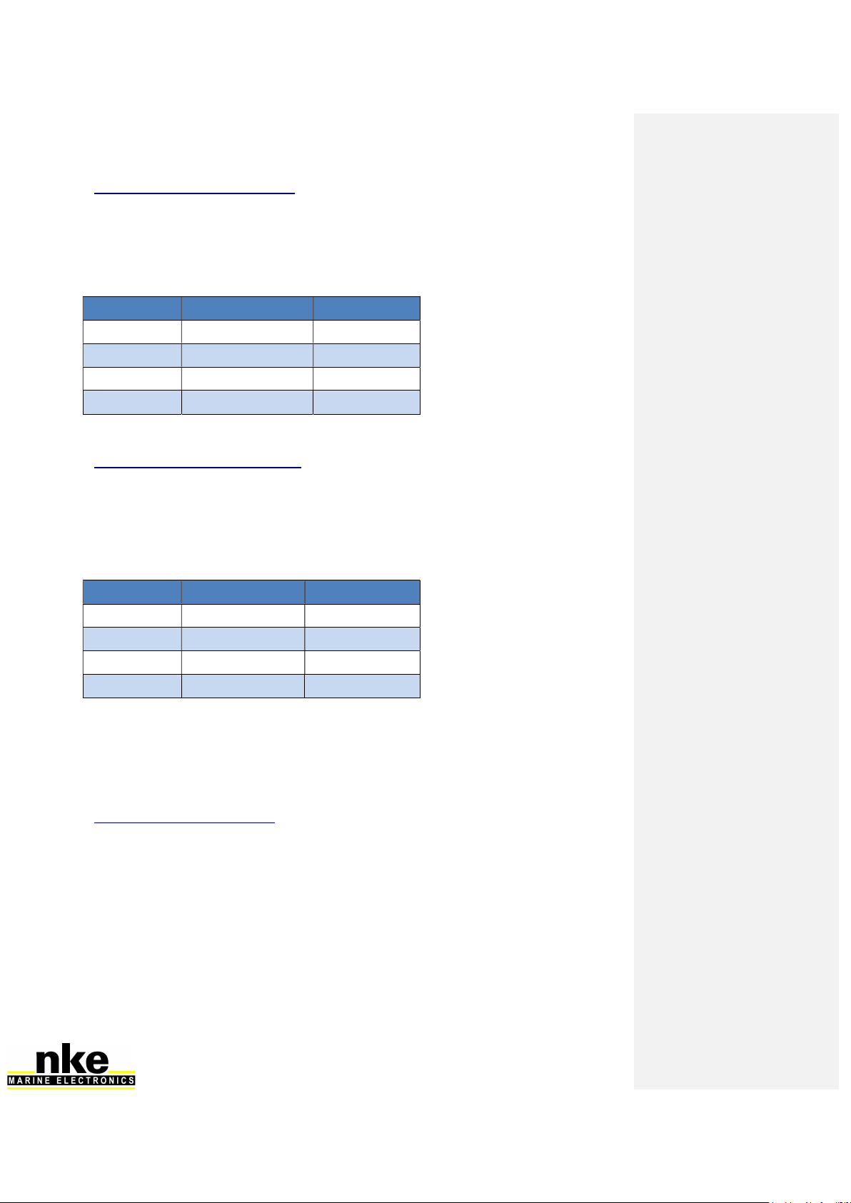
5.6 Connection to the Topline bus
The Processor HR features a Topline plug for connection to the Topline bus which carries
the 12 volts power supply as well.
Cable: twisted pair with aeronautical type shield.
Connector:
Wire Colour
Termination
Blue Topline Data 3 and 5 together
White +12V 4
Shield Common 1
Not connected +5V OUT 2
5.7 Connector 3D Hull and 3D Mast
The 3D Sensor is connecting to the 3D Hull connector.
Cable: 3 wires + aeronautical type shield
Connector: Binder 5 contacts series 620
Cable: 90-60-392 (5 Meters)
Wires Colour
Function
T
ermination
Blue TX Processor 5
White RX Processor 3
Shield Common 1
Orange +12V OUT 4
The 3D Mast is not used.
Please note: Compass Regatta can be powered and communicate with this connector
which can also receive data from the 3D Sensor.
5.8 NMEA1/NMEA2 connectors
These connectors can power and receive data from an NMEA device up to 115kb. Refer to
6. Configuration of the Processor HR for the port configuration.
NMEA1 is an IN/OUT port and NMEA2 is just INPUT port.
Cable: 3 wires + aeronautical type shield
Connector: Binder 5 contacts series 620
Cable: 90-60-522
14 HR_PROCESSOR_um_EN_37
Wire colour
Function
Termination
Termination DB9
Blue TX Processor = RX NMEA
5 2
White RX Processor = TX NMEA
3 3
Shield Common 1 5
Orange +12V OUT 4 Isolate
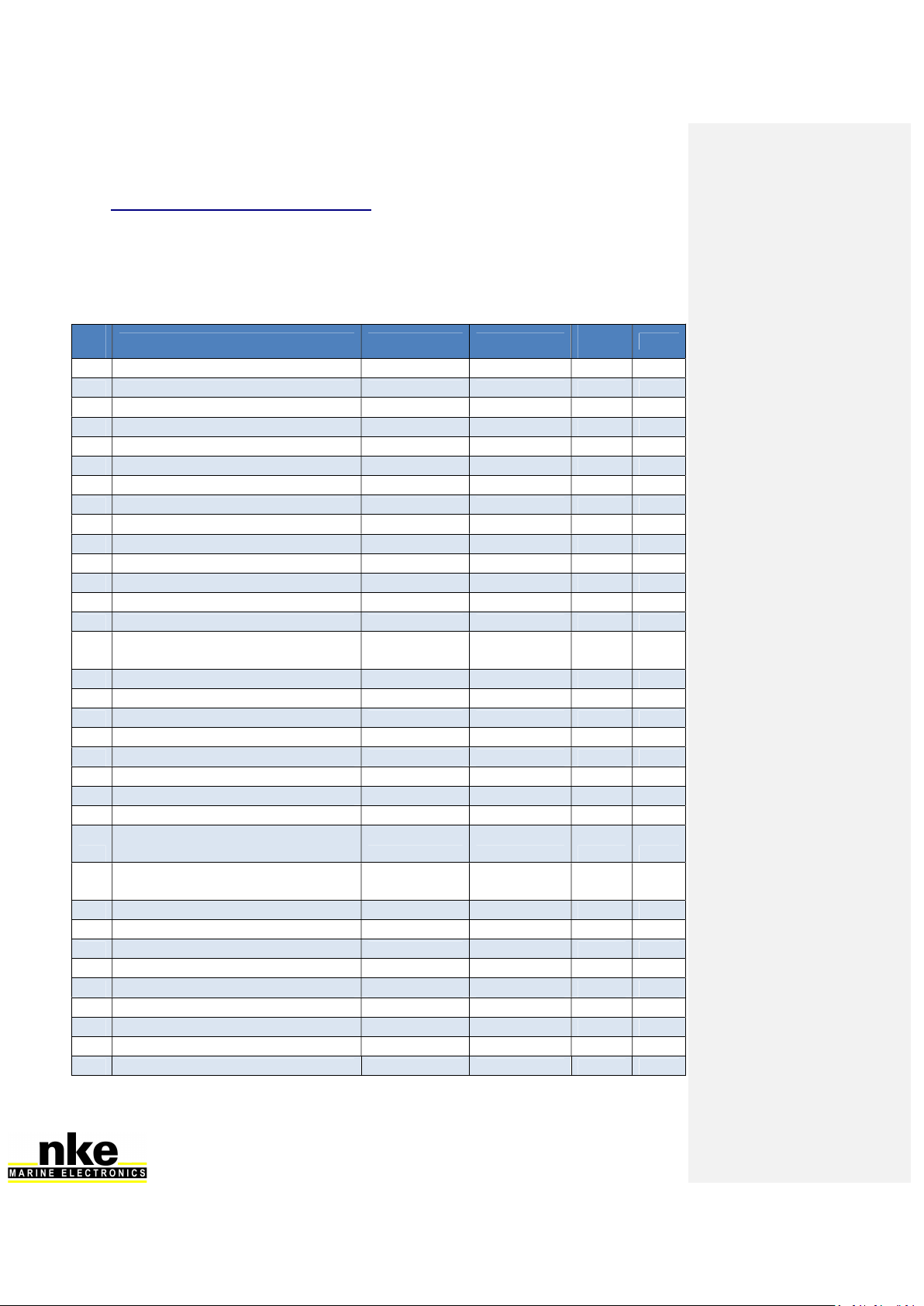
5.9 NMEA input
Below is the list of NMEA sentences accepted by the Processor HR
Each NMEA sentence matches with channels on the Topline bus
Channels are automatically detected. NMEA channels created by the Multigraphic or
Gyropilot Graphic remain as priority input on the NMEA port of the Processor HR
NMEA Code Function
number Possible Functions associated
APB
64 XTE (Cross Track Error)
70 Autopilot status
71 Bearing Origin Waypoint to Destination Waypoint
BOD 71 Bearing Origin Waypoint to Destination Waypoint
BWC 62 Distance to waypoint
63 Bearing to waypoint
BWR 62 Distance to waypoint
63 Bearing to waypoint
CUR 76 Drift (current)
77 Set (current)
DBT 22 Depth
DPT 22 Depth
GGA
86 Latitude Degrees and Minutes
87 Latitude Minutes decimals
88 Longitude Degrees and Minutes
89 Longitude Minutes decimals
GLL
86 Latitude Degrees and Minutes
87 Latitude Minutes decimals
88 Longitude Degrees and Minutes
89
Longitude Minutes decimals
GNS
86 Latitude Degrees and Minutes
87 Latitude Minutes decimals
88 Longitude Degrees and Minutes
89 Longitude Minutes decimals
HDG True Heading - geographical North
198
Magnetic Heading
–
Safe Mode
KVH
198 Magnetic Heading – Safe Mode
199 Heel Angle – Safe Mode
200 Trim Angle – Safe Mode
MDA 48 Air Temperature

15 HR_PROCESSOR_um_EN_37
49 Water Temperature
119 Barometric pressure – High resolution
MMB 119 Barometric pressure – High resolution
MTA 48 Air Temperature
MTW 49 Water Temperature
MWV 192 Apparent Wind Speed – High resolution
193 Apparent Wind Angle – High resolution
RMB
62 Distance to Waypoint
63 Bearing to Waypoint
64 XTE (Cross Track Error)
67 VMG to Waypoint
RMC
27 UTC minutes and seconds
47 UTC Hour and Day
69 UTC Year and Month
86 Latitude Degrees and Minutes
87 Latitude Minutes decimals
88 Longitude Degrees and Minutes
89 Longitude Minutes decimals
208 Speed Over Ground
209 Course Over Ground
ROT 207 Rate of turn and direction of turn.
VBW
21 Boat Speed
42 Dead reckoned drift angle
208 Speed Over Ground
209 Course Over Ground
VDR 76 Drift (current)
77 Set (current)
VHW 21 Boat Speed
118 True Heading - geographical North
VLW 32 Log
31 Trip Log
VTG 208 Speed Over Ground
209 Course Over Ground
VWR 192 Apparent Wind Speed – High resolution
193
Apparent Wind Angle
–
High res
olution
WCV 67 VMG to Waypoint
XTE 64 XTE (Cross Track Error)
70 Autopilot status
XTR 64 XTE (Cross Track Error)
ZDA
27 UTC minutes and seconds
47
UTC Hour and Day
69 UTC Year and Month
ZDL_R 62 Distance to Waypoint
222 Time to Waypoint
ZDL_T 225 Distance to Layline
226 Time to Layline
16 HR_PROCESSOR_um_EN_37
5.10 NMEA sentences input priority rules
A priority order is given to the data coming from the Topline bus on NMEA data.
NMEA sentences from the displays have a priority order on those coming from the
processor.
Each Function can be fed by several NMEA sentences. The table below indicates priority
between NMEA sentences.
Nu
m Variable High Medium High
Mediu
m Low Low
21
Boat Speed VBW VHW
22
Depth DPT DBT
27
UTC minutes and seconds ZDA RMC
32
Log VLW
31
Trip Log VLW
47
UTC Hour and Day ZDA, RMC
48
Air Temperature MTA MDA
49
Water Temperature MTW MDA
62
Distance to Waypoint BWC RMB BWR ZDL_R
63
Bearing to Waypoint BWC RMB BWR
64
XTE (Cross Track Error) RMB APB XTE XTR
67
VMG to Waypoint WCV RMB
69
UTC Year and Month ZDA RMC
70
Autopilot status APB XTE
71
Bearing Origin Waypoint to
Destination Waypoint APB BOD
76
Drift (current) VDR
77
Set (current) VDR
86
Latitude Degrees and Minutes GNS GGA RMC GLL
87
Latitude Minutes decimals GNS GGA RMC GLL
88
Longitude Degrees and Minutes GNS GGA RMC GLL
89
Longitude Minutes decimals GNS GGA RMC GLL
True Heading - geographical North
119
Barometric pressure – High resolution MMB MDA
192
Apparent Wind Speed – High
resolution MWV VWR
193
Apparent Wind Angle – High
resolution MWV VWR
198
Magnetic Heading – Safe Mode KVH HDG
199
Heel Angle – Safe Mode KVH
200
Trim Angle – Safe Mode KVH
207
Rate of turn and direction of turn
ROT
208
Speed Over Ground VBW RMC VTG
209
Course Over Ground VBW RMC VTG
225
Distance to Layline ZDL_T
226
Time to Layline ZDL_T
222
Time to Waypoint ZDL_R
17 HR_PROCESSOR_um_EN_37
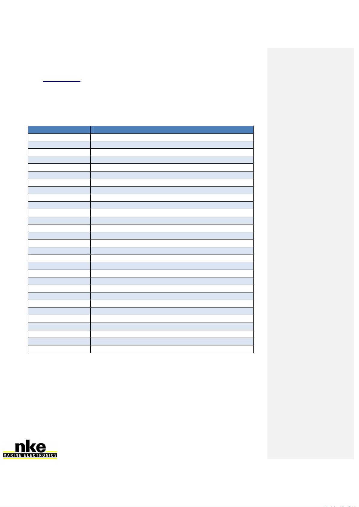
5.11 NMEA output
Output frequency is linked to the baud rate selected.
The table below shows all NMEA sentences that can be output from the processor. An
NMEA sentence will be available for output if at least one value contained in the sentence
is used by the processor.
NMEA sentence Description
$INDBT … Depth below keel
$INDPT … Depth below keel
$INGGA … Global Positioning System Fix Data
$INGLL … Geographic position
$INHDG … Heading – Deviation and Variation
$INHDT … True Heading
$INMTW … Sea Temp
$INMWV,x.x,R … Apparent Wind Angle and Speed
$INMWV,x.x,T … True Wind Angle and Speed
$INMWD …
True Wind Direction and Speed
$INRMB … Recommended Minimum Navigation
$INRMC … Recommended Minimum GNSS Data
$INRSA … Rudder angle
$INVDR … Set and Drift
$INVHW … Water Speed and Heading
$INVLW … Dual Ground/Water Distance
$INVPW … VMG
$INVTG … Course/Speed Over Ground
$INWCV … Waypoint closure velocity
$INXDR …,C,x.x,C,AIRT … Air Temperature
$INXDR …,P,x.x,B,BARO … Barometer
$INXDR …,N,x.x,N,FRST … Forestay
$INXDR …,A,x.x,D,ROLL … Heel angle
$INIXDR ...,H,x.x,P,HYGR … Humidity
$INXDR …,A,x.x,D,KEEL … Keel Angle
$INXDR …,A,x.x,D,LEEW … Leeway angle
$INXDR …,A,x.x,D,MAST … Mast angle
$INXTE … Cross Track Error, measured
$INZDA … UTC Time and Date
18 HR_PROCESSOR_um_EN_37
5.12 Option Connector
No cable is supplied by default. The connector is a Binder 4 contacts series 620
(IP67/snap-in/Dext=11.5mm).
The pin assignment is as follows:
Function
Termination
+12V OUT 1
ACS OUT 3
Pins 1 & 3 + 12V OUT and OUT allow ACS command a
solenoid ( electromagnet, power relays ... ). By default, this output is
dedicated to anti- capsize or keel release system.
Please note: ACS OUT output is open drain type and is limited to 2A / 16V on
a few seconds.

19 HR_PROCESSOR_um_EN_37
6. CONFIGURATION OF THE PROCESSOR HR
In this chapter we will cover the configuration of the Processor HR for your electronics
and information system.
You can access the Processor Regatta home page by typing this address in your Internet
browser: http://192.168.0.232 (refer to addendum A for Computer configuration).
In this page you can find several links to the calibration tools.
6.1 Action of the links
6.1.1 Actions
Reboot processor: Restart the Processor HR
Stop processor: Stop the PROCESSOR HR
Save a backup on the USB stick: Backup all calibrations and tables in USB stick.
Refresh calibrations from the USB stick and restart: Load all backup calibration
parameters and tables from the USB stick and restart the PROCESSOR HR.
6.1.2 Installation and calibrations
Calibrating the constants
The access to the file "Cali.ini" is on the following path:
ftp://root:[email protected]/mnt/flash/processor/constants
Some constants, not accessible from a Display, can be adjusted here. It contains two
sections.
20 HR_PROCESSOR_um_EN_37
[Dampings]
USspdDampLost = 15 ; Filtering speedometer's losses US (seconds)
MastAngDamp = 3 ; Filtering mast angles (table 0..31)
[Constants]
HdgOff = 0.0 ; Additional heading offset (degrees)
MastRotOff = 0.0 ; Mast twist offset (degrees)
MastDeflOff = 0.0 ; Mast tilt/deflection (degrees)
WindShear = 0.0 ; Windshear (degrees)
AWSOff = 0.0 ; Apparent Wind Speed offset (knots)
FailSafeBS = 6.0 ; Spare Boat Speed (knots)
MeasLeewayOff = 0.0 ; Drift sensor offset (degrees)
[MotionWindComp]
WindVaneHigh = 30.0 ; Aerial sensor's height / Rotation centre with heel
(metres)
Coef1 = 6 ; (3DHV2 = 6) (KVH = 4)
Coef2 = 3 ; (3DHV2 = 3) (KVH = 2)
[Anticapsize]
HeelAcsLimit = 35.0 ; Heel angle limit to
prevent capsize (degrees, 0=no)
TrimAcsLimit = 35.0 ; Pitch angle limit to prevent capsize (degrees,
0=no)
AccXAcsLimit = -15 ; m/(s*s).0=no)
AcsConfTime = 0 ; Confirmation time-laps ACS (ms)
AcsCmdTime = 500 ; Command time ACS output (ms)
[PilotHR]
TackingSpeed = 20 ; Rate of turn when tacking /s)
GibingSpeed = 10 ; Turn rate when gybing /s)
SecPerBoomTp = 1 ; Gybing: number of seconds per timeout unit for boom
shift (s)
GibingBoomOff = 0 ; Gybing: Angle offset when the boom shifts over
(degrees)
TackOffset = 5 ; Offset value to catch up speed after tacking
(degrees) -1=disabled
WARNING
The default configuration of this file is correct for 60’ Open but you can apply
modifications should you want to customize your system.
Modifications are saved by pressing « Save File » and will be applied after you reboot
the Processor HR. This is done by pressing « Reboot Processor».
The "Coef" value is entered according to the
sensor connected to the 3Dhull.
This manual suits for next models
1
Table of contents
Other NKE Marine Equipment manuals


