mogk PTP 1450 User manual

Instruction Manual and Operation PTP 1450 –Code 9391 Review 00
THERMAL PRESS SEMIAUTOMATIC
PTP 1450
Version: English - Translation

2
INDEX
1 SAFETY INSTRUCTIONS .........................................................................................................4
1.1 Safety Warnings found in this Manual............................................................................4
1.2 Safety Warnings (Equipment)..........................................................................................4
2 INTRODUCTION........................................................................................................................5
2.1 MOGK's QUALITY POLICE...............................................................................................5
2.2 MOGK's Costumers ..........................................................................................................5
2.3 About the Equipment........................................................................................................ 6
2.4 About the manual..............................................................................................................6
3 GENERAL GUIDELINES...........................................................................................................6
3.1 Receiving, Verifying and Storing.....................................................................................6
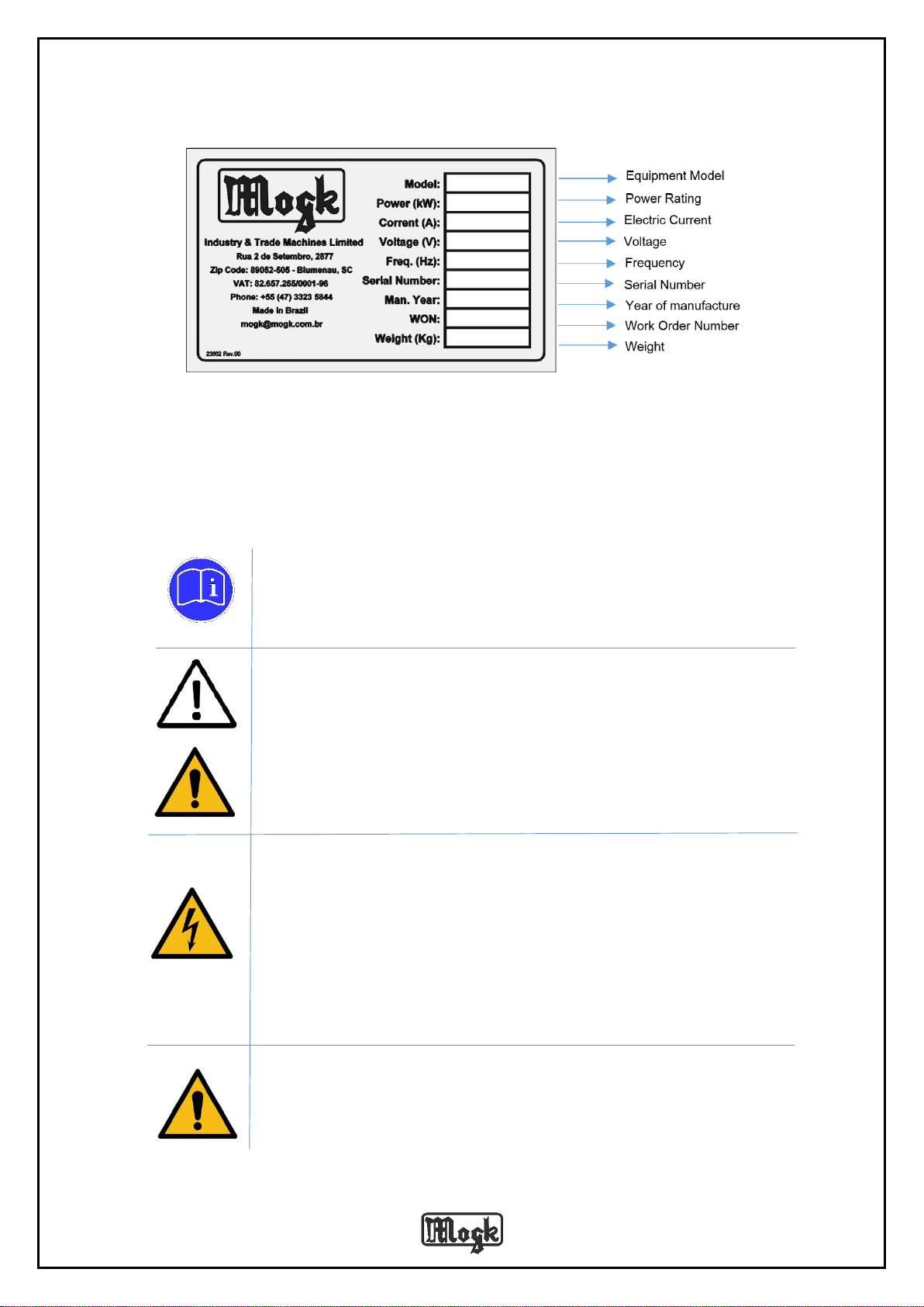
3.2 Identification......................................................................................................................6
4 INSTALLING..............................................................................................................................7
5 COMPRESSED AIR NETWORK CONDITIONS.......................................................................8
5.1 Pneumatic Conexions –Regulating Filter......................................................................8
6 SAFETY (MACHINE).................................................................................................................8
7 OPERATION..............................................................................................................................9
7.1 Operating warning ..........................................................................................................10
7.2 Operating Procedures ....................................................................................................10
7.3 Speed and Pressure Control..........................................................................................11
7.4 Digital Controller –Setting Parameters........................................................................12
8 SECURITY ADHESIVE SIGNS................................................................................................13
9 MAINTENANCE.......................................................................................................................14
9.1 Cleaning...........................................................................................................................14
9.2 Spare Parts ......................................................................................................................14
9.3 Technical Assistance .....................................................................................................15
10 TECHNICAL DATA AND INFORMATION ............................................................................16
11 Pneumatic Scheme ..............................................................................................................17
12 Electric Scheme....................................................................................................................18
12.1 Electric diagram –biphasic 220V................................................................................18
12.2 Electric diagram –three-phase 220V..........................................................................19
12.3 Electric diagram –three-phase 380V..........................................................................20
13 ASSEMBLY DRAWINGS AND SPARE PARTS...................................................................21
13.1 Parts list.........................................................................................................................21
13.2 General Set....................................................................................................................23

3
14 WARRANTY CERTIFICATE..................................................................................................26
15 ANNEX...................................................................................................................................27
15.1 Annex I - Initial Procedure............................................................................................27
15.2 Annex II –Cleaning procedures..................................................................................28
15.3 Annex III –Procedures for Teflon Replacement........................................................29
15.4 Annex IV –Digital Controller .......................................................................................30
15.4.1 Tradution - Digital Controller................................................................................31

4
1 SAFETY INSTRUCTIONS
This guide provides safety instructions in order to present you the correct way.
1.1 Safety Warnings found in this Manual
This manual will show you a few signs such us:
REGULATION
Follow the usage instructions.
DANGER!
Indicates information that, if ignored, could result in personal injury or
even death.
CAUTION!
For safety reasons we discourage any modifications on this equipment.
ATENTION! (TEMPERATURE)
Indicates information that, if ignored, could result in property and health
damages.
DANGER! (ELETRICITY)
Indicates information that, if ignored, could result in serious personal
injury or even death.
1.2 Safety Warnings (Equipment)
The signs below can be found on the equipment and should be considered safety
warnings:
RISK OF ELECTRICAL SHOCK
Electrical current, information that, if ignored, could result in serious
personal injury or even death.

5
RISK!
Only qualified technicians have authorization to install, handle and
maintain this equipment. Follow the safety instructions found in this
manual. The non-observance of this warning could result in death risks and
serious property damages.
EARTH!
This equipment's electric plug has three pins on it and it is the costumer's
responsibility to use de suitable socket with an earth line (center) to avoid
electrical shocks and damages to the equipment.
HOT SURFACE
Hot surface warning
2 INTRODUCTION
2.1 MOGK's QUALITY POLICE
“We are committed to satisfying our customers, bettering our
machines, resistances and our Quality Management System through
our qualified staff and constant valuation of our suppliers”.
2.2 MOGK's Costumers
You have just acquired the THERMAL PRESS SEMIAUTOMATIC PTP-1450 for fabric,
another product with the quality and technology that MOGK produces, made with modern
concepts of design and project.
In order to make the most of your equipment we suggest that you read this manual before
using your new machine.
We hope that this equipment's performance achieves and exceeds the results you
expect.

6
2.3 About the Equipment
The PTP 1450 is a versatile machine with pneumatic drive suitable for:
• Sublimations;
• screen printing transfers;
• termo adhesives embroidery;
• finishing prints;
2.4 About the manual
This manual contains instructions on how to install, operate and identify problems. For
further information and explanation of doubts and specific solutions, please, contact us:
Mogk Industry and Trade Machines Limited.
Rua 2 de Setembro, 2877 - Itoupava Norte
Zip Code: 89052-505 - Blumenau - SC
Phone: +55 47 3323-5844
Fax: +55 47 3323-3172
mogk@mogk.com.br
3 GENERAL GUIDELINES
It is recommended that all staff involved in operating this equipment have read this
manual and its observances. Complying with it will have a direct impact on the performance and
maintenance of your machine.
This manual contains technical information, draws and instructions. MOGK reserves the
right of copy, disclosure and use of it, therefore any of it should not be done without our written
authorization.
If eventually you find any difficulties, please consult us for orientation.
We wish you all the success.
3.1 Receiving, Verifying and Storing
When receiving the equipment please check:
If the information and machine model are correct;
If there is any damage caused by/during the transportation/delivery;
In case of the above mentioned please contact us immediately;
3.2 Identification
This equipment has a nameplate showing all its characteristics and general information.

7
4 INSTALLING
Necessaryrecommendations for installation of THERMAL PRESS SEMIAUTOMATIC PTP 1450:
Install the pneumatic press on perfect leveling conditions without the presence
of aggressive agents.
Keep the machine at a height that meets the anthropometric characteristics of
the operators.
WARNING!
When installing the machine, make sure that the distance between the
calender and the wall of the building, or other machines is insured a minimum
distance of 0.7 meter (70 cm).
Before operating the equipment, perform the assembly of the bench. Pic. 2.
Annex I.
DANGER!
The electrical installation should only be performed by a qualified
professional.
See technical specifications for installation on page 16.
The power supply must be independent and secured according to the rated
power of the machine.
ATENTION!
The air system should provide the necessary conditions for a proper air flow.
See system conditions on page 8.
Picture 1 –Mogk’s nameplate

8
Pneumatic connections must have a filter to prevent the presence of
aggressive agents in the system.
Check the machine's air consumption according to the model specified on
page 16.
Before the daily operation release the water retained in the filter that regulates
the pressure
5 COMPRESSED AIR NETWORK CONDITIONS
The compressed air system must have the necessary conditions for a smooth
flow of the same obeying purity grade of the output air.
Check the room tempoerature and humidity of the site in order to minimize the
condensation of water in the machine's power system.
WARNING!
We recommend using of an automatic purge system with the air dryer.
We recommend using compressor with minimum flow of 10 feet
/ cubic per minute.
5.1 Pneumatic Conexions –Regulating Filter
ATENTION!
In the air inlet of the pneumatic connection there is a filter to prevent the
conduction of aggressive agents in the system. It must be replaced annually.
Filter code: 27563
6 SAFETY (MACHINE)
WARNING!
The PTP 1450model has a security system with fixed barrier within the
pneumatic cylinder action limit preventing access to risk area. Pic. 2

9
DANGER!
The machine cannot be operated without the protections in its surroundings.
It is expressly prohibited the removal of protections, except for maintenance
by an authorized and qualified professional.
Prior to the withdrawal of protective items, the professional who will perform
the maintenance must know the equipment safety procedures.
DANGER!
Only qualified people are authorized to intervene in electrical devices.
The electrical system of the equipment must be regularly checked, always
looking for loose connections and faulty cables, removing them immediately if
found.
The distribution board should be kept closed and the key must be in the
custody of someone entitled by the company.
Access to the distribution board is permitted only by authorized persons.
SAFETY!
Emergency stop devices ensure the immediate stop in case of an emergency
and are allocated in strategic points of the machine for quick access and easy
recognition. The monitoring is performed by the safety relay.
If triggered the drive will remain locked, the reset is performed manually and
only after the correction of the fault. Pic. 2a.
STOPPING THE EQUIPMENT!
The engine stop device (Pic. 2b) ceases the operation without the need of
reseting the process.
7 OPERATION
The PTP 900 is a semiautomatic Printing Machine.
Easy to use, has two trays for prints in 1450 x 1100mm format.
The stamping process is facilitated thanks to the pneumatic system which is practical and cause
less fatigue for the operator.
The top and bottom thermal plates are cast aluminum in order to obtain a uniform temperature
and pressure across the area of the plate.

10
‘
7.1 Operating warning
ATENTION!
Before operating the calender, operators must be enabled, qualified, trained
or authorised.
7.2 Operating Procedures
Plug the power cord to the machine as indicated on page 16;
Turn on the main switch (located on the front of the machine) Pic. 2d
Turn the switch on the machine panel as Pic. 3a,
Push the button to reset the safety drive located on the control panel. Pic. 3c
Picture 2 –PTP 1450 Isometric view
Control panel
Table
Electric panel
A
B
C
C
Manometer
D
E
F

11
to set the process parameters (temperature and time) perform the adjust it
using the digital control panel. Pic.3-D.
Place the protective paper on the felt (Kraft or similar role) and the material to
be worked with on the table (Pic. 2) and position the transfer with the picture
or design facing the material, move the table in the longitudinal direction to the
pressing zone, the pressing process will start, wait for the time selected in the
digital control;
Once finished the LED goes off, the display flashes and the alarm sound
indicates the end of the operation. Slide the table out of the press area and
remove the material.
Keys to Picture 3:
A –Main Switch / Heating On / Off
B –Safaty Enabled - Indicator
C –Reset Button
D –Digital Controller
E –Press Enabled - Indicator
7.3 Speed and Pressure Control
The PTP 900 has a pressure controller located in front of the machine (pic.2) and a rise
speed regulator (pic. 2e) and lowering speed regulation (pic. 2f) of the table.
Set the pressure by turning the handle of the valve half turn at a time;
Turn the handle clockwise to increase pressure;
Turn the handle anti-clockwise to reduce the pressure;
A
Picture 3 –Control panel
B
C
D
F

12
ADVICE!
For transfering using sublimation ink in synthetic material, the lowering of the
table should be slow.
For transfering using sublimation ink in cotton, the lowering of the table should
be fast.
7.4 Digital Controller –Setting Parameters
The pneumatic heat press features programmable digital controller, this device provides
control of temperature and time. Pic.4
ATENTION:
The following procedures must be performed by authorized and qualified staff:
Electrifying the controller:
Press to access programming temperature and and to set the
temperature, after press to save and exit.
Press twice to access time programming (press) and and to set
the time, after press to save and exit.
For further information, see aneex IV.
A
B
C
E
F
D
Picture 4 –Digital Controller

13
Keys for pic. 4:
A –Termocouple’s temperture display
B –Temperature and Time key
C –down: decreases the value
D –up: increases the value
E –Time LED.:Indicates that the timer is on
F –Temperature control LED: indicates that the output control is
enabled
8 SECURITY ADHESIVE SIGNS
The PTP 1450 has safety signs to warn staff and third parties about the risks they are
exposed to.

14
9 MAINTENANCE
ATENTION!
Maintenance should be performed by a qualified person.
DANGER!
Always turn off the power supply before any maintenance.
EARTH
We suggest you to have your machine earthed.
HOT SURFACE
Prior to any maintenance activities, make sure the machine is cold.
9.1 Cleaning
ATENTION!
Switch off the machine before cleaning.
DANGER!
Allow the boards to cool down before cleaning.
To clean the equipment, we recommend using a soft cloth moistened with mild detergent.
Never use solvents (benzenes, ketones, etc.) as it can damage the materials.
9.2 Spare Parts
If necessary the exchange of a part, should be used ORIGINAL PARTS. All equipment
is shipped with a nameplate containing the serial number of the equipment. When requesting
spare parts or repair please have this information in hands.

15
9.3 Technical Assistance
DANGER!
Only people with technical qualifications are authorized to install, operate and
maintenance services of this equipment. All safety instructions in this manual
must be followed. The non-observance of this warning may result in life-
threatening and / or serious damage to property.
WARNING!
For safetyreasons, we do not recommend any modifications to the equipment.

16
10 TECHNICAL DATA AND INFORMATION
VOLTAGE
ELECTRIC
CURRENT
CIRCUIT BREAKER
CONDUCTOR
PHASE /
NEUTRAL
220V TRIPHASE
34 A
10 mm²
50 A
380V TRIPHASE
20 A
4 mm²
40 A
220V MONOPHASE
59 A
16 mm²
80 A
FREQUENCY
60 Hz
POWER
13 kW
TEMPERATURE CONTROL RANGE
0° A 255°C
WEIGHT
650 Kg
USEFUL AREA
145 X 100 cm
DEPTH
3,7 m
WIDTH
1,7 m
HEIGHT
1,5 m
DRIVE
PNEUMATIC
AIR CONSUMPTION
25 liters
SUGGESTED PRESSURE
6 BAR
SUGGESTED COMPRESSOR
10 ft³/min
USEFUL LIFE
8 - 10 years
TYPE OF PAINTING
ELECTROSTATIC
PLATENS MATERIAL
ALUMINUM
WORK ENVIRONMENT TEMPERATURE
0º A 50 °C

17
11 Pneumatic Scheme

18
12 Electric Scheme
12.1 Electric diagram –biphasic 220V

19
12.2 Electric diagram –three-phase
220V

20
12.3 Electric diagram –three-phase
380V
Table of contents
Other mogk Power Tools manuals