MOGlabs MSA User manual

Amplified laser system
Model MSA – internal seed
Model MOA/MOA(L)/MOA(C) – external seed
Revision 2.00

Limitation of Liability
MOG Laboratories Pty Ltd (MOGLabs) does not assume any liability aris-
ing out of the use of the information contained within this manual. This
document may contain or reference information and products protected by
copyrights or patents and does not convey any license under the patent
rights of MOGLabs, nor the rights of others. MOGLabs will not be liable
for any defect in hardware or software or loss or inadequacy of data of
any kind, or for any direct, indirect, incidental, or consequential damages
in connections with or arising out of the performance or use of any of its
products. The foregoing limitation of liability shall be equally applicable
to any service provided by MOGLabs.
Copyright
Copyright ©MOG Laboratories Pty Ltd (MOGLabs) 2017 – 2021. No
part of this publication may be reproduced, stored in a retrieval system,
or transmitted, in any form or by any means, electronic, mechanical, pho-
tocopying or otherwise, without the prior written permission of MOGLabs.
Contact
For further information, please contact:
MOG Laboratories P/L
49 University St
Carlton VIC 3053
AUSTRALIA
+61 3 9939 0677
MOGLabs USA LLC
419 14th St
Huntingdon PA 16652
USA
+1 814 251 4363
www.moglabs.com

Preface
The MOGLabs optical amplifier laser system provides up to 6 W of tun-
able highly coherent optical radiation for atomic cooling, Bose-Einstein
condensation, ion trapping, and other spectroscopic applications. It re-
produces the optical spectrum of the input seed laser, maintaining the
linewidth while increasing the output power by up to 400 times (+26 dB).
It can be configured as amplifier only (MOA) or with seed laser (MSA). Con-
figurations may include input and/or output fibre coupling, and input and
output Faraday isolators. The MOGLabs DLC and LDD drivers are ideally
suited for operating the seed and amplifier components of the amplifier
system.
We hope that the MOGLabs optical amplifier system can work well for your
application. We are proud of our products and continuously improving
them. Please let us know if you have any suggestions for enhancement of
the product or this document, so that we can make life in the lab better
for all.
MOGLabs, Melbourne, Australia
www.moglabs.com
i

ii

Safety Precautions
Your safety and the safety of your colleagues depends on careful atten-
tion to proper operation of this product. Please read the following safety
information before attempting to operate. Please note several specific
and unusual cautionary notes before using the MOGLabs MSA and MOA,
in addition to the safety precautions that are standard for any electronic
equipment. The directions here apply to both MSA and MOA (amplifier-
only) configurations except where explicitly stated otherwise.
WARNING
Do not operate the amplifier above the Maximum current, unseeded
without appropriate input seed. Operation exceeding that condition
can cause fatal structural degradation of the TA diode. Refer to the
Maximum current, unseeded specified in the amplifier test report.
CAUTION
USE OF CONTROLS OR ADJUSTMENTS OR
PERFORMANCE OF PROCEDURES OTHER THAN THOSE
SPECIFIED HEREIN
MAY RESULT IN HAZARDOUS RADIATION EXPOSURE
Laser output from the MSA and MOA can be dangerous. Please ensure that
you implement the appropriate hazard minimisations for your environment,
such as laser safety goggles, beam blocks, and door interlocks. MOGLabs
takes no responsibility for safe configuration and use of the laser. Please:
•Avoid direct exposure to the output beams, both from the injection
seed input aperture and the amplified output aperture.
•Avoid looking directly into either beam.
iii

iv
•Note the safety labels (examples shown in figure 1) and heed their
warnings.
•The MSA or MOA must be operated with a controller with keyswitch
interlock. The MSA must not be powered unless the keyswitch is
inserted and switched on. It should not be possible to remove the
keyswitch without turning off the power to the MSA or MOA.
•When the seed laser and amplifier are switched on, there should
be a delay of two seconds before the emission of laser radiation,
mandated by European laser safety regulations (IEC 60825-1).
WARNING Do not operate the amplifier without sufficient seed laser input. It is
important that an injection seed laser beam is coupled into the ta-
pered amplifier (TA) diode so that most of the electrical input energy
is converted to optical output rather than lost as heat, which would
damage the TA diode.
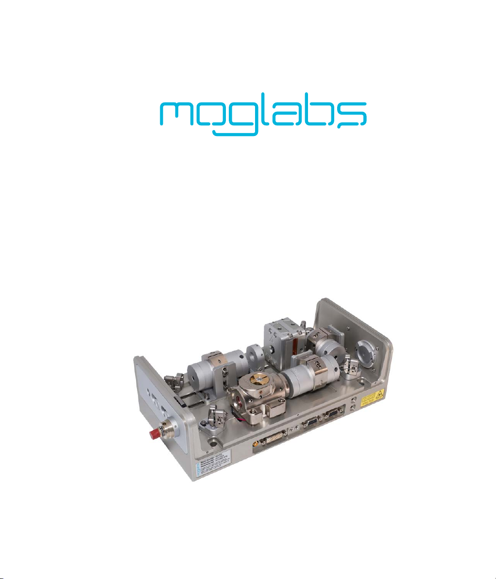
NOTE The MOGLabs MSA and MOA are designed for use in scientific re-
search laboratories. They should not be used for consumer or medical
applications.
Protection Features
The MOGLabs MSA and MOA include a number of features to protect you
and the device. They should be used with a power supply that provides
additional safety features such as key lock operation, current limit, tem-
perature limit, cable continuity and short-circuit detection, soft-start and
turn-on delay.
Protection relay When the power is off, or the temperature controller is
off, the amplifier diode is shorted via a normally-closed relay.
LEDsSeparate LED indicators illuminate when the seed laser and amplifier
diode current supplies are enabled.

v
Label identification
The International Electrotechnical Commission laser safety standard IEC
60825-1:2007 mandates warning labels that provide information on the
wavelength and power of emitted laser radiation, and which show the
aperture where laser radiation is emitted. Figures 1 and 2 show examples
of these labels and their location on the MSA and MOA.
Model number: MSA003
Serial number: A41706001
Manufactured: JUNE 2017
Complies with 21 CFR 1040.10, and 1040.11 except for
deviations pursuant to Laser Notice No.50, dated 24 June 2007
MOG Laboratories Pty Ltd, 49 University St
Carlton VIC 3053, AUSTRALIA
AVOID EXPOSURE
VISIBLE AND INVISIBLE
LASER RADIATION IS
EMITTED FROM THIS APERTURE
Aperture label engraving
US FDA compliance
Warning and advisory label
Class 4
IEC 60825-1:2007
AS/NZS 2211.5:2006
VISIBLE LASER RADIATION
AVOID EYE OR SKIN EXPOSURE TO
DIRECT OR SCATTERED RADIATION
CLASS 4 LASER PRODUCT
Wavelength Max Power
665 − 675nm 600mW
Figure 1: Warning advisory and US FDA compliance labels.

vi
IEC 60825-1:2007
AS/NZS 2211.5:2006
VISIBLE LASER RADIATION
AVOIDEYE OR SKIN EXPOSURE TO
DIRECT OR SCATTEREDRADIATION
CLASS 4 LASER PRODUCT
Wavelength Max Power
665 − 675nm 600mW
IEC 60825-1:2007
AS/NZS 2211.5:2006
VISIBLE LASER RADIATION
AVOIDEYE OR SKIN EXPOSURE TO
DIRECT OR SCATTEREDRADIATION
CLASS 4 LASER PRODUCT
Wavelength Max Power
665 − 675nm 600mW
Emission indicators
Model number:
MSA003
Serial number:
A41706002
Manufactured:
JUNE 2017
Complies with 21 CFR 1040.10, and 1040.11 except for
deviations pursuant to Laser Notice No.50, dated24 June 2007
MOG Laboratories Pty Ltd, 49 University St
Carlton VIC 3053, AUSTRALIA
Model number: MSA003
Serial number: A41706002
Manufactured: JUNE 2017
Complies with 21 CFR 1040.10, and 1040.11 except for
deviations pursuant to Laser Notice No.50, dated 24 June 2007
MOG Laboratories Pty Ltd, 49 University St
Carlton VIC 3053, AUSTRALIA
FDA compliance
and serial number
Laser warning advisor
y
Figure 2: Schematic showing location of warning labels compliant with Inter-
national Electrotechnical Commission standard IEC 60825-1:2007, and US FDA
compliance label. Emission indicator for seed laser (left) and amplifier (right).
Aperture label engraved on front and rear apertures; warning advisory label on
right hand side, compliance label left hand side near exit aperture.

fbookmark[0]Contentsanchor
Contents
Preface i
Safety Precautions iii
1 Introduction 1
2 Safety features 5
2.1 Interlock .............................. 5
2.2 Photodiode safety cutout . . . . . . . . . . . . . . . . . . . . 5
3 First light 7
4 MSA: internal seed alignment 9
4.1 Small adjustment to seed alignment . . . . . . . . . . . . . . 9
4.2 Substantial adjustment to seed alignment . . . . . . . . . . 10
5 MOA: external seed alignment 19
5.1 Seedalignment.......................... 19
5.2 Reverse propagating TA diode beam collimation . . . . . . . 24
6 Output beam optimisation 27
6.1 Procedure for output beam optimisation . . . . . . . . . . . . 28
7 Fibre coupling 31
7.1 Fibre alignment touch-up . . . . . . . . . . . . . . . . . . . . 33
7.2 Fibre alignment procedure . . . . . . . . . . . . . . . . . . . 35
7.3 Fibre coupler collimation . . . . . . . . . . . . . . . . . . . . 38
7.4 Troubleshooting.......................... 39
8 Diode replacement 41
A Electrical connections 45
vii

1. Introduction
The MOGLabs MSA is a semiconductor laser amplifier with injection seed
laser (fig. 1.1). The heart of the system is the amplifier block (fig. 1.2) with
semiconductor tapered amplifier (TA) diode. A cylindrical lens provides
astigmatism compensation and Faraday isolators protect the TA diode, as
well as preventing the amplifier output from disturbing the seed laser.
Figure 1.1: Schematic diagram of major components in the MSA.
The MOA is an amplifier-only configuration of the MSA, without built-in
seed laser. There are two smaller versions of the MOA; the MOA(L) with
one isolator on the TA output and the compact MOA(C) without isolators.
Fibre coupling options are available for the MSA/MOA/MOA(L) output and
for MOA/MOA(L) input with an external seed laser.
The TA diode is mounted in a block (U-chassis) with aspheric input and
output lenses in flexure x−ytranslation stages (fig. 1.2). The flexure
mounts control the transverse positions of the input (focusing) and out-
put (collimation) lenses, providing precise lens alignment with mechanical
1

2Chapter 1. Introduction
stability. Finely threaded tubes control the lens positions along the axis
of propagation. The U-chassis allows simple user replacement of the TA
diode (see chapter 8).
Flexure alignment screws
Focus toolsLens focus
& lock ring
Figure 1.2: TA diode block (U-chassis), showing flexure alignment and focus
adjustments for input and output lenses and tools for focus adjust and locking.
The TA diode emits from both input and output facets. Emission from the
input-side waveguide can be used for seed laser alignment. A tapered
engraving on the side of the U-chassis shows the TA diode orientation,
with the small area ridge waveguide on the input side and large area
tapered waveguide on the output side.
The input lens focuses the seed laser onto the input waveguide of the TA
diode. The output lens collimates the amplified TA laser beam emitted from
the output waveguide.
In normal operation, the seed laser should provide a collimated beam of 10
to 60 mW. The minimum seed power requirement depends on the specific
TA diode, and will be specified in the laser test report. The seed laser
beam should propagate through an input isolator (we recommend >38dB
isolation) and is deflected by mirrors M1 and M2 into the TA diode, with an
optional input isolator between M1 and M2. For the MSA,M1 is a fixed beam
splitter (or polarising beam splitter (PBS) with a half-wave plate before the

3
PBS) to pick off a fixed (or variable) free-space beam from the seed laser,
which can be used for locking to a frequency reference or monitoring the
seed laser. For the MOA series, the seed beam enters through the input
aperture either in free-space or via a fibre coupler, and is then deflected
by mirrors M1 and M2 into the TA diode.
The seed laser beam must be mode-matched to the TA diode. Mode match-
ing can be optimised by ensuring that the reverse propagating TA beam,
emitted from the small area ridge waveguide side of the TA back towards
M2 and M1, is overlapped with the seed beam propagating towards the
TA. The seed and reverse propagating TA beams should have similar beam
size along their paths, and parallel linear polarisation. The MOGLabs am-
plifiers have a zero-order half-wave plate installed for adjusting the seed
polarisation to match the TA diode. Usually the half-wave plate is installed
in the end-cap of the input isolator in MSA systems, or on the chassis for
MOA systems (see figs. 4.1, 4.3 and 5.1).
The main TA output beam propagates through a high-power Faraday iso-
lator. A photodetector (PD) monitors the TA output to ensure that the
TA is properly seeded at high operating currents (see chap. 2 for further
information).
The main TA output exits through the free-space output port or is reflected
by mirrors M3, M4 to a fibre coupler. Replacing M3 with a PBS allows dual
beam output with a variable ratio between free-space and fibre-coupled
outputs. See chapter 7 for details on fibre coupling.
For background information on tapered amplifiers, please see Refs. [1, 2].

4Chapter 1. Introduction

2. Safety features
WARNING
Do not operate the amplifier above the Maximum current, unseeded
without an appropriately coupled input seed. Operation exceeding that
condition can cause fatal structural degradation of the TA diode. Refer to
the Maximum current, unseeded specified in the amplifier test report.
MOGLabs amplifiers have interlocks for customer protection and internal
power monitoring with a safety shutoff feature to protect the TA diode.
The shutoff feature shuts off the TA diode current if simultaneously the
amplifier operates above the Photodiode safety cutout current specified
in the system test report, and the internal power is less than a factory
determined threshold.
2.1 Interlock
An interlock switch located along the top edge of the chassis is activated if
the cover is removed while the TA injection current is above the Maximum
current, unseeded current (see fig. 1.1). The interlock can be defeated
for alignment and test purposes by holding the switch actuator down, for
example with adhesive tape, or by changing the interlock mode under the
headboard settings in the LDD menu.
2.2 Photodiode safety cutout
A photodiode monitors the output power of the TA diode. Once the TA
injection current is above the photodiode safety cutout current, if the out-
put power is measured low for a requested TA diode current, for example
because the seed input has been blocked, the diode current supply will be
switched off to prevent damage to the TA diode.
Two locations for the photodiode are possible. The first location is inside
the exit cover plate of the amplifier U-chassis, which detects light reflected
5

6Chapter 2. Safety features
back from the cylindrical lens. The second location is in a separate mount
with a dedicated fused silica beam-sampling optic.
Please be aware that any changes in optical alignment that affect the
output beam and/or reflected signal from the cylindrical lens will require
re-calibration of the photodiode threshold as described in the LDD user
manual.

3. First light
WARNING
Do not operate the amplifier above the Maximum current, unseeded
without an appropriately coupled input seed. Operation exceeding that
condition can cause fatal structural degradation of the TA diode. Refer to
the Maximum current, unseeded specified in the amplifier test report.
The initial MSA/MOA installation is typically a matter of mounting the
chassis to an optical table, checking the temperature stabilisation and
observing emission of light from the TA diode (and seed laser if MSA).
The MSA/MOA includes a water cooling channel for operation at unusually
high or low temperatures, or in laboratories with high or unstable air
temperature. Quick-fit connectors are provided for connection to 4 mm OD
(optionally 6 mm) tubing, but for most applications, water cooling is not
required; dissipation to the air and/or optical table is sufficient.
Proceed with the following steps for initial installation:
1. The MOGLabs amplifier chassis should be firmly mounted to an opti-
cal table or other stable surface, using the mounting through-holes,
suitable for both metric and imperial tables, accessed by removing
the amplifier cover.
2. The amplifier exit aperture should be directed towards a suitable
power sensor or a beam block.
3. Connect the laser head to a MOGLabs LDD controllers (also to a
MOGLabs DLC if MSA) using the provided cables. For alternative
electronic controllers use the connector pinout description in ap-
pendix A.
4. Enable the temperature controller for the amplifier (and seed) then
check that the temperature readouts are approaching the set points
7

8Chapter 3. First light
indicated on the controllers and specified by in the system test re-
port. Temperature stabilisation usually takes 5 to 10 minutes. De-
tailed LDD and DLC controller operation instructions are provided
separately in their associated user manuals.
5. The TA injection current should be chosen to provide between 10 mW
and 100 mW of output power, but no more than approximately 90%
of the Maximum current, unseeded (refer to customer test report).
Light emission should occur from the TA block output aperture.
NOTE: TA diode operation above Maximum current, unseeded with-
out an appropriately coupled seed laser will damage the diode.
6. For future reference, record a power vs. current (PI) curve for the
main output beam of the unseeded TA diode.
NOTE: Some power sensors (e.g. Si photodiode) have a highly
reflective surface. To avoid damage to the TA diode, ensure the
sensor is not close to normal incidence relative to the TA emission.
7. For MSA systems, power on the seed laser to a suitable current
according to the system test report and wait a minute for thermal-
isation. Record a PI curve for the free space output beam from the
MSA seed. It should be similar to the PI curve in the system test
report (see test report figure Seed power at TA input, pick off). In-
structions for the seed laser operation are provided separately in the
CEL or LDL user manual.
8. For further operation of MSA systems, proceed to chapter 4.
For further operation of MOA systems, proceed to chapter 5.

4. MSA: internal seed alignment
WARNING
Do not operate the amplifier above the Maximum current, unseeded
without an appropriately coupled input seed. Operation exceeding that
condition can cause fatal structural degradation of the TA diode. Refer to
the Maximum current, unseeded specified in the amplifier test report.
WARNING
The isolators contain very strong magnets - much stronger than ex-
pected. Do not bring any e.g. steel objects within 50 mm of the isola-
tors.
4.1 Small adjustment to seed alignment
After initial setup (chapter 3), an MSA system may require a small adjust-
ment to the seed laser alignment. With reference to figure 4.1, optimise
the seed alignment using the procedure outlined below.
1. Ensure proper seed laser operation according to the instructions
provided in the MOGLabs CEL cateye laser user manual.
2. Take note of the Maximum current, unseeded listed in the MSA test
report and the maximum expected output power at this TA current.
3. Terminate the TA output beam path with a power sensor rated to
at least the power noted in step 2, preferably after the isolator at
location Ein fig. 4.1.
NOTE: Measuring the TA output power before isolator could damage
the TA diode with a back-reflection from the power sensor. Take care
to avoid normal incidence reflections.
NOTE: If a sufficiently slim power sensor is not available, insert
a mirror in the beam path after (preferably) or before the output
isolator to deflect the beam to a larger sensor.
9

10 Chapter 4. MSA: internal seed alignment
4. Power on the TA diode with an injection current of 100 mA less than
the Maximum current, unseeded. Adjust the seed laser current/power
so that it matches a listed value from the table Guide for seed cou-
pling at low and high tapered amplifier current in the system test
report, typically 10 mW (20 mW for some TA diodes).
5. Slightly adjust mirror M2 first horizontally, then vertically, to achieve
the maximum possible TA power, PREF . The power should be close
to the value in the table Guide for seed coupling at low and high
tapered amplifier current, either After isolator or Before isolator
column, depending on where the TA output power is measured.
4.1.1 Abbreviated walking procedure
(a) Measure the TA output power while making small (e.g. 1
16 turn)
adjustments to the horizontal axis of M1 until the output power
is maximised.
(b) Adjust only the horizontal axis of M2 to further optimise PREF .
(c) Repeat above two steps until PREF is optimised.
(d) Repeat the above steps for the vertical axis of M1 and M2 until
PREF is optimised.
6. Compare the recorded power of the TA with the appropriate value
from the test report. A variation of 5% is acceptable.
7. Record a TA power vs. TA current curve of the seeded TA diode as a
future reference for comparison if system performance changes.
If the TA output power is far below the factory measured output indicated
in the system test report, proceed to section 4.2.
4.2 Substantial adjustment to seed alignment
Please do not proceed with the alignment steps below unless instructed
to do so in the previous section, there has been substantial seed misalign-
This manual suits for next models
3
Table of contents
Other MOGlabs Laboratory Equipment manuals
Popular Laboratory Equipment manuals by other brands

Tamson Instruments
Tamson Instruments TC16 user manual

Norecs
Norecs ProboStat Supplementary manual

Buchi
Buchi Rotavapor R-220 Pro Continuous Operation manual

Azure Biosystems
Azure Biosystems chemiSOLO user manual

Aqua Medic
Aqua Medic Helix Max Series Operation manual

Thermo Scientific
Thermo Scientific Dionex UltiMate 3000 Series operating instructions