OfiTE 120-55 User manual

Benchtop HTHP Curing Chamber
Part No. 120-55
Instruction Manual
Updated 7/13/2018
Ver. 4.0
OFI Testing Equipment, Inc.
11302 Steeplecrest Dr. · Houston, Texas · 77065 · U.S.A.
Tele: 832.320.7300 · Fax: 713.880.9886 · www.ote.com
©Copyright OFITE 2015

OFITE, 11302 Steeplecrest Dr., Houston, TX 77065 USA / Tel: 832-320-7300 / Fax: 713-880-9886 / www.ote.com 1
Intro..................................................................................................2
Description......................................................................................2
Components ...................................................................................2
Specications .................................................................................3
Setup................................................................................................4
Preparing the Slurry ....................................................................6
Operation.........................................................................................7
Termination .....................................................................................9
Maintenance..................................................................................10
Appendix ....................................................................................... 11
Fuses ........................................................................................ 11
Temperature Controller .............................................................12
Auto Cool ..................................................................................15
Rupture Disc .............................................................................16
Warranty and Return Policy ........................................................17
Table of
Contents

OFITE, 11302 Steeplecrest Dr., Houston, TX 77065 USA / Tel: 832-320-7300 / Fax: 713-880-9886 / www.ote.com 2
The OFITE Benchtop HTHP Curing Chamber is designed to prepare
well cement specimens for compressive strength tests. It is necessary to
determine the amount of time required for a cement to develop compressive
strength so that drilling/production operations can be resumed as quickly as
possible. The goal is to design a slurry that can quickly develop compressive
strength so that the “waiting on cement” time may be minimized. The OFITE
HTHP Curing Chambers provide a means of curing cement specimens under
typical downhole temperatures and pressures.
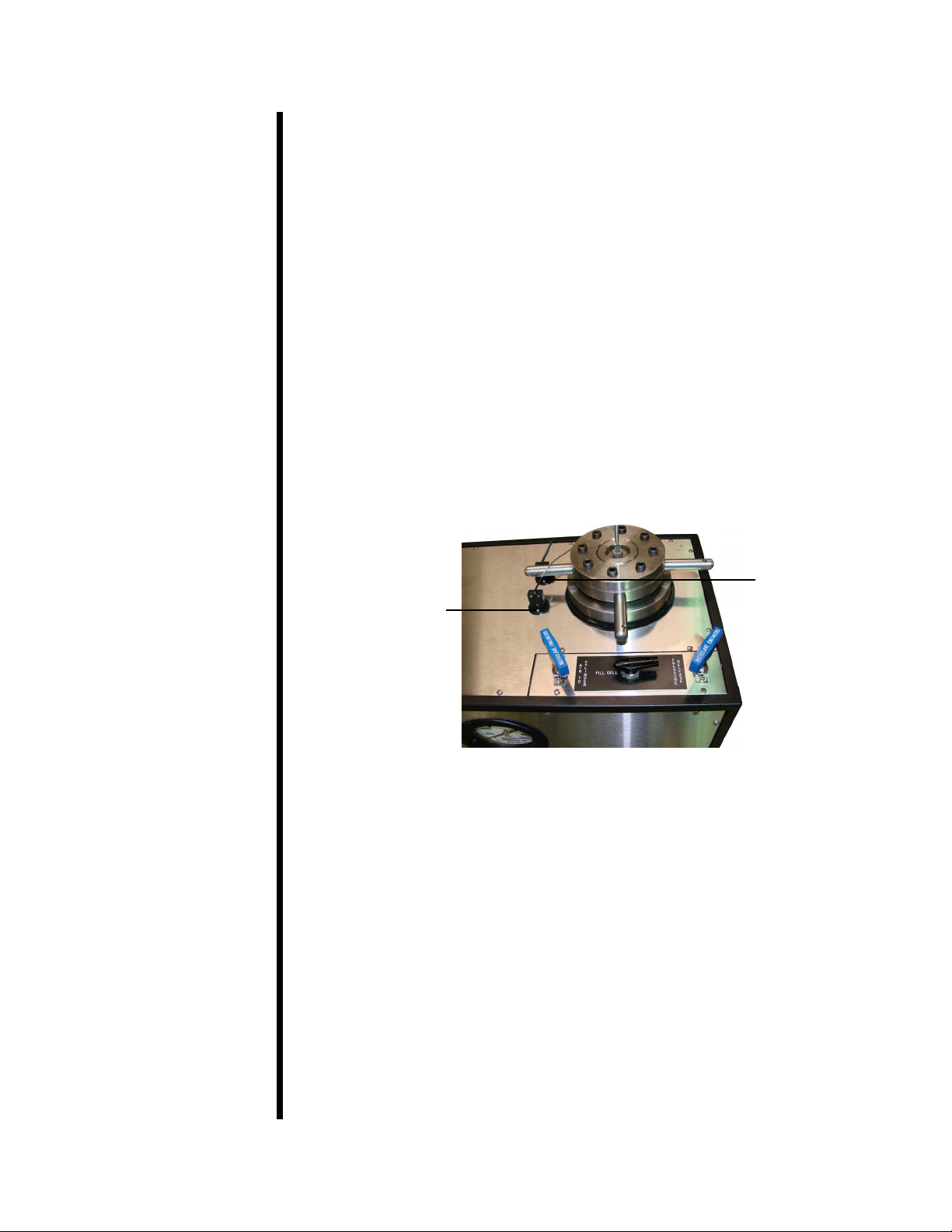
Cement is poured into a special mold that produces specimens measuring
2" × 2"× 2". The mold is placed into the test cell and the pressure is increased
via an air-driven hydraulic pump. Test temperature is governed by a PID
temperature controller, which actuates the heater. After a predetermined
amount of time, the temperature of the test cell is reduced by the cooling
system. Specimens are removed and the compressive strength is determined
as outlined in API Specication 10.
#120-55-005 High-Pressure Filter
#120-55-006 Heater; Thinband; 1,650-Watt; 230-Volt; Qty: 2
#122-052 Rupture Disk; 5,500 PSI (37.9 MPa)
#122-083-1 Cement Mold Assembly, 4 Specimen
#152-38 AC Power Cord; 3-Conductor; International (Continental
European)
Optional:
#120-55-SP Spare Parts for Benchtop Curing Chamber
#120-55-003 Breaker, 16 Amp#120-55-006Heater, Qty: 2
#122-034 Needle Valve, 15K, Qty: 2
#122-052 Rupture Disk, 5,500 PSI, Qty: 2
#122-072 Fuse, 1 Amp, 5 mm × 20 mm, Qty: 8
#122-083-1 Cement Mold Assembly, 4 Specimen
Intro
Description
Components

OFITE, 11302 Steeplecrest Dr., Houston, TX 77065 USA / Tel: 832-320-7300 / Fax: 713-880-9886 / www.ote.com 3
Specications Air Supply Maximum 150 PSI (1035 kPa)
Cooling Water Supply 40 PSI (276 kPa)
Readout Digital
Safety Features Pressure Relief Valve
Safety Head with Rupture Disk
Power Requirements 220 Volts, 50 / 60 Hz, 40 Amp
Weight 215 lb (94.6 kg)
Dimensions 25" × 16" × 20" (63.5 × 40.6 × 50.8 cm)
Shipping Weight 255 lbs (115.8 kg)
Shipping Dimensions 30" × 20" × 24" (76.2 × 50.8 × 61 cm)
Industry Standards API Specication 10, ASTM Standard C-109
Maximum Temperature / Pressure Combinations
Temperature °F (°C) Pressure PSI (kPa)
125 (51.7) 5,250 (36,200)
190 (87.8) 4,800 (33,096)
260 (126.7) 4,400 (30,338)
375 (191) 4,000 (27,600)
400.0 (204.4) 3,800 (26,201)

OFITE, 11302 Steeplecrest Dr., Houston, TX 77065 USA / Tel: 832-320-7300 / Fax: 713-880-9886 / www.ote.com 4
Setup The Benchtop Curing Chamber consists of two modules. The Cell Module
houses the test cell, heaters, and pressure ttings. The Control Module
houses all of the electronic controls and the timer.
1. Carefully remove both modules from the crate.
2. Make sure the “Fill Cell”, “Air to Cylinder”, and “Pressure Release” valves
are closed (turned fully clockwise).
3. Connect a Nitrogen supply (690 – 1,035 kPa or 100– 150 PSI), a water
supply, and a drain line to the designated ¼" (6.35 mm) ports on the back
of the Cell Module.
4. Plug the data cable into the designated ports on the two modules.
5. Plug the thermocouple into the Thermocouple Port on the top of the Cell
Module. Plug the temp data cable (male on both ends) into the Temp Data
Port on the top of the Cell Module. Plug the other end of the cable into the
designated port on the back of the Control Module.
Thermocouple Port
Temp Data Port
6. Make sure all of the switches on the control module are off. Plug the unit
into a grounded electrical outlet.
7. Turn the “Main” switch on.

OFITE, 11302 Steeplecrest Dr., Houston, TX 77065 USA / Tel: 832-320-7300 / Fax: 713-880-9886 / www.ote.com 5
Control Module Control Module
Control Module:
Main Switch - Provides power to the entire unit.
Pump Switch - Provides power to the pump.
Heat Switch - Provides power to the heaters.
Timer Switch - Provides power to the timer.
Auto Cool Switch - Automatically begins cooling at the end of the test.
Sonalert Switch - During an alarm condition, the unit will beep only if this
switch is on.
Cool Switch - Manually begins cooling.
Alarm Switch - If this switch is on, the unit will enter an alarm condition
when the temperature exceeds 400°F (200°C).
Temperature Controller - Controls the temperature in the test. (See
page 12 for instructions)
Timer - Displays the current duration of the test and controls the Auto
Cool function. (See page 15 for instructions)
Cell Module:
Pressure Gauge - Displays the pressure inside the test cell.
Regulator - Controls the pressure inside the test cell. Turn it clockwise to
open and counter-clockwise to close.
Fill Cell Valve - Allows the cell to ll with water, which adds pressure.
Air to Cylinder Valve - Pumps air into the cell to displace the water and
allow it to drain.
Pressure Release Valve - Releases pressure from the cell.
Temperature
Controller
Timer

OFITE, 11302 Steeplecrest Dr., Houston, TX 77065 USA / Tel: 832-320-7300 / Fax: 713-880-9886 / www.ote.com 6
Setup
Preparing the Slurry
It is very important to begin a test as soon as possible after preparing the
cement slurry. Before the slurry is prepared, make sure the unit is ready
to begin a test. If a custom temperature prole is being used, program the
temperature controller (see page 12 for instructions) rst before mixing the
cement.
1. Spread a thin coat of grease on all interior surfaces of the cement molds
(#122-083-1). This will make it easier to remove the cement after the test.
2. Prepare the cement slurry according to API Specication 10.
3. Fill half of each mold with the prepared slurry.
4. With a puddling rod, tap the bottom inside of the cement mold to remove
any trapped air bubbles.
5. Stir the remaining slurry and ll each mold to overowing.
6. Puddle each specimen to remove any trapped air bubbles.
7. Using a straight edge, scrape the excess slurry from the top of each
specimen to make them level.
8. Attach the top plate and secure it in place with the screws provided.
Cement Molds

OFITE, 11302 Steeplecrest Dr., Houston, TX 77065 USA / Tel: 832-320-7300 / Fax: 713-880-9886 / www.ote.com 7
Operation Before beginning a test, make sure all switches are in the off position and all
valves are closed.
1. Loosen all eight set screws on the cell cap with a torque wrench.
2. Unscrew the cell cap and remove it from the cell.
3. Prepare the cement slurry as described on page 6. Carefully lower the
cement molds into the test cell.
4. Remove the handle from the mold.
5. Lubricate the threads of the cell cap with high-temperature thread
lubricant (#165-44).
6. Place the cell cap back onto the cell and screw it in place hand tight. Be
careful not to damage the seal rings and the cap itself.
7. Tighten all the set screws on the cell cap by hand.
8. Adjust the supplied torque wrench to 90 inch-pounds. Tighten the rst
screw until the torque wrench clicks. Skip four screws and tighten the fth
until the torque wrench clicks. Continue in this manner, tightening every
fth screw until all eight have been tightened.
9. Now adjust the torque wrench to 180 inch-pounds and tighten all of the
set screws as described in the previous step.
The cap must be tightened consistently and uniformly every time to
create a good seal.
10. Loosen the thermocouple compression tting in the center of the cell cap.
Insert the thermocouple through the compression tting. Tighten the tting
nger tight and then loosen it ⅛ of a turn.
11. Make sure the “Air to Cylinder” and “Pressure Release” valves are closed.
Turn the “Regulator” completely counter-clockwise.
12. Turn the “Pump” switch on.
13. Open the “Fill Cell” valve. Water will ow into the test cell and the
displaced air will be forced out through the loosened thermocouple
compression tting.
14. Keep a ⅝" wrench handy and watch the top of the cell. When water
begins to ow from the compression tting, tighten it with the wrench. This
will ensure that no air remains in the cell.

OFITE, 11302 Steeplecrest Dr., Houston, TX 77065 USA / Tel: 832-320-7300 / Fax: 713-880-9886 / www.ote.com 8
15. Set the pressure in the test cell by turning the “Regulator” clockwise
until the gauge reads the desired pressure. If the pressure rises too
high, slowly open the “Pressure Release” valve. When the pressure has
dropped, close the valve.
Always release the pressure very slowly to avoid pulling cement into the
plumbing.
16. Set the temperature controller on the Control Module to the desired
temperature.
The temperature controller features both manual and automatic operating
modes. To use the manual mode, simply use the up and down arrows to
set the test temperature. To use the automatic mode, refer to page 12
for instructions.
17. Turn on the “Heater” switch.
18. Turn the “Sonalert” on to be notied of an alarm condition.
19. Program the set points on the timer and press the “F1/RST” button. See
page 15 for more information.

OFITE, 11302 Steeplecrest Dr., Houston, TX 77065 USA / Tel: 832-320-7300 / Fax: 713-880-9886 / www.ote.com 9
Termination When the test is complete, the cement slurry will be fully cured. The system
must be shut down very carefully to avoid injury or damage to equipment.
1. Turn the “Heat” switch off.
2. If “Auto Cool” is off, turn on the “Cool” switch. This will begin circulating
water through the test cell.
3. When the temperature in the cell drops below 180°F (80°C), turn off the
pump and slowly open the “Pressure Release” valve.
Do not attempt to release the pressure until the temperature is below
180°F (80°C).
Always release the pressure very slowly to avoid pulling cement into the
plumbing.
4. Close the “Fill Cell” valve.
5. Slowly open the “Air to Cylinder” valve. This will force the water out of the
cell and into the drain line. When air starts escaping from the drain, close
the “Air to Cylinder” valve.
6. Make sure the pressure gauge reads 0. Slowly loosen the thermocouple
compression tting and remove the thermocouple.
7. Loosen the screws on the cell cap. Unscrew the cap and remove it from
the cell. Remove the cement molds from the cell and allow them to cool
as directed in API Specication 10.
8. Put the cell cap back on the cell to prevent dust and debris from settling
inside. Close all valves and turn all switches off.

OFITE, 11302 Steeplecrest Dr., Houston, TX 77065 USA / Tel: 832-320-7300 / Fax: 713-880-9886 / www.ote.com 10
Maintenance 1. One of the most important elements of trouble free operation is keeping
the interior of the test cell as clean as possible. Never insert a cement
covered cement mold into the test cell and periodically examine the test
cell to ensure that it is clean. High-pressure valves wear quickly when
exposed to uids containing cement and other particulate matter. Also
make sure the air used for the air supply is clear.
2. OFITE uses a high pressure lter to protect valve stems. It is
recommended that ltered water be used in the curing chamber to
prevent particulate matter from entering the pump and possibly causing
damage. Clean or replace these lters when uid ow is reduced
from that of a clean system. Remember: Filters are inexpensive when
compared to the costs of replacing the components they were designed
to protect.
3. The test cell cap threads have been lubricated prior to shipment and
periodically should be re-lubricated.

OFITE, 11302 Steeplecrest Dr., Houston, TX 77065 USA / Tel: 832-320-7300 / Fax: 713-880-9886 / www.ote.com 11
Appendix
Fuses
The Benchtop Curing Chamber uses several fuses and circuit breakers
to protect the electrical components. Each of these should be checked
periodically. The fuses are located inside the Control Module behind the left
side panel. The circuit breakers are located inside the Cell Module behind the
back panel.
1. Main Circuit Breaker - Check if there are any problems with power to
the unit.
2. Heater Circuit Breaker - Check if the unit’s heaters are not functioning.
3. The three fuses in the Control Module are all 1-amp (#122-072). They
each protect different systems within the unit.
- F3: Instruments and Cooling
- F4: Pump, Heat, and Sonalert
- F5: Main Relay
Main Circuit Breaker
Heater Circuit Breaker
Fuses

OFITE, 11302 Steeplecrest Dr., Houston, TX 77065 USA / Tel: 832-320-7300 / Fax: 713-880-9886 / www.ote.com 12
Appendix
Temperature Controller
The controller allows the temperature prole to be programed for each test.
This prole will be divided into at least two segments. Each segment controls
a portion of the test and determines the temperature, time, and behavior of
the test cell during a specied time period.
The four buttons along the bottom of the display provide access to the
temperature proles. Begin by pressing the “PAGE” button three times. The
display will read “Prog List”. Now, press the “SCROLL” key repeatedly until
the setting you wish to change is shown on the display. Then press either
arrow key until the appropriate value is displayed. Once a value has been
chosen, press the “SCROLL” key again to select a new setting.
The rst group of settings should read as follows:
Setting Value
Prg1 1
Hb OFF
Hb.u 0.0
Rmp.u min
Dwl.u min
Cyc.n 1
These settings will be the same for every test. Do not change them.
1. Begin by dening the rst segment of the test.
a. Press the “SCROLL” key repeatedly until “Seg” appears on the display.
b. Press either arrow key repeatedly until “1” appears on the display.
This is now editing segment 1.
2. The rst setting is “Type”.
a. Press the “SCROLL” key until the word “Type” appears on the display.
b. The available options are “rmp.r”, “rmp.t”, or “dwell”. Press either arrow
key until the appropriate value appears on the display.
Rmp.r programs the controller to steadily increase the temperature by
a specied rate (degrees per minute). If this value is chosen, the next
option will be “Tgt”, which is the target temperature and then “Rate”
which is the desired rate the temperature will increase.
Rmp.t increases the temperature over a specied time interval
(minutes). If this valueis chosen, the next option will be “Tgt” (target
temperature) and then “Dur” (duration in minutes).
Dwell holds the temperature at its current setting for the duration
specied.

OFITE, 11302 Steeplecrest Dr., Houston, TX 77065 USA / Tel: 832-320-7300 / Fax: 713-880-9886 / www.ote.com 13
Temperature Controller
RUN/HOLD
Page Scroll
3. Now dene the second segment.
a. Press the “SCROLL” key until “Seg” appears on the display.
b. Press either arrow key until “2” appears on the display. This is now
editing segment 2.
3. Continue this process with each segment in the test.
4. When you reach the last segment, set the “Type” to “end”. The next
setting will be “End.t”.
If “sop”is chosen, the heat will turn off and the test will end.
If “dwell” is chosen, the heat will hold at the current temperature
indenitely.
Example 1:
Heat the sample at 2.5° per minute and stop at 150°. Hold at 150° for 180
minutes and then stop the heat.
Setting Value Description
Prg 1
Hb OFF
Hb.u 0.0
Rmp.u min
Dwl.u min
Cyc.n 1

OFITE, 11302 Steeplecrest Dr., Houston, TX 77065 USA / Tel: 832-320-7300 / Fax: 713-880-9886 / www.ote.com 14
Seg 1 Segment 1
Type rmp.r Increase temperature at a specied rate
Tgt 150 Heat to 150°
Rate 2.5 Increase temperature at 2.5° per minute
Seg 2 Segment 2
Type dwell Hold on the current temperature
Dur 180 Hold for 180 minutes
Seg 3 Segment 3
Type end This is the last segment
End.t sop Stop the heat
Example 2:
Heat the sample to 200° over a period of 90 minutes. Then increase the
temperature to 300° at a rate of 3° per minute. Hold that temperature
indenitely.
Setting Value Description
Prg 1
Hb OFF
Hb.u 0.0
Rmp.u min
Dwl.u min
Cyc.n 1
Seg 1 Segment 1
Type rmp.t Increase temperature for a specied time
Tgt 200 Heat to 200°
Dur 90 Increase temperature for 90 minutes
Seg 2 Segment 2
Type rmp.r Increase temperature at a specied rate
Tgt 300 Heat to 300°
Rate 3 Increase temperature at 3° per minute
Seg 3 Segment 3
Type end This is the last segment
End.t dwell Hold at the current temperature indenitely

OFITE, 11302 Steeplecrest Dr., Houston, TX 77065 USA / Tel: 832-320-7300 / Fax: 713-880-9886 / www.ote.com 15
Appendix
Auto Cool
The OFITE Curing Chamber incorporates a timer for auto-cooling. The timer
may be activated by turning the “TIMER” switch to the on position.
As an example, suppose the temperature is ramping up to 350°F in one hour
and maintaining for four hours. After the test, allow it to cool for two hours.
1. Press the key to select setpoint 1. The setpoint number is in the
bottom left-hand corner of the display.
2. Press the up and down arrows to set the setpoint. Remember to set
the timer for the number of minutes. In this example, set it to 300
(equivalent to 5 hours).
3. Press the key to select setpoint 2.
4. Press the up and down arrows to set the setpoint. Remember to set
the timer for the total number of minutes for the test. In this example,
set it to 420 (5 hours of heating plus 2 hours of cooling).
5. Press the key again to return to the home screen.
6. Press the F1/RST button to start the timer. Make sure the “AUTO
COOL” switch is in the “ON” position. After 5 hours the water solenoid
will engage and begin cooling the unit. The unit will cool for 2 hours
and then the solenoid would de-activate.
While running, the timer counts in minutes. It may not immediately
appear to be working. But after one minute, the readout will advance
to 2.
F1
RST
Timer Front Panel Layout

OFITE, 11302 Steeplecrest Dr., Houston, TX 77065 USA / Tel: 832-320-7300 / Fax: 713-880-9886 / www.ote.com 16
Appendix
Rupture Disc
The Curing Chamber is assembled with a rupture disk (#122-052) which is
rated for a maximum of 5,500 PSI. It is a solid metal preformed differential
pressure relief device which is used to protect the system from an
overpressure condition. The rupture disk provides instantaneous full-opening
within milliseconds of an overpressure situation.
The main symptom of a blown rupture disk that the system will not be able to
build pressure.
The rupture disk is located in the back side of the Curing Chamber.
To replace the rupture disk:
1. Turn the Curing Chamber off and depressurize the air system.
2. Use a phillips head screwdriver to remove the rear panel.
3. Use a ⅝" wrench to remove the top and bottom tube ttings to the high
pressure tee.
4. Use a 9/16" wrench to remove the high pressure tee assembly from the
outlet tube tting.
5. Orient the tee assembly so that the outlet port faces up.
6. Use two adjustable wrenches to remove the outlet tting and gain access
to the rupture disk.
7. Replace the rupture disk (#122-052), reassemble the housing, and
reinstall the tee assembly to the tubing.
8. Replace the rear panel.
Adjustable Wrench ⅝"
Outlet Fitting 9/16"
Rupture Disk
High Pressure Tee

OFITE, 11302 Steeplecrest Dr., Houston, TX 77065 USA / Tel: 832-320-7300 / Fax: 713-880-9886 / www.ote.com 17
Warranty and
Return Policy
Warranty:
OFI Testing Equipment, Inc. (OFITE) warrants that the products shall be free from liens and defects in
title, and shall conform in all respects to the terms of the sales order and the specications applicable
to the products. All products shall be furnished subject to OFITE’s standard manufacturing variations
and practices. Unless the warranty period is otherwise extended in writing, the following warranty
shall apply: if, at any time prior to twelve (12) months from the date of invoice, the products, or any
part thereof, do not conform to these warranties or to the specications applicable thereto, and OFITE
is so notied in writing upon discovery, OFITE shall promptly repair or replace the defective products.
Notwithstanding the foregoing, OFITE’s warranty obligations shall not extend to any use by the buyer
of the products in conditions more severe than OFITE’s recommendations, nor to any defects which
were visually observable by the buyer but which are not promptly brought to OFITE’s attention.
In the event that the buyer has purchased installation and commissioning services on
applicable products, the above warranty shall extend for an additional period of twelve
(12) months from the date of the original warranty expiration for such products.
In the event that OFITE is requested to provide customized research and development for the buyer,
OFITE shall use its best efforts but makes no guarantees to the buyer that any products will be provided.
OFITE makes no other warranties or guarantees to the buyer, either express or implied,
and the warranties provided in this clause shall be exclusive of any other warranties
including ANY IMPLIED OR STATUTORY WARRANTIES OF FITNESS FOR PURPOSE,
MERCHANTABILITY, AND OTHER STATUTORY REMEDIES WHICH ARE WAIVED.
This limited warranty does not cover any losses or damages that occur as a result of:
• Improper installation or maintenance of the products
• Misuse
• Neglect
• Adjustment by non-authorized sources
• Improper environment
• Excessive or inadequate heating or air conditioning or electrical
power failures, surges, or other irregularities
• Equipment, products, or material not manufactured by OFITE
• Firmware or hardware that have been modied or altered by a third party
• Consumable parts (bearings, accessories, etc.)
Returns and Repairs:
Items being returned must be carefully packaged to prevent damage in
shipment and insured against possible damage or loss. OFITE will not be
responsible for equipment damaged due to insufcient packaging.
Any non-defective items returned to OFITE within ninety (90) days of invoice are subject to a
15% restocking fee. Items returned must be received by OFITE in original condition for it to
be accepted. Reagents and special order items will not be accepted for return or refund.
OFITE employs experienced personnel to service and repair equipment manufactured by us, as
well as other companies. To help expedite the repair process, please include a repair form with all
equipment sent to OFITE for repair. Be sure to include your name, company name, phone number,
email address, detailed description of work to be done, purchase order number, and a shipping address
for returning the equipment. All repairs performed as “repair as needed” are subject to the ninety (90)
day limited warranty. All “Certied Repairs” are subject to the twelve (12) month limited warranty.
Returns and potential warranty repairs require a Return Material Authorization (RMA)
number. An RMA form is available from your sales or service representative.
Please ship all equipment (with the RMA number for returns or warranty repairs) to the following address:
OFI Testing Equipment, Inc.
Attn: Repair Department
11302 Steeplecrest Dr.
Houston, TX 77065
USA
OFITE also offers competitive service contracts for repairing and/or maintaining your lab
equipment, including equipment from other manufacturers. For more information about
our technical support and repair services, please contact techservice@ote.com.
Table of contents
Other OfiTE Laboratory Equipment manuals
Popular Laboratory Equipment manuals by other brands

Beckman Coulter
Beckman Coulter CytoFLEX LX manual

D-Link
D-Link DKT-200 Quick installation guide

Thermo Scientific
Thermo Scientific Cryostat Microm Cryo-Star HM 560 instruction manual

Merck
Merck Millipore DiluCult quick start guide

BioLAB
BioLAB BCLT-203 Operation manual

Memmert
Memmert HPPeco quick start guide

Thermo Scientific
Thermo Scientific Arctic Express CY50900 Operation manual and parts list

GOLDENSEA UV
GOLDENSEA UV UVS4 quick start guide

R-Biopharm
R-Biopharm RIDA qLine autoBlot user manual

VWR
VWR Powerpette Pro instruction manual

GE
GE pH/C-900 operating instructions

fine bubble
fine bubble MK1 NANO BUBBLER Operation and maintenance manual