MOLEAER CLEAR Installation manual

CLEAR INSTALLATION AND STARTUP GUIDE REV. B
REFER TO OPERATING MANUAL FOR IMPORTANT SAFETY INFORMATION

PAGE INTENTIONALLY LEFT BLANK

Rev. B
i
TABLE OF CONTENTS
TABLE OF CONTENTS................................................................................................................i
GENERAL INFORMATION..........................................................................................................1
LOCATION REQUIREMENTS.....................................................................................................1
PARTS AND ACCESSORIES......................................................................................................3
INSTALLATION GUIDELINES.....................................................................................................4
Installation Parts and Materials.................................................................................................4
Pipe Assembly..........................................................................................................................4
Clear Installation.......................................................................................................................4
Suction Piping and Intake Structure Installation........................................................................6
Discharge Piping Installation ....................................................................................................7
QUICK STARTUP GUIDELINES..................................................................................................7
Power Input Instructions...........................................................................................................8
Pump Priming Instructions........................................................................................................8
Suction and Discharge Operation.............................................................................................9
Typical Operating Parameter Ranges.....................................................................................10
Document Revision History........................................................................................................11
APPENDIX: RECOMMENDED INSTALLATION/OPERATING ENVELOPE ..............................13
APPENDIX: INSTRUCTIONS FOR SOLVENT WELDING PVC PIPES .....................................16

Rev. B
ii
PAGE INTENTIONALLY LEFT BLANK

Rev. B
1
GENERAL INFORMATION
Read instructions thoroughly prior to assembly and installation. All Clear products are factory
adjusted for optimal nanobubble production. Do not adjust factory setpoints.
LOCATION REQUIREMENTS
Carefully select the Clear installation location based on the requirements specified in this section.
Locate the Clear as close to the waterbody as possible in a 5 ft x 5 ft (1.5 m x 1.5 m) open area
of level ground. Use the guidelines shown in Figures 1 and 2 to locate the intake structure.
Ensure that the intake structure location is free of weeds and debris. Do not locate the intake
structure in an area where leaves or other floatable debris tend to accumulate. Where possible,
locate the intake structure several feet (a couple of meters) from shore.
Figure 1: Plan View of Clear Suction and Discharge Pipe Installation
Figure 2: Section View of Clear Suction and Discharge Pipe Installation

Rev. B
2
For Clear power input, suction and discharge pipe, and installation elevation requirements refer
to Tables 1, 2, and 3, respectively. Tables are divided by pump type, if applicable.
Failure to install the Clear within the limits specified in Tables 1, 2 and 3 may void the
system warranty and result in poor nanobubble production and pump cavitation.
Table 1. Power Input Requirements
Clear 50*
Clear 150*
60 Hz (North America)
Single Phase, 115 V or 220-240 V
Single Phase, 220-240 V
50 Hz
Single Phase, 220-240 V
*Check pump nameplate to verify power input requirements.
Table 2. Suction and Discharge Pipe Requirements
Clear 50
Clear 150
Nominal Pipe Size
2 in (63 mm)
3 in (90 mm)
Equipped Pump Brand:
Pentair Sparus 160
Maximum Suction Pipe Length
350 linear ft (106.7 linear m)
250 linear ft (76.2 linear m)
Maximum Total Pipe Length
(Suction + Discharge)
700 linear ft (213.4 linear m)
500 linear ft (152.4 linear m)
Equipped Pump Brand:
DAB ESWIM
Maximum Suction Pipe Length
400 linear ft (122.0 linear m)
Maximum Total Pipe Length
(Suction + Discharge)
800 linear ft (243.9 linear m)
Table 3. Installation Elevation Requirements
Clear 50
Clear 150
Equipped Pump Brand:
Pentair Sparus 160
Recommended Suction Lift*
13 vertical ft (4 vertical m)
6 vertical ft (1.8 vertical m)
Equipped Pump Brand:
DAB ESWIM
Recommended Suction Lift*
16 vertical ft (4.9 vertical m)
12 vertical ft (3.7 vertical m)
*Vertical distance between minimum water line of water body and base of Clear.
Pipe lengths and unit elevations can play an important role in the performance of the pump and
the unit as a whole. Refer to the Appendix for additional detail regarding the recommended
operating envelope for these units.
While minimizing the elevation of the unit from the water surface is the key to optimized
performance, special measures must be taken to reduce the chances of water ingress
into the unit (flooding). For example, if the water level changes throughout the year, the
installation elevation must be above the max water level. If the water ingress is
unpredictable, use barriers around the unit to reduce the chance of flooding.

Rev. B
3
PARTS AND ACCESSORIES
The parts and accessories shown in Table 4 are shipped loose with all Clear products.
Table 4. Clear Standard Parts List
Image
Quantity
Clear 50
Clear 150
Part Description
1
2 in
3 in
Intake Screen with Check Valve
1
One Size
One Size
Intake Screen Stand
All parts necessary to assemble up to 40 linear feet (12 linear meters), each, of suction and
discharge piping are provided with purchase of a Clear Installation Kit. The actual length of pipe
required will vary by installation. Additional pipe lengths may be purchased with the Clear in
10-foot (3-meter) increments.
The Clear Installation Kit can only be shipped within the United States and Canada. Refer to
Table 5 for the Clear Installation Kit parts list. Clear Installation Kit parts and additional suction
and discharge pipe can be purchased at most hardware stores. For pipe assembly, use only
Schedule 40 polyvinyl chloride (PVC) pipe and fittings and Oatey Rain-R-Shine Medium
Blue PVC Cement or equivalent PVC cement formulated for wet conditions and fast
installation.
Prior to installation, verify all parts listed in Tables 4 and 5 are present. Not all pipe and fittings
provided in the Clear Installation Kit will be required for all installations.
Table 5. Clear Installation Kit Parts List
Clear Installation Kit Parts List
Image
Quantity
Clear 50
Clear 150
Part Description
1
8 oz
8 oz
PVC Pipe Primer
1
8 oz
8 oz
PVC Cement Formulated for Wet
Conditions and Fast Installation
8
2 in NPS x
10 ft Length
3 in NPS x
10 ft Length
Sch 40 PVC Bell-End Pipe
6
2 in
3 in
Sch 40 PVC Couplings with Socket
Ends
6
2 in
3 in
Sch 40 PVC 45 Street Elbow with
Socket Ends
6
2 in
3 in
Sch 40 PVC 90 Street Elbow with
Socket Ends

Rev. B
4
INSTALLATION GUIDELINES
The unique site conditions for each waterbody should be carefully considered when identifying
the Clear installation location. Refer to the Location Requirements section of this guide for
addition details.
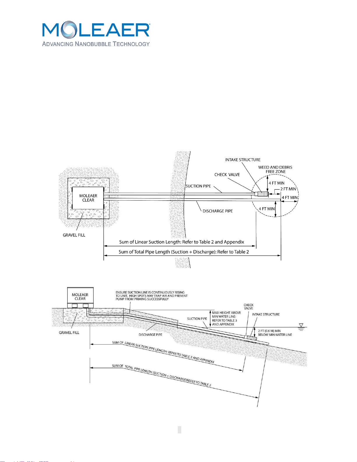
The guidelines herein are recommended for calm waterbodies with intake structure depths less
than 10 ft (3 m). For deeper water intakes or high current waterbodies, contact a Moleaer
sales representative or call (424) 558-3567 prior to purchasing a Clear.
Upon delivery, unscrew the shipping screws to remove the Clear from the shipping crate. Inspect
the Clear for any damage or loose parts that may have occurred during transport. Hand tighten
any loose parts.
Installation Parts and Materials
The parts and materials required to install the Clear include:
•A shovel
•25 cubic feet (0.7 cubic meters) of all-purpose gravel
•PVC saw
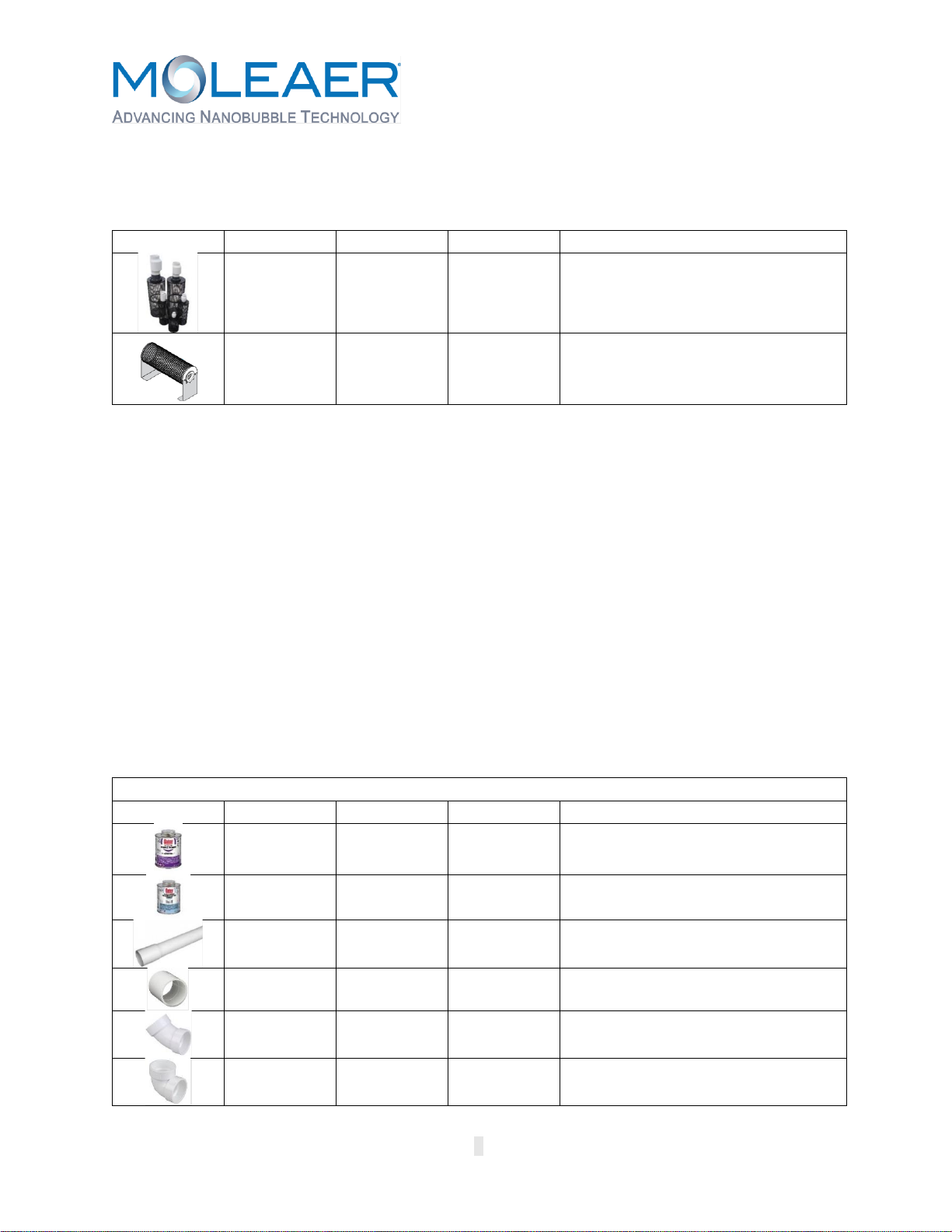
•PVC pipe primer and PVC pipe cement
•Clear Installation Kit or installation kit parts listed in Table 5
Pipe Assembly
Completely bury or submerge all PVC pipe and fittings to avoid ultraviolet (UV)
degradation. All PVC pipe connections must be solvent welded using PVC cement. Use
only Schedule 40 polyvinyl chloride (PVC) pipe and fittings. Use only PVC cement formulated for
wet condition and fast installation to connect PVC pipe to PVC fittings. Do not use black,
acrylonitrile butadiene styrene (ABS) piping or mix ABS pipe or fittings with PVC pipe or fittings.
All PVC pipe connections must be airtight and leakproof. Failure to provide airtight suction
pipe connections may negatively impact nanobubble generator performance. Large
bubbles visible at the pump strainer basket is an indication of suction pipe leaks. Difficulty with
pump priming may also be an indication of suction pipe leaks. Check and correct for all suction
and discharge pipe leaks prior to burying or submerging pipe.
Proper technique must be used when gluing PVC pipe and fittings to ensure an airtight, leakproof
connection. For proper technique, refer to the Appendix. Allow for proper cure time to lapse
before wet testing suction and discharge pipes. Refer to Appendix, Item 8 for cure times.
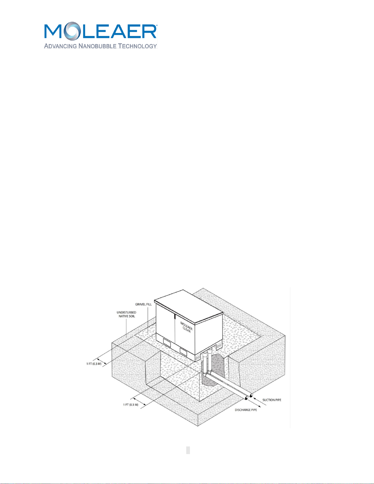
Clear Installation
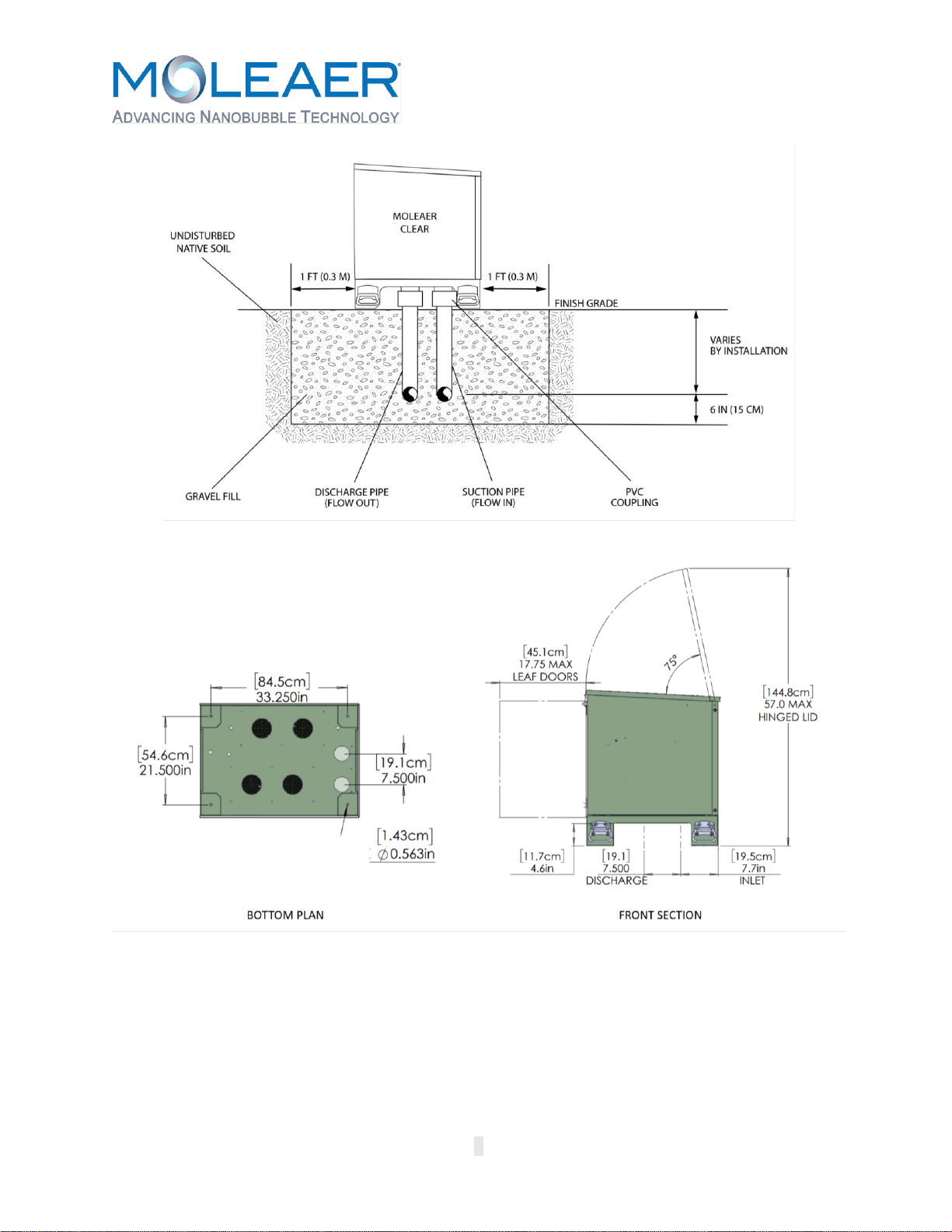
The installation diagrams for the Clear are shown in Figures 3 and 4. Using a shovel, dig a hole
approximately 5 ft (1.5 m) Long (L) x 5 ft (1.5 m) Wide (W) x 1 ft (0.3 m) Deep (D). The Clear will
be installed with the pressure gauges facing away from the waterbody. Near the edge of the hole

Rev. B
5
that is closest to the waterbody, dig out a portion of the pipe trench that is long and deep enough
to hold the first segment of suction and discharge pipe.
Refer to the pipe connections extending from the base of the Clear that are shown in Figure 3.
Using PVC primer and cement, glue elbows to the first straight, horizontal pipe segments of
suction and discharge piping and lay these pipe segments in the pipe trench with the elbows
facing up. Refer to Figure 5 for Clear enclosure dimensions and pipe penetration locations to
properly position the elbows.
Using PVC pipe primer and cement, glue a segment of straight pipe long enough to vertically
connect the pipe connections at the base of the Clear to the elbows positioned in the hole. Glue
one end of the vertical pipe to the suction elbow in the trench and the other end to a coupling.
Repeat these steps for the vertical segment of discharge pipe. Do not bury horizontal pipes until
the Clear is installed and has passed leak inspection and wet testing.
Once the vertical suction and discharge pipes and first segments of horizontal suction and
discharge pipes are glued in position, fill the hole with gravel until the reducing couplers are
partially buried. Level the gravel. Verify the reducing couplers are positioned correctly to line up
with the pipe connections extending from the base of the Clear.
The pipe connections at the base of the Clear are grooved for factory testing. The grooves will
not interfere with the gluing of PVC connections. Using PVC primer and cement, coat the pipe
connections at the base of the Clear and the reducing couplers with cement and then place the
Clear on the gravel bed, making sure that the pipe connections are aligned with and firmly glued
into the coupling.
Figure 3: Clear Isometric Installation Diagram

Rev. B
6
Figure 4: Clear Front Section Installation Diagram
Figure 5: Clear Enclosure Dimensions
Suction Piping and Intake Structure Installation
Locate and install the intake structure and suction pipe following the recommendations detailed
in Figures 1, 2, and 6, and in the Appendix. Use available fittings as necessary to route the
suction piping from the Clear to the waterbody. Do not remove the bell end of the PVC pipe. The
bell end can be used as a coupling for connecting straight pipe segments.

Rev. B
7
The intake structure consists of the intake screen, check valve, and stand as shown in Table 4.
To assemble the intake structure, follow the instructions provided by the intake screen
manufacturer.
Ensure that the suction line is continuously rising from the water body to the inlet of the unit. High
spots in the suction line may trap air and prevent the pump from self-priming properly.
Figure 6: Suction Piping Layout
Water flows through a check valve in only one direction as indicated by the flow arrow on the
check valve. The check valve is normally in the closed position and opens in response to the
pump drawing suction from the waterbody. Ensure that the check valve is installed with the flow
arrow in the direction of suction flow so as not to restrict the flow of water to the pump.
Do not bury suction piping until the system has been wet tested and is free of leaks. Do
not wet test until pipe cement cure time has lapsed. Refer to Appendix, Item 8 for
recommended cure time.
Discharge Piping Installation
Locate and install the discharge pipe following the recommendations detailed in Figures 1 and 2.
Use available fittings as necessary to route the discharge piping from the Clear to the waterbody.
Do not remove the bell end of the PVC pipe. The bell end can be used as a coupling for
connecting straight pipe segments.
Do not bury discharge piping until the system has been wet tested and is free of leaks.
Do not wet test until cure time has lapsed. Refer to Appendix, Item 8 for recommended
cure time.
QUICK STARTUP GUIDELINES
Refer to the operating manual for important safety and startup information.

Rev. B
8
Power Input Instructions
Extension cord use is hazardous and must be avoided.
Step 1. The Clear requires a dedicated, weather-resistant power receptacle. Prior
to plugging the Clear into the power receptacle, perform a voltage drop test
to verify proper circuit operation.
Step 2. When all piping is installed, cure time has been met, and proper circuit
operation has been verified, plug the Clear into the dedicated, weather-
resistant power receptacle.
Pump Priming Instructions
Step 1. Open the enclosure of the Clear by lifting the latch hasp to open the lid and
double-leaf doors.
Step 2. Remove the lid from the pump strainer basket by turning it
counterclockwise.
Step 3. Fill the strainer basket with at least 2 gallons of water to prime the pump.*
Step 4. Attach the pump strainer basket lid by carefully positioning it over the
O-ring and turning the lid clockwise.
Step 5. Turn the Clear on by pushing the start button.
Step 6. Check that water is flowing though the pump by verifying that the strainer
basket is filled with water.
*A hose or bucket can be used to fill the suction line between the check valve and pump for
systems that are difficult to prime. Fill the pump basket until the suction line fills completely and
begins to fill the pump basket to the top.
Pump priming may take several minutes. If the pump does not prime after several minutes, turn
the Clear off, review all suction pipe field connections to ensure airtight connections, re-prime the
pump and try again. Wait five minutes before re-priming to allow the pump seals to cool.
Once primed, large bubbles or a large air pocket should not be visible in the strainer basket. If
large bubbles or an air pocket is visible in the strainer basket there is a suction pipe leak. Check
suction pipe for leaks and ensure all pipe connections are airtight.
Once the pump is primed and suction piping is free of leaks:
Step 1. Close the double leaf doors and lid.
Step 2. Start the Clear. The compressor(s) will activate to initiate gas flow after the
pump has primed.
Step 3. Run the system for 10 minutes and then check the intake screen for debris.
If debris has accumulated on the intake screen, turn off the pump and
clean off the intake screen.
Step 4. Repeat Steps 1 through 3 above until the intake screen remains free of
debris after 10 minutes of continuous operation.

Rev. B
9
Suction and Discharge Operation
Turn the Clear on and observe the suction and discharge locations in the waterbody. The intake
should not create a vortex at the surface. If a vortex is visible, the intake screen is not properly
submerged. Verify that the intake screen is resting on the floor of the waterbody and extend the
suction pipe as required to position the intake screen in a deeper location of the waterbody. The
bubble pattern visible at the surface of the water above the discharge should consist primarily of
small bubbles, roughly the size of a pea or smaller. If bubbles are consistently larger than the
size of a pea, contact a Moleaer field service technician at (424) 558-3567.

Rev. B
10
Typical Operating Parameter Ranges
The typical operating parameter ranges for the Clear are shown in Table 7.
Table 7. Clear Typical Operating Parameter Ranges
Parameter
Clear 50
Clear 150
Gas Pressure (Gauge)
60 –100 psig
60 –100 psig
Liquid Pressure (Gauge)
8 –15 psig
8 –15 psig
Gas Flow Rate (Rotameter)
0.5 –3.5 cfh
5 –18 cfh
If the Clear is consistently operating outside of the ranges shown in Table 7, contact a
Moleaer technical service representative at (424) 558-3567.
- End of Section -

Rev. B
11
Document Revision History
Rev
Description
ECO No.
Assignee
Date Finished
A
Initial release.
-
PM
12/28/2020
B
Updated figures. Added Pump Operating Envelope Appendix.
Added Pump Types to Tables 2 and 3.
1201
CL
4/28/2021

Rev. B
12
PAGE INTENTIONALLY LEFT BLANK

Rev. B
13
APPENDIX: RECOMMENDED INSTALLATION/OPERATING ENVELOPE
How to read the graphs:
If elevation and suction pipe
length are below this line,
the pump should operate at
the given flowrate or better.
The y-axis is the elevation
of the base of the Clear
unit above the waterline.
The x-axis is the length of piping
in the suction line. Change in the
slope of the pipe or the depth
below the water’s surface are not
important, only the overall length.
Reduced operation
and loss of efficiency.
Consider alternate
unit siting or sizing.
Lines are equal to
a constant NPSHa
Some reduction
in operation likely
Preferred install
conditions

Rev. B
14
0.0
2.0
4.0
6.0
8.0
10.0
12.0
14.0
16.0
18.0
050 100 150 200 250 300 350
Elevation of Clear Base above water surface (ft)
Length of Suction Pipe (ft)
Clear 50 Operating Envelope - Sparus 160 Pump
50 GPM (15 ft NPSHr)
Good
(m) 15.2 30.5 45.7 61.0 76.2 91.5 106.7
4.9
3.7
2.4
1.2
(m)
0.0
2.0
4.0
6.0
8.0
10.0
12.0
14.0
16.0
050 100 150 200 250 300 350
Elevation of Clear Base above water surface (ft)
Length of Suction Pipe (ft)
Clear 150 Operating Envelope - Sparus 160 Pump
150 GPM (24.5 ft NPSHr)
125 GPM (21 ft NPSHr)
100 GPM (16 ft NPSHr)
Good
Fair
Poor
(m) 15.2 30.5 45.7 61.0 76.2 91.5 106.7
4.9
3.7
2.4
1.2
(m)

Rev. B
15
0.0
5.0
10.0
15.0
20.0
25.0
050 100 150 200 250 300 350
Elevation of Clear Base above water surface (ft)
Length of Suction Pipe (ft)
Clear 50 Operating Envelope - DAB ESWIM Pump
50 GPM (10 ft NPSHr)
Good
(m) 15.2 30.5 45.7 61.0 76.2 91.5 106.7
4.9
3.7
2.4
1.2
(m)
0.0
2.0
4.0
6.0
8.0
10.0
12.0
14.0
16.0
18.0
20.0
050 100 150 200 250 300 350
Elevation of Clear Base above water surface (ft)
Length of Suction Pipe (ft)
Clear 150 Operating Envelope - DAB ESWIM Pump
150 GPM (19.5 ft NPSHr)
125 GPM (15.5 ft NPSHr)
100 GPM (13 ft NPSHr)
Good
Fair
Poor
(m) 15.2 30.5 45.7 61.0 76.2 91.5 106.7
6.1
4.9
3.7
2.4
1.2
(m)

Rev. B
16
APPENDIX: INSTRUCTIONS FOR SOLVENT WELDING PVC PIPES
This manual suits for next models
2
Table of contents
Other MOLEAER Portable Generator manuals
Popular Portable Generator manuals by other brands

Powermate
Powermate PMC497000 owner's manual

Keysight Technologies
Keysight Technologies E8257N Installation note

Baumer
Baumer HUBNER TDPZ0,2 LT-4 B10 55 Mounting and operating instructions

Consort
Consort EV202 manual

Champion
Champion 100460 Operator's manual

EWM
EWM Tetrix XQ 350 puls DC operating instructions