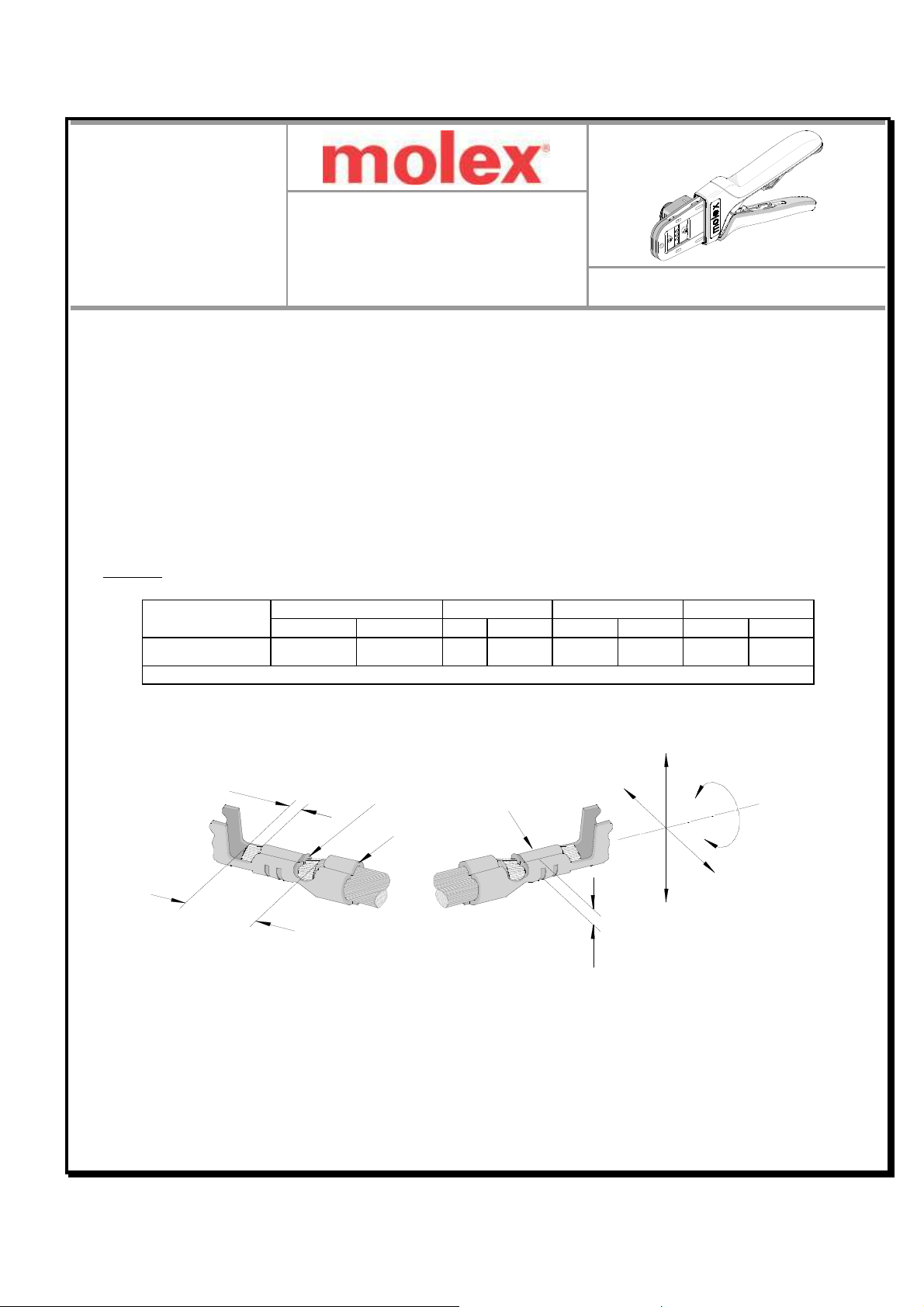
Hand Crimp Tool For 2.00mm (.079”) Pitch CLIK-Mat ™ Wir -to-Board Crimp T rminals
Doc No: ATS-638192800 R l as Dat : 07-08-08 UNCONTROLLED COPY Pag 6 of 7
R vision: B R vision Dat : 01-27-12
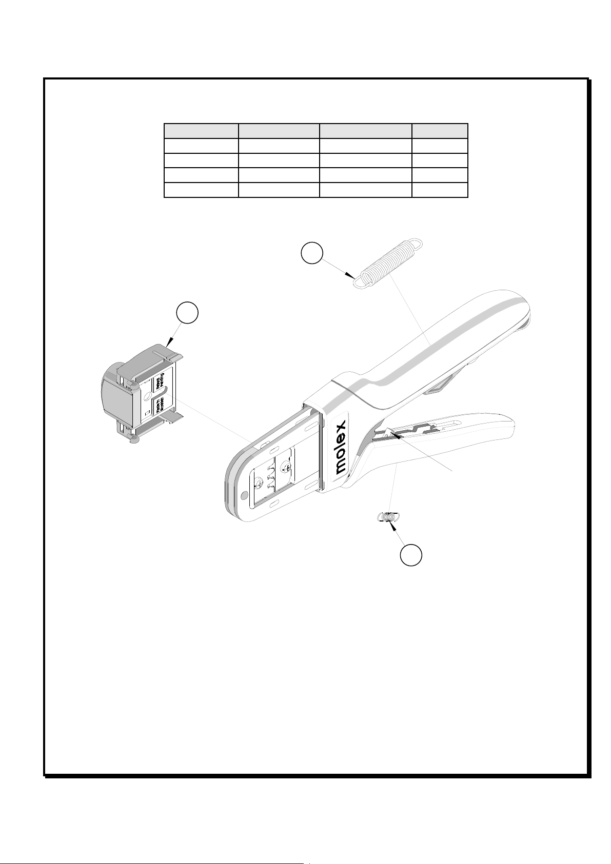
Figure 12
SQUEEZE
THE LINK IN
THE HANDLE
HOLD THE HAND
TOOL IN POSITION
SETTING
WHEEL
RATCHET
RELEASE LEVER
How to Adjust Tool Preload (See
Figure 12)
This hand tool is factory pr s t to 25-45
LBS. pr load. It may b n c ssary ov r
th lif of th tool to adjust tool handl
pr load forc . List d b low ar th st ps
r quir d to adjust th crimping forc of th
hand tool to obtain prop r crimp
conditions:
1. Hold th hand tool in th palm of your
hand as shown in Figur 12. Using
th ind x fing r squ z th link
towards th top of th hand tool fram .
This will r l as th pr load adjustm nt wh l.
2. Rotat th s tting wh l count r-clockwis (CCW) to incr as handl forc . Th numb rs will display high r.
To d cr as handl forc rotat th s tting wh l clockwis (CW).
3. R l as th link to lock th s tting wh l in plac .
4. Ch ck th crimp sp cifications or conduct a pull t st aft r tool handl pr load forc is adjust d.
Warranty
This tool is for l ctrical t rminal crimping purpos s only. This tool is mad of th b st quality mat rials. All vital
compon nts ar long lif t st d. All tools ar warrant d to b fr of manufacturing d f cts for a p riod of 30
days. Should such a d f ct occur, w will r pair or xchang th tool fr of charg . This r pair or xchang will
not b applicabl to alt r d, misus d, or damag d tools. This tool is d sign d for hand us only. Any clamping,
fixturing, or us of handl xt nsions voids this warranty.
CAUTION: Mol x crimp sp cifications ar valid only wh n us d with Mol x t rminals and tooling.
CAUTIONS:
1. Manually pow r d hand tools ar int nd d for low volum or fi ld r pair. This tool is NOT int nd d for
production us . R p titiv us of this tool should b avoid d.
2. Insulat d rubb r handl s ar not prot ction against l ctrical shock.
3. W ar y prot ction at all tim s.
4. Us only th Mol x t rminals sp cifi d for crimping with this tool.
Certification
Mol x do s not c rtify or r -c rtify hand tools but rath r suppli s th following guid lin s for custom rs to r -c rtify
hand tools.
% This tool is qualifi d to pull forc only. S th Mol x w b sit for th Quality Crimp Handbook for mor
information on pull t sting.
% If th tool do s not m t minimum pull forc valu s, handl pr load should b incr as d and th pull t st
r run, (S How to Adjust Pr load).
% Wh n th hand tool is no long r capabl of achi ving minimum pull forc , it should b tak n out of s rvic and
r plac d.