molex AKM-405 User manual

Doc. No.: 638171800 Release Date: 07-20-18 UNCONTROLLED COPY
Revision: C1 Revision Date: 08-09-23
OPERATING INSTRUCTION
AKM - 405
Pneumatic Stripping Machine
Version
03/2022_REV.C
Item-No.
63817-1800
Errors and technical modification subject to change

2 / 19
Operating Instruction
Instruction 1 of 2
Operation
Molex Application Tooling
3 Sammons Court
Bollingbrook, IL 60440
USA
www.molex.com
Date of issue Version
20.07.2018 Rev. A
21.08.2018 Rev. B
21.03.2022 Rev. C
09.08.2023 Rev. C1
Reproduction of these instructions or parts of them in whatever form is not permitted without express
written permission from the publisher. We reserve the right to make technical changes necessary to
improve the machine that could diverge from figures and information in these instructions.

3 / 19
Table of Contents
1. Instruction ....................................................................................................................................4
1.1. Product description................................................................................................................... 4
1.2. Conformity ................................................................................................................................ 4
1.3. Dealing with the operating instruction ....................................................................................... 4
2. Safety...........................................................................................................................................5
2.1. Warning and Safety instructions................................................................................................ 5
2.2. General safety instructions........................................................................................................ 6
2.3. Responsibilities ......................................................................................................................... 6
2.4. Intended use............................................................................................................................. 7
2.5. Predictable misuse ................................................................................................................... 7
2.6. Hazardous area ........................................................................................................................ 8
3. Delivery ........................................................................................................................................8
3.1. Packing .................................................................................................................................... 8
3.2. Scope of delivery ...................................................................................................................... 8
4. Technical description ....................................................................................................................9
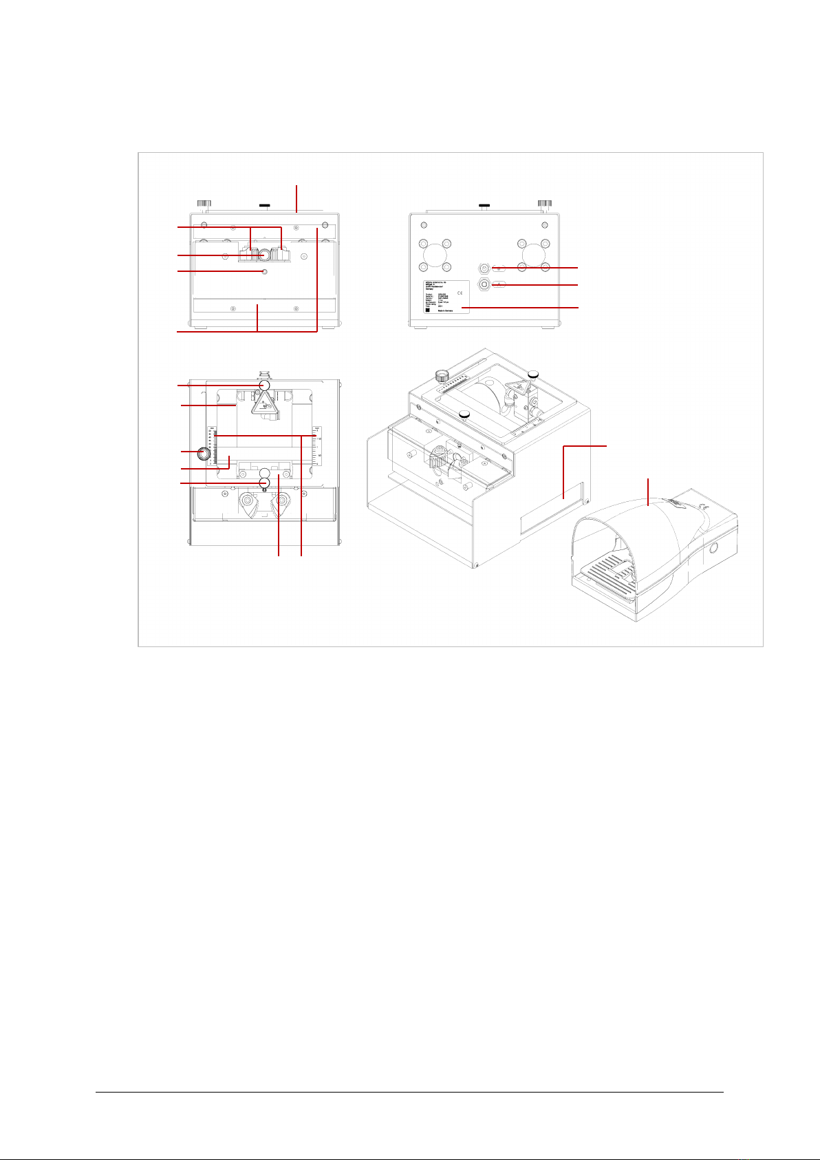
4.1. Machine overview ..................................................................................................................... 9
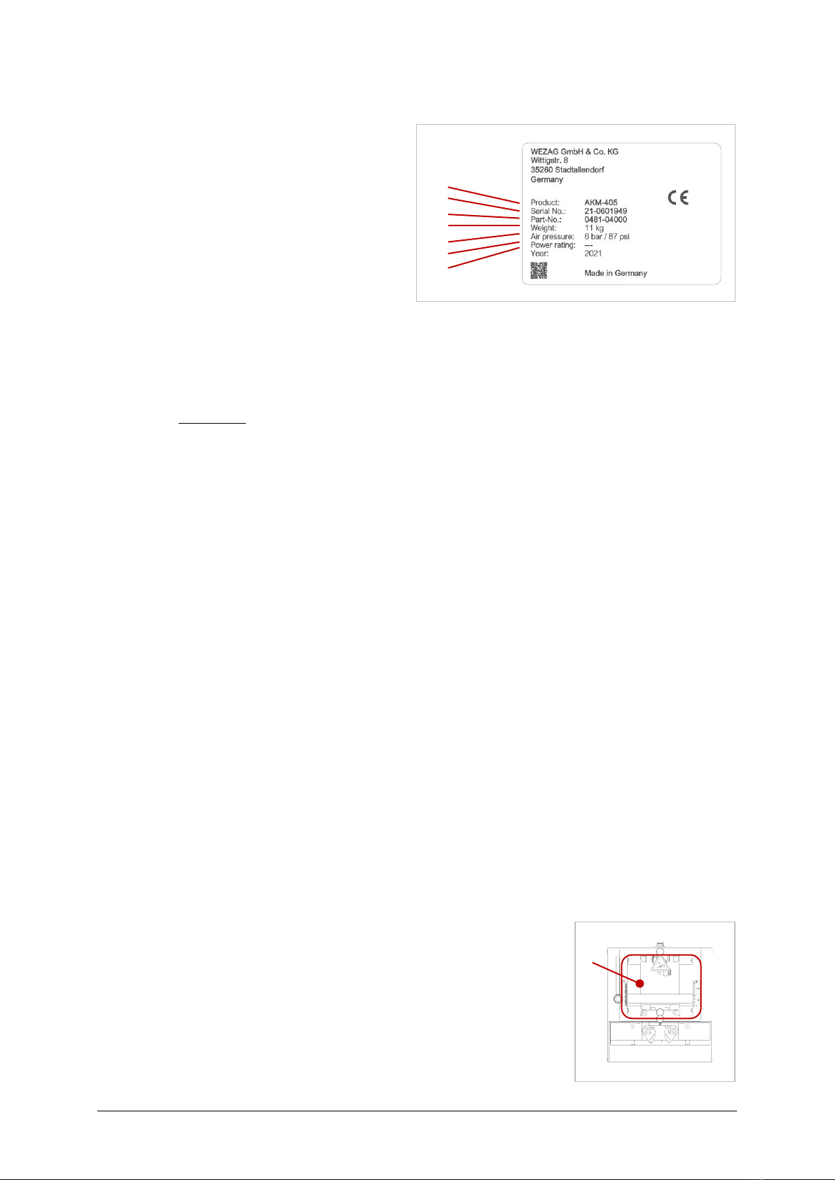
4.2. Machine identification ............................................................................................................. 10
4.3. Technical date ........................................................................................................................ 10
4.4. Functional and operating elements ......................................................................................... 10
4.4.1. Safety cover.................................................................................................................... 10
4.4.2. Stripping length............................................................................................................... 11
4.4.3. Knife opening.................................................................................................................. 11
5. Transport, Storage......................................................................................................................11
5.1. Transport................................................................................................................................ 11
5.2. Storage................................................................................................................................... 11
6. Assembly and Connection ...........................................................................................................12
6.1. Assembly................................................................................................................................ 12
6.2. Connection ............................................................................................................................. 13
7. Setting up / Changeover..............................................................................................................13
7.1. Equipment .............................................................................................................................. 13
7.2. Change centering guide bushes ............................................................................................. 14
7.3. Converting the knife................................................................................................................ 15
8. Production operation...................................................................................................................16
9. Maintenance / Service.................................................................................................................17
9.1. Maintenance plan ................................................................................................................... 17
9.1.1. Daily ............................................................................................................................... 17
9.1.2. Weekly............................................................................................................................ 17
10. Troubleshooting and fault analysis ...........................................................................................18
11. Decommissioning, Dismantling, Disassembly ...........................................................................18
12. Disposal.................................................................................................................................19
13. Accessories overview .............................................................................................................19
14. Repair ...................................................................................................................................... 19

4 / 19
1. Instruction
1.1. Product description
The AKM-405 pneumatic stripping machine is a bench-top universal stripping machine.
A matching centering guide bush and the suitable knife are mounted to match the cable / wire.
The foot switch triggers the stripping process.
1.2. Conformity
The machine is CE compliant.
The original of the following declaration of conformity was supplied together with the operating
instructions of the machine.
1.3. Dealing with the operating instruction
The operating instruction contains all information concerning operating elements, operation,
commissioning, and maintenance work as well as technical data.
The operating instruction must be constantly within reach of the machine.
The producer as well as the distributor decline to accept any liability for damages that are
incurred because the instructions on the machine or in the operation instruction have been
disregarded.
The user is responsible for supplementing the operation instruction with any instructions re-
sulting from current national regulations for accident prevention and protection of the environ-
ment.
The German original version is legally binding.
The operating instructions must be kept for future reference.
Fig. 1.2

5 / 19
2. Safety
2.1. Warning and Safety instructions
The following warnings and safety related cautionary notices in the individual chapters alert
you to various levels of danger:
DANGER indicates a hazard with a high level of risk, which, if not avoided, will result in death
or serious injury.
WARNING indicates a hazard with a medium level of risk, which, if not avoided, may result in
death or serious injury.
CAUTION indicates a hazard with a low level of risk, which, if not avoided, may result in minor
or moderate injury.
If this information is not observed, this may lead to deteriorations in the operating process or
damage to the machine.
Specific dangers are indicated by the following pictograms:
Warning against hand injuries
Warning against cuts
Additional notes are highlighted as follows:
These texts provide additional information and tips.
DANGER
WARNING
CAUTION
ATTENTION
INFO

6 / 19
2.2. General safety instructions
+The national regulations concerning the legal minimum age must be observed when oper-
ating the machine. It is strictly forbidden to allow younger persons access to the machine.
+The employer is responsible for the selection, provision, and use of personal protective
equipment, in compliance with national legislation.
+Everyone who is assigned to work on the machine must have read and understood the
operating instructions. He must observe these operating instructions while carrying out
work on or with the machine.
+Do not operate the machine before you have read and understood all instructions.
+Before each start-up, check that all safety devices and an adapter approved by the manu-
facturer are in place and working properly.
+The machine may only be operated with the specified operating pressure of 6 bar.
+The machine may only be operated with mounted knives approved by the manufacturer.
+The machine may only be set up and operated in a technically perfect condition and in a
safety- and hazard-conscious manner.
+If defects are found on the machine, the work must be interrupted, and the malfunction
must be eliminated before further work is carried out with the machine.
+Only one person may work on or with the machine.
+Only trained personnel may work on the machine.
+When working with the machine, do not wear loose clothing, loose jewelry or long, open
hair, which can get caught in the parts of the machine.
2.3. Responsibilities
The machine may only be operated by suitably trained and authorized personnel.
The user of the machine is responsible for making sure that all persons involved in any way,
either in the installation or in maintenance of the machine, have been thoroughly trained on
the system using this operating instruction.
The user is also responsible for the training of operators and the instruction must include the
following aspects:
+Purpose of the machine
+Hazard zones
+Safety rules and regulations
+Functionality of the various components of the machine
+Proper operation of the machine
To assure full familiarization with the system, the training must be conducted in the native
language of the operators involved.
Staff qualifications required in conjunction with the use of the machine:
Installation
Set-up
Disposal
Instruction
Technical personnel with language proficiency in either English or Ger-
man, in addition to the native language of the operator.
Operation
Qualified persons trained by technical experts.
Maintenance
Service
Repair
Only personal provided or trained by the manufacturer.
The safety instructions, warnings and precautions contained in the individual chapters must
be strictly observed by all users and operators!

7 / 19
2.4. Intended use
The machine is designed for stripping cables and wires.
The maximum cross-section to be processed depends on the respective material.
The following guide values serve for standard applications:
+Ø 4 - 15 mm (Ø 0,16 –0,6 inch) resp. 6 - 70 mm²; AWG 9 –AWG 2/0
2.5. Predictable misuse
The manufacturer or distributor is not liable for damage resulting from improper use: the risk
for this is borne solely by the user.
Examples of predictable misuse:
+Processing of round material of steel, aluminum or wood.
+Using wires with the wrong knife insert.
+Using wires with the wrong centering guide bush.
+Use of not approved knives for the machine.
+Using the machine to press in parts.
+Using the machine for embossing.

8 / 19
2.6. Hazardous area
Risk of cutting and crushing fingers and hands.
Always operate the machine with the safety cover.
There is a risk of cutting and crushing fingers and
hands. Never bridge the query switch of the safety
cover. Always operate the machine with the safety
cover mounted.
Never reach into the cutting edges when changing
the knives.
3. Delivery
3.1. Packing
Retain the original packaging for later shipping and storage of
the machine.
Dimension:
Length: 560 mm (22,05 inch)
Width: 350 mm (13,8 inch)
Height: 350 mm (13,8 inch)
Total Weight: approx. 23 kg (50,7 lbs)
(wooden box + machine)
3.2. Scope of delivery
1 pc. Pneumatic stripping machine AKM-405
1 pc. Foot switch with protective cover
1 pc. Knife set (3-fold à 4 cutting edges; Ø 4 –15 mm)
1 pc. Centering guide bush set Ø 6, 8, 10, 12, 14,16mm.
2 pcs. PU compressed air hose Ø 8 mm à 2 Meter (without quick coupling)
1 pc. PU compressed air hose Ø 6 mm à 2 Meter
1 pc. Operating instruction
1 pc. Declaration of Conformity
WARNING
Fig. 2.6.1
Fig. 3.1

9 / 19
4. Technical description
4.1. Machine overview
Pos.
Designation
Pos.
Designation
01
Pneumatic stripping machine AKM-405
09
Stop f. stripping length
02
Cable clamps
10
Stripping length indicator mm + inch
03
Centering guide bush
11
Knife block
04
Adjusting screw f. knife opening
12
Ø 6 / B = control pressure
05
Intervention guard top + down
13
Ø 8 / A = control pressure
06
Safety cover
14
Nameplate
07
Knurled screws f. safety cover
15
Tray f. insulation waste
08
Knurled screw f. stripping length
16
Foot switch with protective cover
Fig. 4.1
07
06
08
09
07
12
13
14
02
03
04
05
01
15
16
11 10

10 / 19
4.2. Machine identification
Pos. Designation
1Machine type
2Serial number
3Item number
4Weight
5Operating air pressure
6Eletrical connection
7Year of manufacture
4.3. Technical date
Dimension:
Lenght: 265 mm (10,43 inch)
Width: 235 mm (9,25 inch)
Height: 200 mm (7,87 inch)
Weight: approx. 11 kg (24,25 lbs)
Operating air pressure: 6 bar / 87 psi
Air consumption: 4,2 L
Cable cross-section: Ø 4 –15 mm (Ø 0,16 –0,6 inch)
resp. 6 –70 mm² (AWG 9 –2/0)
Insulation diameter: max. Ø 16 mm (Ø 0,63 inch)
Stripping length: 5 –50 mm (0,2 –2 inch)
Emission noise level LpA: < 79 dB
4.4. Functional and operating elements
4.4.1. Safety cover
The machine is equipped with a safety cover. This is designed
to cover the moving parts of the machine.
The safety cover is interrogated by pressing a pneumatic button.
The machine cannot be operated when the safety cover is re-
moved.
1
2
3
4
5
6
7
Fig. 4.2
Fig. 4.4.1

11 / 19
4.4.2. Stripping length
The stop of the stripping length is set to the desired length with a
knurled screw.
+Loosen the knurled screw.
+The stop can be set to the desired length by sliding the screw.
The length can be read on the right (inch) and left (mm).
+Retighten the knurled screw.
4.4.3. Knife opening
The knife opening is adjusted to the cable outer diameter using
a 4 mm hexagonal pin wrench (not included).
Larger opening: turn clockwise.
Smaller opening: turn counterclockwise.
5. Transport, Storage
5.1. Transport
Danger of crushing if the machine falls down.
Wear suitable safety shoes when transporting and setting up the machine.
5.2. Storage
Corrosion of the machine due to incorrect storage.
Store the machine and accessories at 5 - 55 °C and max. 90 % relative humidity (non-
condensing) in the original packaging.
WARNING
ATTENTION
Fig. 4.4.2
Fig. 4.4.3

12 / 19
6. Assembly and Connection
Risk of injury
In the event of defects or damage to the machine, it must be shut down immediately and
secured against unintentional or unauthorized startup. The machine may only be put into op-
eration if it is in perfect technical condition.
6.1. Assembly
Danger of crushing due to the machine falling down / over.
Wear suitable safety shoes when transporting and setting up the machine.
Set up the machine on a level surface and ensure that the machine is stable.
Slip, trip and fall due to incorrectly routed cables.
Place the foot switch on the floor, any other placement of the foot switch than on the floor is
prohibited!
Do not lay the foot switch and cables in traffic routes!
Disturbance of the musculoskeletal system due to insufficient access to the control parts.
The access to the actuating parts of the machine must be kept free. This applies in particular
to the foot switch.
To reduce the operating noise, you can place the machine on a non-slip rubber base.
WARNING
WARNING
CAUTION
CAUTION
INFO
Fig. 6.1.1
Fig. 6.1.2

13 / 19
6.2. Connection
Seizure of the compressed air hose due to non-observance of the connection sequence.
Observe the connection sequence. The machine can only be completely depressurized via
the quick coupling (not included in the scope of delivery) on the main air supply line.
Malfunction
Operate the machine only with clean, dry and oil-free compressed air.
Operating pressure: 6 bar (pressure gauge not included).
1. 2. 3.
Connection 2 B Connection 1 foot switch
Connection 4 A
7. Setting up / Changeover
Risk of cutting and crushing due to unintentional start-up caused by human error.
Before starting setup and changeover work, the machine must be safely disconnected from
the energy supply.
Malfunctions due to mounting errors.
Mounting errors can lead to damage during operation.
Check the correct combination of centering guide bush and knife. The knife edges must match
each other.
7.1. Equipment
Centering guide bush set Knives set
Item-No.: 1881-04021 / 63817-1803 Item-No.: 1881-04022 / 63817-1804
WARNING
ATTENTION
WARNING
ATTENTION
Fig. 7.1.1
Fig. 7.1.2
Ø 8

14 / 19
7.2. Change centering guide bushes
1. 2. 3.
4. 5. 6.
Loosen
7. 8. 9.
Fix lightly
SW 4
SW 2,5

15 / 19
7.3. Converting the knife
Risk of cutting fingers in the knife area.
Do not insert your fingers into the knife edge. Follow the operating instructions exactly when
changing the knife.
1. 2. 3.
4. 5. 6.
Loosen
7. 8. 9.
Adjust
The knives can be adjusted by 0.5 mm towards the center by screwing in the screws on the
side for each side of the knife.
WARNING
INFO
SW 4
SW 4
SW 1,5

16 / 19
8. Production operation
Discomfort caused by the stripping process towards the operator.
Keep as large a distance as possible in front of the machine.
1. 2. 3.
4 5. 6.
7. 8.
CAUTION

17 / 19
9. Maintenance / Service
9.1. Maintenance plan
Risk of crushing due to unintentional start-up caused by human error.
Before starting maintenance and servicing work, the machine must be safely disconnected
from the power supply.
To ensure a long service life and optimum use, the following maintenance and lubrication spec-
ifications must be observed. The manufacturer accepts no liability for damage caused by ne-
glect of the specified maintenance and lubrication specifications.
Regular cleaning and maintenance of the parts accessible from the outside maintains the op-
erational readiness of the machine.
The machine or machine parts must not be cleaned with:
+compressed air,
+hard objects such as spatula, steel wool or similar,
+fibrous materials such as cleaning wool or similar.
Vacuum coarse dirt and abrasion.
9.1.1. Daily
Malfunction due to wrong cleaning.
Do not blow out insulation and cable residues with compressed air, otherwise the smallest
residues will be blown into the machine housing. This increases wear and tear and impairs
accuracy and function.
+External visual inspection of the machine.
+The machine's connection hoses must be checked regularly. Defective hoses must be re-
placed immediately.
+Check compressed air (6 bar) at house unit (pressure gauge not included in the scope of
delivery).
+Remove insulation and cable residues in the machine.
9.1.2. Weekly
Danger of cutting fingers in the knife area.
Do not put your hands into the knife edge. Follow the operating instructions exactly when
changing the knife.
Maintenance work may only be carried out by authorized persons who have been trained for
this activity.
+Check cut material for a clean cut.
+Check knife for damage and wear.
WARNING
ATTENTION
WARNING

18 / 19
10. Troubleshooting and fault analysis
Risk of injury
If defects or damage to the machine are detected, it must be shut down immediately and
secured against unintentional or unauthorized startup.
Faults and malfunctions may only be rectified by authorized persons who have been trained
for this activity.
Error / Fault
Remedy and Explanation
Poor cutting quality
Worn knives
Replace new knife or complete knife
set.
Knives badly
adjusted
Realign knife.
In case of problems, the customer service is at your disposal. The service address can be
found on page 2 of these operating instructions.
Please have all necessary information ready for the conversation, including:
+Machine type
+Serial number of the machine
+Photos / Videos
11. Decommissioning, Dismantling, Disassembly
Danger of crushing if the machine falls down.
Wear suitable safety shoes when transporting and dismantling the machine.
Seizure of the compressed air hose due to incorrect connection.
Observe the disconnection sequence.
The machine is to be completely depressurized only through the main air supply line.
Corrosion of the machine due to incorrect storage.
Store the machine and accessories at 5 - 55 °C and max. 90 % relative humidity (non-
condensing) in the original packaging.
1. 2.
WARNING
WARNING
WARNING
ATTENTION

19 / 19
12. Disposal
Environmental hazard
Operating fluids that are not disposed of properly can cause short- and long-term environmen-
tal damage!
Skin irritations due to contact with greases or oils.
Wear suitable protective gloves and glasses as well as safety shoes. Observe the safety in-
structions in the "Safety data sheet" of the grease or oil.
It is the responsibility of the machine operator to ensure that the machine and its operating
materials are disposed of in an environmentally compatible and professional manner. In doing
so, observe the national and local legal requirements and regulations.
The machine is disposed of as follows:
1. Properly decommission the machine.
2. Disassemble the machine.
3. Drain off operating materials (oils, greases, etc.) or remove them from the machine com-
ponents and have them disposed of in an environmentally compatible form by a specialist
company.
4. Sort materials by category and take each material category to a suitable recycling point.
13. Accessories overview
Foot switch Order-No.: 1481-04023 / 63817-1807
Connection hose set Order-No.: 1881-01021 / 63817-1806
Centering guide bush set Order-No.: 1881-04021 / 63817-1803
Knives set Order-No.: 1881-04022 / 63817-1804
14. Repair
Repairs to the machine may only be carried out by the manufacturer himself or by qualified
personnel trained by him. Only original spare parts from the manufacturer may be used.
If the machine is sent to the manufacturer for repair, the following points must be observed:
+The machine must be sent in the original packaging.
+All parts necessary for operation and function must be returned.
+Additional accessories as well as processing sample material must be enclosed.
WARNING
CAUTION
Table of contents
Other molex Industrial Equipment manuals