molex FA2 Operating instructions

FA2 Applicator
Doc. No: TM-638080200 Release Date: 02-08-18 UNCONTROLLED COPY Page 1 of 33
Revision: B2 Revision Date: 05-04-18
FA2 CRIMP APPLICATOR
General Description, Setup and Operating Instructions
Document No. 63808-0200
Start-Up Guide
Page 10

FA2 Applicator
Doc. No: TM-638080200 Release Date: 02-08-18 UNCONTROLLED COPY Page 2 of 33
Revision: B2 Revision Date: 05-04-18

FA2 Applicator
Doc. No: TM-638080200 Release Date: 02-08-18 UNCONTROLLED COPY Page 3 of 33
Revision: B2 Revision Date: 05-04-18
Safety Warnings and Information
Read and understand all instructions and safety information in this manual before
operating or servicing this tool.
Keep this manual available when using this tool.
Replacement manuals are available for download at www.molex.com.
SAFETY ALERT SYMBOL
This symbol is used to call your attention to hazards or unsafe practices that could result in an injury or property damage.
The signal word, defined below, indicates severity of hazard. The message following the signal word provides information for
prevention or avoidance of the hazard.
DANGER
DANGER:
Indicates an imminently hazardous situation that, if not avoided, could result in death or serious
injury
WARNING
WARNING:
Indicates a potentially hazardous situation that, if not avoided, could result in death or serious
injury
CAUTION
CAUTION:
Indicates a potentially hazardous situation that, if not avoided, may result in minor or moderate
injury
May also be used to alert against unsafe practices associated with events that could lead to
personal injury
DANGER
Never install or service this machine while connected to any electrical power source. Disconnect power by
unplugging the press from its power source.
Failure to observe this warning could result in severe injury or death.
WARNING
Never operate a press or wire processing machine without guards or safety devices that are intended to
prevent hands from remaining in the die space.
Failure to observe this warning could result in severe injury or death.
WARNING
Never wear clothing or jewelery that is loose or that could potentially hang into the equipement and get
caught.
Failure to observe this warning could result in severe injury or death.
WARNING
Always wear proper eye protection when operating or servicing this equipment.
Failure to wear eye protection could result in serious eye injury from flying debris.

FA2 Applicator
Doc. No: TM-638080200 Release Date: 02-08-18 UNCONTROLLED COPY Page 4 of 33
Revision: B2 Revision Date: 05-04-18
CAUTION
CAUTION
Do not use compressed air to clean this
equipment. The forces created by
compressed air can force debris into the
tool.
Failure to observe these precautions may
result in injury or property damage.
Always hand-cycle the applicator in the
equipment to ensure tooling is properly aligned.
Failure to observe these precautions may result
in injury or property damage.
CAUTION
CAUTION
Heavy Object
To avoid muscle strain or back injury, use
lifting aids and proper lifting techniques when
removing or replacing.
Failure to observe these precautions may
result in injury or property damage.
Never operate, service, install or adjust this
machine without proper instruction and without
first reading and understanding the instructions
in this manual and all applicable press or wire
processing machine manuals.
CAUTION
Always wear proper ear protection when operating or servicing this applicator.
CAUTION
Molex applicators are designed to operate in presses with standard shut heights of 135.80mm (5.346”).
Installation of crimp presses with other-than-standard shut heights can cause tool breakage. It is advisable to
perform a check of the shut height before installation. Molex will not be liable for any damages as a result of
applicator installation in a crimp press with an incorrectly set shut height.
Failure to observe these precautions may result in injury or property damage.
CAUTION
Never perform any service or maintenance other than as described in this manual.
Never modify, alter or misuse the equipment.
Molex crimp specifications are valid only when used with Molex terminals, applicators and tooling.
Failure to observe this precaution may result in injury and property damage.

FA2 Applicator
Doc. No: TM-638080200 Release Date: 02-08-18 UNCONTROLLED COPY Page 5 of 33
Revision: B2 Revision Date: 05-04-18
Table of Contents
Safety Warnings and Information ..................................................................................................................................3
Section 1 –General Description....................................................................................................................................6
1.1 Description.................................................................................................................................................6
1.2 Features ....................................................................................................................................................6
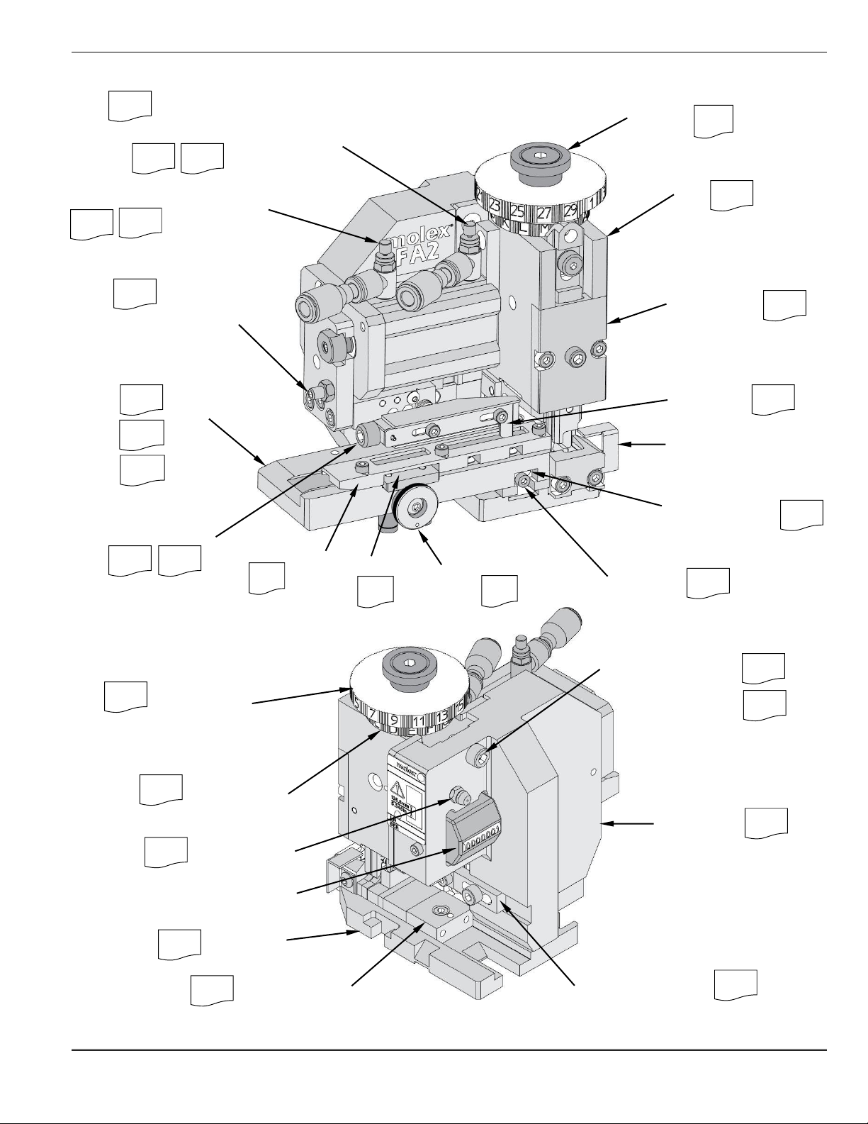
1.3 General Applicator Parts Identification (Mechanical Feed)........................................................................7
1.4 General Applicator Parts Identification (Air Feed)......................................................................................8
1.5 Applicator Tooling Identification.................................................................................................................9
Section 2 –Start-Up Guide..........................................................................................................................................10
Section 3 –Troubleshooting........................................................................................................................................12
3.1 Applicator Troubleshooting......................................................................................................................12
3.2 Crimp Troubleshooting ............................................................................................................................12
Section 4 –Setup and Operation.................................................................................................................................14
4.0 Press Shut Height....................................................................................................................................14
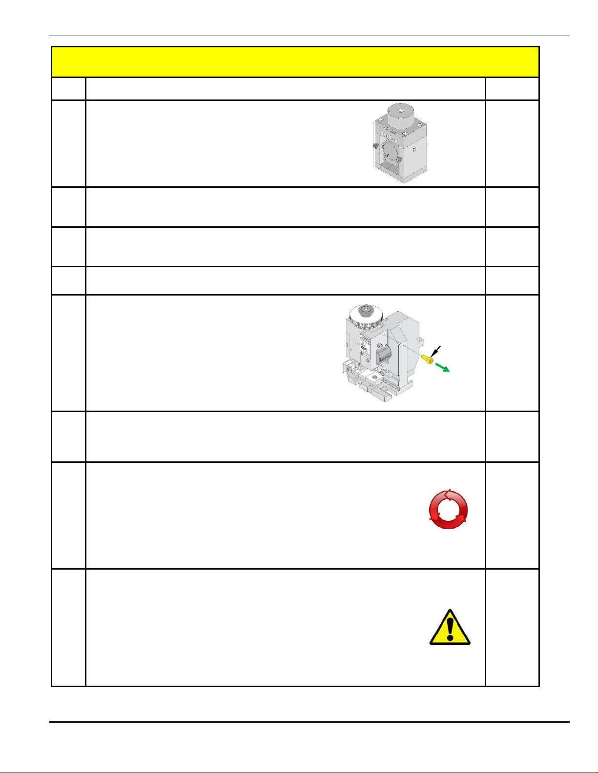
4.1 Applicator Installation and Removal ........................................................................................................14
4.2 How to Make a Crimp ..............................................................................................................................15
4.3 Crimp Height Adjustments.......................................................................................................................15
4.4 Track Guide Setup and Adjustment.........................................................................................................16
4.5 Loading and Unloading Terminals in the Applicator Track.......................................................................18
4.6 Terminal Feed Adjustments.....................................................................................................................19
4.7 Terminal Track Position Adjustment ........................................................................................................22
4.8 Crimp Tooling Installation and Removal ..................................................................................................23
4.9 Wire Stop Setup and Adjustment.............................................................................................................25
4.10 Wire Processing Setup and Feed Cam Orientation .................................................................................27
4.11 Bend Adjust Dial......................................................................................................................................28
Section 5 –Maintenance .............................................................................................................................................29
5.1 Cleaning ..................................................................................................................................................29
5.2 Lubrication...............................................................................................................................................29
5.3 Storage....................................................................................................................................................29
Section 6 –Service Parts ............................................................................................................................................30
6.1 Feed Pawl Spring Replacement ..............................................................................................................31
6.2 Accessories .............................................................................................................................................32
6.3 Contact Us...............................................................................................................................................32
Section 7 –Crimp Quality............................................................................................................................................33

FA2 Applicator
Doc. No: TM-638080200 Release Date: 02-08-18 UNCONTROLLED COPY Page 6 of 33
Revision: B2 Revision Date: 05-04-18
Section 1 –General Description
1.1 Description
The FA2 applicator fits in the Molex TM-2000, TM-3000 and TM-4000 Universal Presses and in most industry-standard crimp
presses with 135.8mm (5.346”) shut height and 3-point base plate mounting to the press bolster.
Molex currently offers the following crimp presses for operating the FA2 applicator:
Description
Order Number
TM-3000 Press 120 V 50/60 Hz
63801-7200
TM-3000 Press 240 V 50/60 Hz
63801-7300
TM-4000 Press 240 V 50/60 Hz
63801-7600
1.2 Features
Fine adjustment allows users to achieve target with little effort by adjusting in increments of 0.015mm (.0006”) for
conductor crimp height and in increments of .025mm (.001”) for insulation crimp height.
Independent adjustment cams allow users to quickly adjust conductor or insulation crimp height without affecting each
other.
The track position for bellmouth and cut-off tab can be adjusted while the applicator is in the press.
This applicator does NOT fit in the Molex TM-40 or TM-42 presses.
Directly adapts to most automatic wire processing machines.
Compatible with 30mm and 40mm stroke presses; no changes necessary in applicator.
Quick setup time; crimp heights, track position, and feed adjustments can be adjusted while the applicator is in the press.
This applicator is designed to industry-standard 3-point mounting and 135.80mm (5.346”) shut height.
Press Stroke Compatibility
28.6mm (1 1/8”) minimum
41.3mm (1 5/8”) maximum
Applicator Mounting in Press
oThis applicator uses the industry-standard 3-point base plate mounting to the press bolster and T-shape industry-
standard ram mounting.
Guarding
This applicator is supplied without guards and is intended to be used with guards supplied by the press manufacturer.
Caution: DO NOT operate the applicator without guards.

FA2 Applicator
Doc. No: TM-638080200 Release Date: 02-08-18 UNCONTROLLED COPY Page 7 of 33
Revision: B2 Revision Date: 05-04-18
1.3 General Applicator Parts Identification (Mechanical Feed)
Indicates manual page number for more information
LUG BOLT
FEED CAM
RAM
POSITION
ADJUSTING KNOB
PUNCH COVER
14
27
23
20
17
TRACK
23
19
18
22
19
FEED PAWL
SCRAP CHUTE
TERMINAL GUIDE
TRACK
LOCKING SCREW
22
17
18
TRACK ADJUSTING
SCREW
22
DRAG BRAKE KNOB
18
DRAG BRAKE
29
16
RAM STORAGE SCREW
INSULATION
ADJUSTING CAM
15
14
15
CONDUCTOR
ADJUSTING CAM
29
GREASE FITTING
* CYCLE COUNTER
(NON-RESETTABLE)
25
WIRE STOP ASSEMBLY
BACK FRAME
16
MOUNTING DATUM
24
BASE PLATE
*Depending on conditions during applicator assembly and setup, the counter reading may vary on new applicators.

FA2 Applicator
Doc. No: TM-638080200 Release Date: 02-08-18 UNCONTROLLED COPY Page 8 of 33
Revision: B2 Revision Date: 05-04-18
1.4 General Applicator Parts Identification (Air Feed)
14
RAM STORAGE SCREW
15
INSULATION
ADJUSTING CAM
15
CONDUCTOR
ADJUSTING CAM
29
29
16
25
WIRE STOP ASSEMBLY
BACK FRAME
16
9
24
MOUNTING DATUM
GREASE FITTING
*CYCLE COUNTER
(NON-RESETTABLE)
BASE PLATE
Indicates manual page number for more information
LUG BOLT
PUNCH COVER
14
SPEED CONTROL
(FORWARD STROKE)
20
23
SPEED CONTROL
(BACK STROKE)
21
20
ADJUSTING SCREW
(BACK STROKE)
15
15
23
17
TRACK
FEED PAWL
20
18
POSITION
ADJUSTING KNOB
22
RAM
SCRAP CHUTE
TERMINAL GUIDE
DRAG BRAKE KNOB
22
18
17
19
20
22
TRACK ADJUSTING
SCREW
TRACK
LOCKING SCREW
DRAG BRAKE
18
* Depending on conditions during applicator assembly and setup, the counter reading may vary on new applicators.

FA2 Applicator
Doc. No: TM-638080200 Release Date: 02-08-18 UNCONTROLLED COPY Page 9 of 33
Revision: B2 Revision Date: 05-04-18
1.5 Applicator Tooling Identification
Note: The above is a generic illustration. Please refer to the Application Tooling Specification (ATS) document
for your specific applicator to identify replacement parts and part numbers.
Tooling component used on some applicators
CONDUCTOR PUNCH
INSULATION PUNCH
FEED CAM
(NOT USED ON
AIR FEED APPLICATORS)
TERMINAL HOLD DOWN
CONDUCTOR STUFFER
BLADE AND SPRING
INSULATION STUFFER
AND SPRING
FRONT PLUNGER
STRIKER
TERMINAL GUIDE
COARSE/FINE
SPACERS
HEIGHT SPACER
CONDUCTOR ANVIL
FRONT PLUNGER
RETAINER
PUNCH
COVER
SCRAP
CHUTE
FRONT CUT-OFF
PLUNGER AND
SPRING
INSULATION ANVIL

FA2 Applicator
Doc. No: TM-638080200 Release Date: 02-08-18 UNCONTROLLED COPY Page 10 of 33
Revision: B2 Revision Date: 05-04-18
Section 2 –Start-Up Guide
Step
Instruction
Page
1
Verify Press Compatibility
oPress stroke is between 26.8-41.2mm (1 1/8-1 5/8”)
oPress shut height is 135.8mm (5.346”)
o3-point universal base plate mounting
oT-shape universal ram mounting
5, 12
2
Confirm Terminal, Wire and Tool
Use the applicator’s ATS document to confirm the applicator is compatible with Molex terminal part number
and selected wire (conductor size and insulation diameter).
ATS
3
Set Up Applicator for Wire Processing (If Applicable)
oAs shipped, Molex applicators are set up for bench crimping.
oFor wire processing applications, please review section 4.10.
25
Test Fit Terminal Strip in the Track
oMake adjustments to the guide cover if terminals are too tight or loose.
4
Install Applicator in Press
oRemove ram storage screw.
oInstall the applicator into the press and engage the lock.
oConnect the air lines (air feed applicators only) to the air valve.
12-13
5
Install Terminal Reel and Load Terminals in Track
oTerminal strip must slide freely in track without excessive play.
oCenter the first terminal above the anvils.
oMake sure the drag brake is ON before operating the press.
16-20
6
Hand-Cycle/Slow-Cycle the Press
oRecord the insulation adjusting cam and conductor adjusting cam factory settings.
oTo prevent tool damage, move the insulation adjusting cam to setting 1and the
conductor adjusting cam to setting A.
oVerify back feed pawl position engages the terminal strip carrier hole.
oStop the press if there is any tightness or binding.
oStop the hand-cycle/slow-cycle when the press ram is at the top of its stroke.
oVerify the forward feed position (terminal centered over anvils).
oHand-cycle/slow-cycle several times to crimp terminals and evaluate the feed and cut-off tab.
13-14,
18-19
7
Crimp with Wire (Production Speed)
oVerify that terminals feed properly before crimping under power.
oClose the guards and turn on press power.
oCrimp a pre-stripped wire and evaluate. Crimps will be loose because the insulation
adjusting cam and conductor adjusting cam are at their loosest settings.
oMove the insulation adjusting cam and conductor adjusting cam halfway to the factory
settings and crimp again.
oBegin measuring the crimp heights and compare to ATS specifications.
oIncrementally increase the insulation adjusting cam and conductor adjusting cam settings over several
crimps until ATS crimp specifications are met.
13-14,
17-19
RAM STORAGE
SCREW

FA2 Applicator
Doc. No: TM-638080200 Release Date: 02-08-18 UNCONTROLLED COPY Page 11 of 33
Revision: B2 Revision Date: 05-04-18
Visual Inspection of Crimped Terminals
Application Tooling Support
Phone: (402) 458-TOOL (8665)
E-Mail: [email protected]
Website: www.molex.com/applicationtooling
8
Inspection
oMeasure crimp characteristics as specified in the ATS and adjust accordingly.
ATS
9
Ready for Production
Examples
Improper Wire Preparation
Optimal Crimp
Measurement of Crimp Height
Note: Do not measure extrusions.

FA2 Applicator
Doc. No: TM-638080200 Release Date: 02-08-18 UNCONTROLLED COPY Page 12 of 33
Revision: B2 Revision Date: 05-04-18
Section 3 –Troubleshooting
3.1 Applicator Troubleshooting
Note: ATS refers to the Application Tooling Specification document for the applicator.
Symptom
Cause
Solution
See Page
Terminals not feeding
or inconsistent feed
Terminal strip bent or damaged
Replace terminals
—
Terminal strip pulled tight from reel
Terminals should be loose loop from the reel
21
Feed pawl not properly adjusted
Check proper pawl setting
17
Tip of feed pawl worn
Replace feed pawl
—
Drag brake not on
Rotate drag brake knob (dot down)
18-19
Feed pawl not moving back enough to pick up the
terminal (pitch)
Mechanical feed applicator: Verify correct feed
cam installed
ATS
Air feed applicator: Adjust back stroke
21
Terminal jammed under terminal guide
Clear and reinsert terminals
18
Feed pawl guide not aligned to terminal strip’s
carrier holes
Readjust feed pawl guide
17
Terminal guide adjusted too tight
Readjust terminal guide
17-18
Track adjusted too far out (terminal insulation grips
rubbing on cut-off plunger)
Adjust track in (away from operator) for proper
cut-off tab and bellmouth size
22
Cut-off plunger stuck
down
Plunger retainer screws overtightened
Loosen screws and re-tighten
—
Cut-off plunger spring fatigued or broken
Replace spring per specification sheet
ATS
Debris buildup in plunger area
Disassemble and clean
—
Carrier strip jammed in cut-off plunger
Cut out damaged terminal strip and feed in
clean strip
—
Cutting edges worn or damaged (cut-off plunger,
retainer or insulation anvil)
Remove scoring marks and if problem not
solved, replace the worn cut-off plunger, cut-off
retainer or insulation anvil
ATS
3.2 Crimp Troubleshooting
Symptom
Cause
Solution
See Page
Crimp bellmouth too
large or cut-off tab
too small
Wrong crimp tooling
Replace per specification sheet
ATS
Wrong terminal
Replace per specification sheet
ATS
Worn or damaged tooling
Replace per specification sheet
ATS
Track adjusted too far out (toward operator)
Adjust track in (away from operator) to reduce
bellmouth or increase the cut-off tab
22
Crimp bellmouth too
small or cut-off tab
too large
Track adjusted too far in (away from operator)
Adjust track out (toward the operator) to
increase bellmouth or cut-off tab
22
Wrong crimp tooling
Replace per specification sheet
ATS
Conductor crimp too
loose (per
specification)
Wrong crimp tooling
Replace per specification sheet
ATS
Worn or damaged tooling
Replace per specification sheet
ATS
Wrong conductor cam setting
Measure crimp height and adjust accordingly
15-16
Press shut height too high (loose)
Calibrate press shut height to 135.8mm
14
Conductor crimp too
tight (per
specification)
Wrong crimp tooling
Replace per specification sheet
ATS
Wrong conductor cam setting
Measure crimp height and adjust accordingly
15-16
Press shut height is too low (tight)
Calibrate press shut height to 135.8mm
14

FA2 Applicator
Doc. No: TM-638080200 Release Date: 02-08-18 UNCONTROLLED COPY Page 13 of 33
Revision: B2 Revision Date: 05-04-18
Symptom
Cause
Solution
See Page
Insulation crimp too
loose (poor strain
relief)
Wire insulation diameter too small
Verify insulation diameter is within
specification
ATS
Wrong insulation cam setting
Adjust insulation cam for tighter crimp
15-16
Worn or damaged tooling
Replace tooling if necessary
ATS
Insulation crimp too
tight (damaging
insulation)
Wire insulation diameter too large
Verify insulation diameter is within
specification
ATS
Wrong insulation cam setting
Adjust insulation cam for looser crimp
15-16
Wrong insulation crimp tooling
Replace with correct tooling
ATS
Press shut height is too low
Calibrate press shut height to 135.8mm
14
Terminal sticks in
crimp punches after
crimping
Conductor and/or insulation cam setting causing
over-crimping
Measure crimp height and adjust cams
accordingly
15-16
Incorrect crimp tooling or wire conductor size
Replace with correct tooling or conductor size
per specification sheet
ATS
Wire stop missing or not adjusted
Review specification sheet for missing
components
ATS
Crimp tooling worn or damaged
Replace per specification sheet
ATS
Wire insulation too large for tooling
Loosen insulation crimp cam to 1to test;
review the insulation diameter specification
ATS
Gold plating (including selective plating) or some
high-tensile materials
Install a terminal oiler and potentially replace
tooling
23-24
Terminal nose bend
up or bend down
after crimping
Terminal sticking in crimp punches
(See above troubleshooting)
—
Terminal track adjusted too far in or out
Adjust track for correct bellmouth and cut-off
tab
22
Terminal nose hold down misadjusted or missing
Refer to specification sheet if applicable
ATS
Wire brush length is
inconsistent
Wire stop out of adjustment
Adjust accordingly
23-24
Wire stop missing
Replace per specification sheet
ATS
Wire stripping inconsistent
See strip length range on specification sheet
ATS
Wire is being inserted into the terminal instead of
being put against the wire stop
Touch end of stripped wire to the face of the
wire stop assembly target
—
Operator applying inconsistent force against wire
stop assembly target with the end of the stripped
wire to the face of the wire stop assembly target
Adjust method of presenting the end of the
stripped wire to the wire stop assembly target
—
Excessive crimp
extrusion (flash)
Terminal is over-crimped
See above (Conductor crimp too tight)
15-16
Conductor too big for terminal
Verify conductor size per specification sheet
ATS
Crimp tooling worn or damaged
Replace tooling per specification sheet
ATS
Gold plating or some high-tensile materials
Install a terminal oiler and potentially replace
the tooling
—
Wrong crimp tooling (punch and anvil)
Verify tooling per specification sheet
ATS

FA2 Applicator
Doc. No: TM-638080200 Release Date: 02-08-18 UNCONTROLLED COPY Page 14 of 33
Revision: B2 Revision Date: 05-04-18
Section 4 –Setup and Operation
4.0 Press Shut Height
This applicator must be installed in a crimp press with a standard 135.80mm (5.346”) press shut height.
Shut height should be verified with a calibrated shut height gauge.
Molex offers a shut height gauge (Order No. 63800-7900).
4.1 Applicator Installation and Removal
1. Disconnect power to the press.
2. Clean the bottom of the applicator base plate and the top of the press
bolster of scrap or chips that may interfere with flat applicator installation.
3. Remove the ram storage screw from the back of the applicator
frame.
4. Fit the applicator lug bolt into the press yoke, and align the base
plate notches to the press locking mechanism.
5. Clamp the applicator in the press.
Remove the applicator by reversing the previous steps. For applicator storage instructions, see Section 5.3.
BASE PLATE
RAM STORAGE
SCREW
PRESS YOKE
PRESS LOCKING
MECHANISM

FA2 Applicator
Doc. No: TM-638080200 Release Date: 02-08-18 UNCONTROLLED COPY Page 15 of 33
Revision: B2 Revision Date: 05-04-18
Pneumatic Connection (Air Feed)
1. The air feed applicator uses a double-acting air cylinder that must be actuated by a 4-way air valve.
2. The air cylinder is equipped with push-in fittings for 6mm diameter vinyl or Nylon tube. Adapters are included for ¼”
diameter and 4mm diameter vinyl or Nylon tube.
3. Pneumatic tubes must be connected as shown in Figure 4.1.1.
Tubes are typically connected so the terminal feed is forward
when the applicator ram is up.
4. When using the TM-3000 or TM-4000 presses, connect the
tubes to the press air valve as shown in Figure 4.1.2
4.2 How to Make a Crimp
Review the ATS document, and strip the wires to the recommended length.
1. Close the guards and power up the machine. Aim the work light as necessary on the crimp tooling.
2. Insert the wire through the guard door and against the wire stop assembly target.
3. Apply light pressure to the wire at this time. Do not push the wire to where it is under tension and bends.
4. Depress the foot switch to activate the press and make the crimp. Then, remove the crimped wire from the
machine.
5. Evaluate the crimp for any necessary adjustments.
Note: Molex recommends performing a setup with the crimp height cams at their loosest setting (A, 1) to verify that the
feed and cutoff are functioning properly. This will help prevent tooling damage.
4.3 Crimp Height Adjustments
1. Insulation crimp height is adjusted by rotating the insulation adjusting cam on the ram. See Figure 4.3.1. The loosest
(highest) crimp height is position 1, and the tightest (lowest) crimp height is position 29. Each click of this cam is
approximately 0.025mm (.001”) adjustment.
2. Conductor crimp height is adjusted by rotating the conductor adjusting cam on the ram. See Figure 4.3.1. The
loosest (highest) crimp height is position A, and the tightest (lowest) crimp height is position N. Each click of this cam is
approximately a 0.015mm (.0006”) adjustment.
3. Insulation and conductor crimp height adjustments are independent. Adjusting one does not influence the other.
FEED FORWARD
CONNECTION
FEED BACK
CONNECTION
Figure 4.1.1
Note: The TM-3000 and TM-4000 presses have air valves with ¼” diameter tube fittings. Be sure to
install the ¼” diameter adapters in the air cylinder fittings, and use ¼” diameter vinyl or Nylon tube.
FEED FORWARD
CONNECTION
FEED BACK
CONNECTION
Figure 4.1.2
PRESS AIR VALVE
(TM-3000 & TM-4000)

FA2 Applicator
Doc. No: TM-638080200 Release Date: 02-08-18 UNCONTROLLED COPY Page 16 of 33
Revision: B2 Revision Date: 05-04-18
All applicators are set up and tested by trained Molex technicians prior to shipping from Molex. Each
applicator is supplied with the crimp samples produced during the initial setup. The applicator is not set
up with the customer’s specific terminal and wire gauge. Customers must RE-SET UP the applicator
with their specific terminal and wire gauge.
DO NOT LOOSEN
BASE PLATE
BACK FRAME
Figure 4.4.0
Note: Due to the large variety of insulation wall thicknesses, materials and diameters, Molex does not always specify
insulation crimp height. For each different wire type, insulation crimp height can be measured, recorded and inspected as a
quality indicator.
4.4 Track Guide Setup and Adjustment
IMPORTANT
Electrical and pneumatic power must be disconnected from the press during setup. Manual press cycling (or
slow cycling) is an absolutely required procedure for safety and for preventing equipment damage. Always
hand-cycle the press when troubleshooting or making adjustments to tooling, applicators or accessories.
DO NOT loosen screws holding the back frame to the base plate. The back frame of this applicator is NOT
doweled to the base plate. If the screws holding the back frame to the base plate are loosened, then the
applicator will need to be returned to Molex for realignment.
INSULATION ADJUSTING CAM
CONDUCTOR ADJUSTING CAM
RAM
Figure 4.3.1
Tighter
Looser

FA2 Applicator
Doc. No: TM-638080200 Release Date: 02-08-18 UNCONTROLLED COPY Page 17 of 33
Revision: B2 Revision Date: 05-04-18
Track Guides
The applicator’s terminal track uses two adjustable guides. See Figure 4.4.1:
Feed Pawl Guide: The slot in the feed pawl guide is aligned to pilot holes in the terminal carrier strip and
provides feed pawl guidance. See Figure 4.4.2.
Terminal Guide: The terminal guide steers the terminal strip through the track to maintain consistent crimp
bellmouth and cut-off tab. See Figure 4.4.1.
Feed Pawl Guide Adjustment
1. Remove the applicator from the press.
2. Remove the terminal guide.
3. Turn the drag brake off (turn the drag brake knob until the dot is up), and load a short section of terminals in the
track.
4. Make sure the terminal carrier is against the track lip, and turn the drag brake on (turn the drag brake knob until
the dot is down). This holds the terminal strip in place.
5. Look straight down into the feed pawl guide slot. The slot must be centered to the centerlines of the pilot holes
in the terminal carrier strip. See Figure 4.4.2.
6. If the guide needs adjustment, loosen the two M3 button head screws, and move the guide forward or backward
until the slot is centered.
7. Tighten the two M3 button head screws.
Caution: Do not overtighten. Button head screws strip if overtightened. Just make the screws snug.
Terminal Guide Adjustment
1. Remove the applicator from the press.
2. Turn the drag brake off (turn the drag brake knob until the dot is up), and load a short section (150mm or 6”) of
terminals in the track.
3. Use a 2.5mm hex wrench to loosen the three M3 screws holding the guide. See Figures 4.4.3 and 4.4.4.
TERMINAL GUIDE
FEED PAWL GUIDE
TRACK
Figure 4.4.1
DRAG BRAKE KNOB
(BRAKE SHOWN “ON”)
CARRIER STRIP
AGAINST TRACK LIP
PUSH IN
TERMINAL STRIP
M3 BUTTON HEAD
SCREW (2)
CARRIER HOLE
GUIDE SLOT
Figure 4.4.2
FEED PAWL
GUIDE

FA2 Applicator
Doc. No: TM-638080200 Release Date: 02-08-18 UNCONTROLLED COPY Page 18 of 33
Revision: B2 Revision Date: 05-04-18
4. Move the guide toward or away from the operator to adjust the fit of the terminals in the track.
If the terminal guide is adjusted too far away from the operator, terminals will be too loose in the track and
may create varying bellmouth or cut-off tab.
If the terminal guide is adjusted too far toward the operator, terminals will be a tight fit in the track and may
create feed problems or terminal damage.
5. When the terminal guide adjustment is complete, tighten the three M3 screws. Recheck terminal fit in the track
and adjust if necessary.
4.5 Loading and Unloading Terminals in the Applicator Track
Caution: Always disconnect press power before installing or removing tooling.
Caution: DO NOT operate the applicator without guards in place.
1. Before loading terminals in the track, make sure the ram is in the up
position.
2. Disconnect power to the press. Remove machine guards if
necessary.
3. Rotate the drag brake knob until the dot is up. The dot on the drag
brake knob indicates the drag brake status. See Figure 4.5.1.
When the dot is down, the drag brake is on (applying drag
to the terminal carrier).
When the dot is up, the drag brake is off (not applying drag to the terminal carrier).
4. Align the terminal carrier against the lip in the track, and push the terminal strip in until the first terminal is
approximately centered above the crimp anvils. See Figures 4.5.2 and 4.5.3.
5. Rotate the drag brake knob until the dot is down (drag brake on).
6. For mechanical feed applicators with pre-feed timing, hand-cycle the press so the feed pawl retracts and feeds the
next terminal to a centered position over the anvils. See Figure 4.5.3.
7. For mechanical applicators with post-feed timing, the upper tooling must be removed (prior to hand-cycling the press)
to inspect terminal position over the anvils. See Section 4.8 for removal of upper tooling.
NOTE:
DO NOT remove the applicator back frame from the base plate. The back frame of this applicator is NOT
doweled to the base plate. If the back frame screws are loosened, then the applicator will need to be
returned to Molex for realignment.
AWAY FROM
OPERATOR
M3 SCREW (3)
TOWARD
OPERATOR
TERMINAL GUIDE
DRAG BRAKE KNOB
(DRAG BRAKE SHOWN “ON”)
TRACK
Figure 4.4.3
TERMINAL GUIDE
Figure 4.4.4
TERMINAL
DRAG BRAKE
(DRAGBRAKE SHOWN
“OFF”)
M3 SCREW (3)
Figure 4.5.1
DOT UP = BRAKE OFF
DOT DOWN = BRAKE ON
DRAG BRAKE
KNOB
FEED PAWL

FA2 Applicator
Doc. No: TM-638080200 Release Date: 02-08-18 UNCONTROLLED COPY Page 19 of 33
Revision: B2 Revision Date: 05-04-18
8. For air feed applicators, turn the press air valve on and off so the feed pawl retracts and feeds the terminal to a
centered position over the anvils.
9. After feeding the terminal, the terminal must be centered over the anvils. See Figure 4.5.3. If the terminal is not
centered over the anvils, use the terminal feed adjustment procedure (Section 4.6) to correct the position.
Note: It is recommended to repeat steps 6-9 several times to ensure the terminal is exactly centered over the anvils.
Unloading the Terminal Strip from the Applicator Track
1. Make sure power to the press is disconnected. Remove machine guards if necessary.
2. Rotate the drag brake knob until the dot is up (drag brake off).
3. Raise the feed pawl, and pull the terminal strip backward until it is disengaged from the applicator track. The
terminal carrier strip can also be cut at the track entrance and pulled forward through the applicator with needle
nose pliers.
4.6 Terminal Feed Adjustments
Feed Adjustment: Mechanical (Cam) Feed Applicators
Terminal feed stroke is controlled by a feed cam that is designed for the specific terminal being crimped. The back-stroke
of the feed is determined by the feed cam and is not adjustable. The forward position of the feed pawl is adjustable to
center the terminal exactly over the crimp anvils using the position adjusting knob. See Figure 4.6.1.
Caution: Always disconnect press power before installing or removing tooling.
Caution: DO NOT operate the applicator without guards in place.
1. Disconnect power to the press. Load terminals in the track, and make sure the drag brake is on (dot facing down).
2. Depending on the feed cam mounting (pre-feed or post-feed), hand-cycle the press ram until the feed pawl is in
the forward position.
Note: For applicators with post-feed timing, the upper tooling must be removed to inspect terminal position
over the anvils. See Section 4.8 for removal of upper tooling.
3. While holding the feed pawl lever down (this keeps the lever from jumping up), loosen the two M3 screws on the
feed pawl about one turn each.
4. Turn the position adjusting knob clockwise (left to right) to increase the forward feed position or counterclockwise
(right to left) to decrease the forward feed position. When decreasing the forward feed position, the terminal strip
needs to be pulled back against the feed pawl to observe the change.
5. Tighten the M3 screws to lock the feed pawl in position.
6. Hand-cycle the press, and check forward feed position.
CARRIER STRIP
AGAINST TRACK LIP
Figure 4.5.2
PUSH IN
TERMINAL STRIP
Figure 4.5.3
INCORRECT
CORRECT
INCORRECT

FA2 Applicator
Doc. No: TM-638080200 Release Date: 02-08-18 UNCONTROLLED COPY Page 20 of 33
Revision: B2 Revision Date: 05-04-18
HOLD LEVER
DOWN
M3 SCREW
(2)
FEED PAWL IN
FORWARD POSITION
POSITION ADJUSTING
KNOB
INCREASED
FEED
DECREASED
FEED
DRAG BRAKE ON
Figure 4.6.1
Feed Adjustment: Air Feed Applicators
Air feed applicators use an air cylinder to push terminals through the applicator track. The back stroke of the feed cycle is
adjusted to the specific terminal pitch. The air cylinder stops at the same forward position for all terminals, but the forward
position of the feed pawl is adjustable to center the terminal exactly over the crimp anvils using the position adjusting knob.
Air Feed Forward-Stroke Adjustment
Note: For air feed applicators, the forward-feed position of the feed cycle should be adjusted before the back-feed position.
Caution: Always disconnect press power before installing or removing tooling.
Caution: DO NOT operate the applicator without guards in place.
1. Disconnect power to the press.
Load terminals in the track,
and make sure the drag brake
is on (dot facing down).
2. Operate the press air valve to
feed the terminal over the
anvils (feed pawl forward).
3. While holding the feed pawl
lever down (this keeps the
lever from jumping up), loosen
the two M3 screws on the feed
pawl about one turn each.
4. Turn the position adjusting
knob clockwise (left to right) to
increase feed position or
counterclockwise (right to left)
to decrease position. See
Figure 4.6.2. When decreasing
position, the terminal strip
needs to be pulled back
against the feed pawl to
observe the change.
5. Tighten the M3 screws to lock
the feed pawl in position.
6. Turn the press air valve on
and off. Check the forward
feed position.
INCORRECT
INCORRECT
CORRECT
FEED IS FORWARD
(AIR CYLINDER RETRACTED)
POSITION
ADJUSTING KNOB
INCREASED
FEED
DECREASED
FEED
M3 SCREW (2)
HOLD LEVER
DOWN
Figure 4.6.2
DRAG BRAKE ON
This manual suits for next models
2
Table of contents
Other molex Industrial Equipment manuals
Popular Industrial Equipment manuals by other brands

Marshall Excelsior
Marshall Excelsior Accu-Max+ Series Installation information

Woodward
Woodward L-Series Installation and operation manual

Habasit
Habasit Rossi A Series operating instructions

Husqvarna
Husqvarna A 2000 Operator's manual

ABB
ABB HT614288 Operation manual

Command access
Command access MLRK1 Series Insert Instructions