Simplex STS User manual

STS DAY TANK
PACKAGED DAY TANK SYSTEMS

Last revision date: March 2, 2021
For the most up-to-date information for this product and others,
please contact Simplex, Inc. at (800) 637-8603 or visit us
on the web at http://www.simplexdirect.com.

1
Table of Contents
1 WARNINGS AND CAUTIONS.......................................2
Safety Information Symbols ........................................................ 2
Cautions .............................................................................................. 2
2 NAMEPLATES AND PLACARDS ..................................4
3 INSTALLATION.............................................................6
Overview of Use............................................................................... 6
Installation Operation.................................................................... 7
Vent Openings................................................................................10
Day Tank Pump Priming Procedure.........................................11
4 DAY TANK OPERATION..............................................12
Automatic Operation ...................................................................13
High Level Fill Disabled ...............................................................13
Fill Test Pushbutton.......................................................................14
Low Level Fill Alarm ......................................................................14
Manual Operation .........................................................................15
Lamp Test..........................................................................................15
Automatic Duplex Pump Controller, Option 345...............15
Overow - Return Tank, Option 383 .......................................17
Overow - Return Pump and Controller
Added to the Day Tank, Option 390...................................18
5 MAINTENANCE ..........................................................19
Each Year...........................................................................................19
After the First Three Years ...........................................................19
6 TROUBLESHOOTING.................................................20
No Fuel Delivered ..........................................................................20
Insucient Fuel Delivered..........................................................20
Rapid Pump Wear ..........................................................................20
Pump Delivers for Short Period and Quits............................20
Pump Requires too Much Power..............................................20
Noisy Operation .............................................................................21
Pump Requires Frequent Re-Priming.....................................21
Motor Does Not Turn or Turns Intermittently......................21
Pump Leaks Fuel ............................................................................21
7 DRAWINGS AND PARTS LIST....................................22
Abbreviation Index .......................................................................22
Technical Data.................................................................................23
APPENDIX A - PRODUCT WARRANTY..........................25

2
1 WARNINGS AND CAUTIONS
Safety
InformatIon
SymbolS
e following images indicate important safety
information:
is General warning symbol points out
important information that, if not followed,
could endanger personal safety and/or
property.
is Explosion warning symbol points out
potential explosion hazards.
is Fire warning symbol points out poten-
tial re hazards.
is Electrical warning symbol points out
potential electrical shock hazards.
• Improper operation of this equipment such as
neglecting its maintenance or being careless
can cause possible injury or death. Permit only
responsible and capable persons to install, operate,
and/or maintain this equipment.
• Potentially lethal voltages and amperages are pres-
ent in these machines. Ensure all steps are taken
to render the machine safe before attempting to
work on the equipment.
• All hardware covered by this manual have
dangerous electrical voltages and can cause fatal
electrical shock. Avoid contact with bare wires,
terminals, connections, etc., on the hardware, if
applicable. Ensure all appropriate covers, guards,
grounds, and barriers are in place before operat-
ing the equipment. If work must be done around
an operating unit, stand on an insulated dry
surface to reduce shock hazard.
• Do not handle any kind of electrical device while
standing in water, while barefoot, or while hands
or feet are wet. DANGEROUS ELECTRICAL
SHOCK MAY RESULT.
• If trained personnel must stand on metal or
concrete while installing, servicing, adjusting, or
CautIonS

3
repairing this equipment, place insulative mats
over a dry wooden platform. Work on the equip-
ment only while standing on such insulative mats.
• e National Electrical Code (NEC), Article
250 requires the frame of the equipment to be
connected to an approved earth ground and/or
grounding rods. is grounding will help prevent
dangerous electrical shock that might be caused
by a ground fault condition or by static electricity.
Never disconnect the ground wire.
• Wire gauge sizes of electrical wiring, cables, and
cord sets must be adequate to handle the maxi-
mum electrical current (ampacity) to which they
will be subjected.
• Before installing or servicing this (and related)
equipment, make sure that all power voltage
supplies are completely turned o at their source.
Failure to do so will result in hazardous and possi-
bly fatal electrical shock.
• In case of accident caused by electric shock,
immediately shut down the source of electrical
power. If this is not possible, attempt to free the
victim from the live conductor. AVOID DIRECT
CONTACT WITH THE VICTIM. Use a noncon-
ducting implement, such as a dry rope or board,
to free the victim from the live conductor. If the
victim is unconscious, apply rst aid and seek
immediate medical attention.
• Never wear jewelry when working on this equip-
ment. Jewelry can conduct electricity resulting
in electric shock or may get caught in moving
components causing injury.
• Keep a re extinguisher near the hardware at all
times. Do NOT use any carbon tetra-chloride type
extinguisher. Its fumes are toxic, and the liquid
can deteriorate wiring insulation. Keep the extin-
guisher properly charged and be familiar with its
use. If there are any questions pertaining to re
extinguishers, please consult the local re depart-
ment.
• e illustrations in this manual are examples only
and may dier from your unit.

4
2 NAMEPLATES AND PLACARDS

5

6
3 INSTALLATION
overvIew of uSe Location of the Day Tank is of prime importance
and should be done by trained personnel. It is one
of the most critical factors involved in reliable and
safe operation. e Day Tank must be positioned
and installed according to the main fuel storage tank
and engine location. In general, locate the Day Tank
as close to the engine as possible consistent with
applicable local and national plumbing and electri-
cal codes. Always position the Day Tank so that the
highest fuel level in the tank is lower than the engine
injectors. e Day Tank must be located not farther
than 200’ from the main fuel tank. e Day Tank
must not be more than 18’ higher than the lowest
fuel level in the main fuel tank. Never locate the Day
Tank in a conned space without consideration for
accidental fuel spillage and use a rupture basin when
necessary. Never locate the Day Tank near a surface
or object which may be adversely aected by fuel oil.
Never locate a Day Tank system above a residential
living space.
If you have any questions regarding
Day Tank installation, call Simplex service
at (800) 637-8603 (24 hrs.).
See dimensional drawing for port sizes. All plumbing
to and from the Day Tank should be black iron pipe
or copper tubing. All plumbing connections at the
tank should be made with pipe unions to facilitate
installation and service. Special attention must be
given to pump suction pipe connections to avoid
possible air leaks and subsequent loss of pump prime.
Never allow the Day Tank pump to run “dry” as
immediate pump damage will occur. Before applying
power to the pump/motor be sure all fuel connec-
tions have been made and tightened and all holes are
plugged. Option 010 or 015, auxiliary hand pump,
is recommended for installation on all Day Tanks
with motor-pumps. e hand pump is used for initial
priming of the fuel line from the main tank and as a
back up to the motor pump.

7
The overow connection
is a mandatory connec-
tion!
InStallatIon
operatIon
Always connect the Day
Tank to an earth ground
before operating the Day
Tank. Electrical shock can
cause personal injury or
death!
1. Remove the Day Tank top. Check all visible hard-
ware for tightness. Attach the Vent Pipe. is is
an NPT internal connection. e vent pipe allows
equalization of internal Day Tank pressure. DO
NOT INSTALL A VALVE IN THE VENT LINE!
Venting provides pressure relief in case of overll,
rapid expansion, or gasication of contents in
the event of re. e Day Tank may become
permanently distorted at pressures above 5PSI
(10 and 25 gallon) and 3PSI (50–400 gallon) and
may rupture at pressures above the maximum
withstand pressure of 25PSI (10 and 25 gallon)
and 15PSI (50–400 gallon). Day Tank operation
without a vent pipe is strictly not recommended.
e vent pipe should be at least 5 feet higher than
any other pipe and should terminate outdoors.
e vent pipe must be installed per local building
codes and per NFPA 30 including but not limited
to Section 19.5.3. ere should be no low portions
or sags in the vent pipe which can trap liquid. e
end of the pipe should be tted with a 180° weath-
er protected vent cap to shed water and should be
screened to keep out pests, leaves, etc.
2. Attach the Overow Pipe. is is an NPT internal
connection. Simplex recommends the congura-
tion shown in the illustration above. e overow
pipe runs from the Day Tank back to the main
storage tank and allows for draining of the tank
should it become overlled. is pipe should
be sized at least twice the diameter of the pump
ll pipe (minimum 1”I.D. for 10 and 25 gallons;
minimum 2” I.D. for 50-500 gallon). If the tank
becomes overlled and the overow line is not

8
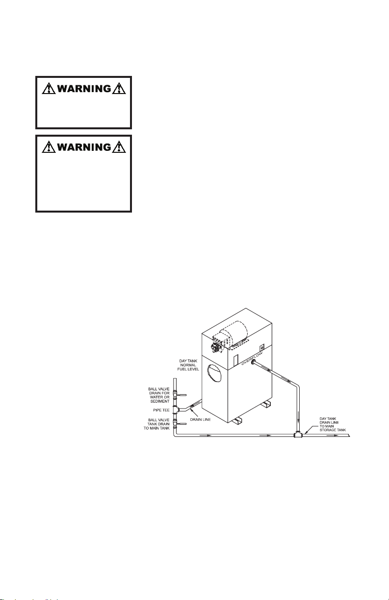
connected or is obstructed the tank will distort
and possibly rupture. In installations where the
main fuel tank is above ground the overow pipe
should be connected to an Overow Tank (Option
#390 Recommended). DO NOT INSTALL A
VALVE IN THE OVERFLOW LINE!
3. Attach the Day Tank Intake Line (ll pipe) from
the main fuel tank to the pump inlet. is is an
NPT internal connection. Use black pipe with
a union and size per the dimensional drawing.
Optional fuel strainer (Option 060) with #60 mesh
is recommended.
4. Attach the Engine Supply Line. is is an NPT
external connection. Use black pipe with a union
and size per the dimensional drawing in this
manual. Attach the Engine Return Line. is is an
NPT internal connection. Use black pipe with a
union and size per the dimensional drawing.
5. Attach the Engine Return Line. is is a NPT
internal connection. Use black pipe with a union
and size per the dimensional drawing.
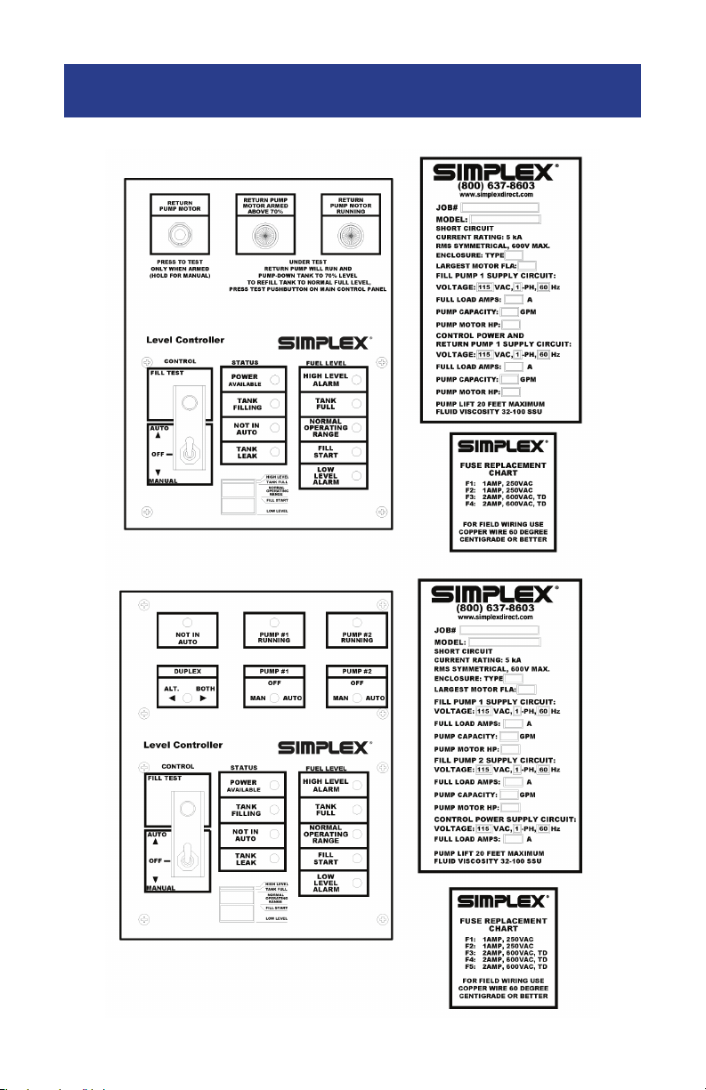
6. WARNING! Verify the Day Tank mode selector
switch is in the “O” position. Supply a 115-1-
60, 15A, circuit breaker protected circuit from
a reliable power bus to the control power ter-
minal board (TB”PS”) at terminals 1 and 2.
GROUND THE DAY TANK! Secure the conduit
end to the le side of the cover at the holes provid-
ed. Replace the cover.
Verify the Main Discon-
nect Switch and pump
Auto-Off-Run switches
are in the O position
before performing instal-
lation procedure.
Risk of electric shock!
More than one Discon-
nect Switch may be re-
quired to de-energize
the equipment before
servicing.
IMPORTANT NOTE!! The system shall be for use with fuel oil as
described by NFPA321, “Basic Classication of Flammable and Com-
bustible Liquids.” As dened by this standard, the fuel supply system
shall be for use with “combustible liquids,” those having a ash point
at or above 100°F and further dened as Class II or Class III liquids. In
no case shall a liquids having a ash point less than 100°F be used. In
every case, the system shall not be used or applied at a temperture in
excess of the ash point of the contents. Electrical equipment used in
the system shall be in accordance with NFPA30, section 5-7, wherein
it states “For areas where Class II or Class III liquids only are stored
or handled at a temperature below their ash points, the electrical
equipment may be installed in accordance with provisions of NFPA70,
National Code, for ordinary locations...”

9
7. e pump has been pre-lubricated with heavy oil
prior to shipment. Prime the system by using the
hand pump (Option 010 or 015) to transfer fuel
from the main tank to the Day Tank. If the Day
Tank is not equipped with a hand pump, remove
the tank inlet priming tee plug and ll the entire
inlet line with fuel. Replace the tee plug. Ener-
gize the Day Tank pump/motor by placing the
Day Tank mode selector switch in the automatic
position. Ensure that fuel is exiting the pump by
watching the clear pump outlet tubing. If not,
repeat this procedure and prime the pump also at
the pump priming tee. Make sure all unused Day
Tank holes are plugged, all pipe connections are
secure and no leaks are present. e Day Tank is
now ready for unattended automatic operation.
If the Day Tank has been stored for extended
periods of time pre-lube the pump with oil at the
pump priming tee.

10
Each tank and each compartment of a compartment
tank shall have provision for both normal and emer-
gency venting. A vent opening shall be in addition to
the lling and withdrawal openings. A vent opening
that provides both emergency and normal venting
shall have a capacity not less than that specied in
the Venting Capacity Table below. e wetted area
of a tank is calculated on the basis of 75% of the total
exposed area.
vent openIngS
VENTING CAPACITY
WETTED SURFACE,
SQUARE FEETb,c
VENTING CAPACITY,
CUBIC FEET PER HOURd, e
MINIMUM OPENING,
NOMINAL PIPE SIZE, INCHESf
20 21,100 2
30 31,600 2
40 42,100 3
50 52,700 3
60 63,200 3
70 73,700 4
80 84,200 4
90 94,800 4
100 105,000 4
120 126,000 5
140 147,000 5
160 168,000 5
180 190,000 5
200 211,000 6
250 239,000 6
300 265,000 6
350 288,000 8
400 312,000 8
500 354,000 8
600 392,000 8
700 428,000 8
800 462,000 8
900 493,000 8
1000 524,000 10
1200 557,000 10
1400 587,000 10
1600 614,000 10
1800 639,000 10
2000 662,000 10
2400 704,000 10
2800 and over 742,000 10
a At 14.7 psia and 60°F (101.4kPa and 16°C)
b Interpolate for intermediate values
c For SI units, m2 = ft2 /0.09
d These values taken from NFPA 30
e For SI units, m3/s = ft/hr X 0.03
f Thesepipesizesapplyonlytoopenventpipesofthespecieddiameternotmorethan12inches(0.3m)longanda
pressuretankofnotmorethan2.5psig(17.1kPa).Iftankistobeequippedwithventingdeviceoramearrestor,the
ventopeningistoaccomodatetheventingdeviceoramearrestorsizedinaccordancewithcolumn2ofthistable.

11
Day tank
pump prImIng
proCeDure
e Day Tank pump is shipped from the factory
pre-primed with SAE 30 oil. On initial start-up the
pump must be manually pre-primed. Do not prime
the system by running the pump motor! Normally
it is not necessary to ll the supply line with fuel to
prime the pump.
1. Remove the steel plug from the pump priming tee,
insert a short piece of pipe in the pump priming
tee and attach a reducing coupler or funnel.
2. Fill the line from the check valve to the pump with
fuel oil or lube oil. Energize the pump/motor and
observe fuel owing through the clear ex hose.
Allow the pipe to drain about halfway, then hold
your hand on the top of the pipe to temporarily
seal the open tee. e oil drawn into the pump
will act to seal the pump and allow a large vacuum
to be generated. Repeat as required until line is
primed. Aer pump is primed remove pipe/funnel
and replace plug in pump priming tee.
This is an industrial prod-
uct, not a consumer prod-
uct. It must be specied,
installed, operated and
maintained by individuals
equipped with the appro-
priate training and skills.
Attempting to pre-prime
the Day Tank delivery
system by running the
pump will cause serious
damage to the pump!

12
4 DAY TANK OPERATION
e control nameplate
consists of a durable,
fuel oil resistant, Lexan
membrane which contains
the Day Tank control
pushbutton, switch and
status indicators. e
control panel contains a
Fill Test pushbutton (hold
to test L.E.D. lamps), a
three position Day Tank
Auto-O-Manual switch,
and the following L.E.D.
lamps: Power Available,
Tank Filling, Tank Leak, Not In Auto (blinking),
High Level Alarm, Tank Full, Normal Operating
Range, Fill Start, and Low Level Alarm. Day Tank
operation is represented by the diagram in the lower
center of the nameplate.
e Day Tank control circuitry contains the fol-
lowing serviceable components: motor starting
contactor, and control fuses. Control fuses are 2A,
250VAC, ABC type, and the standard motor starting
contactor is a double pole, 24VDC coil, rated at 20A.
e prime controller in the Day Tank is the printed
circuit board. e Day Tank printed circuit board
is powered by a fused internal 24VDC, 2A, power
supply. e printed circuit board utilizes 24VDC
components to analyze the fuel level data it receives
from the four Day Tank fuel level sensors. e four
fuel level sensors together with the sensor mount-
ing plate comprise the fuel level sensor assembly.
When 120VAC, single phase, 60Hz control power is
supplied to the Day Tank control system the Power
Available L.E.D. is illuminated. See Parts Legend
Drawing for specic components used.
During automatic operation, the printed circuit
board energizes and de-energizes control relays,
the motor starter contactor, and the pump/motor to
automatically rell the Day Tank as fuel is consumed

13
automatIC
operatIon
Never use a Day Tank to
transfer or store Class
I, ammable, or liquids
with a ash point less
than 100°F. Ignition of
fuel can cause severe
personal injury or death!
Day Tanks are approved
for use with combustible
liquids (Class II or Class
III liquids) with a ash
point at or above 100°F
provided they are stored
below the ash point am-
bient temperature!
by the prime mover. Dry contacts for Low Fuel Level,
High Fuel Level, Leak Alarm, and Not In Auto relays
are wired to terminals 1-12 of terminal block TB‘A’
for customer use. e customer may utilize these
contacts to annunciate low fuel level and high fuel
level. Contacts are rated at the following specica-
tions: 5A@30VDC, 5A@125VAC.
e Day Tank operator selects the Day Tank oper-
ating mode via the three position Day Tank mode
selector toggle switch. e operator may choose
Automatic, Manual, or O. To alert the Day Tank op-
erator, the red Not In Auto lamp ashes continuously
when the Day Tank mode selector switch is not in the
Auto position. is is the only ashing lamp on the
control panel. Normally the mode selector switch is
le in the automatic position. Aer initial Day Tank
installation, priming, and ll, the controller printed
circuit board will energize and de-energize the Day
Tank pump/motor as determined by the opening and
closing of the fuel level sensors (25%-FS1, 50%-FS2,
90%-FS3, 95%-FS4). As the Day Tank continues to ll
and the fuel level reaches 50% capacity the Normal
Operating Range L.E.D. will be illuminated. e
Day Tank pump/motor will de-energize when the
fuel level reaches 90% (the Normal Operating Range
L.E.D. is extinguished and the Normal Maximum
L.E.D. is illuminated). During normal operation fuel
is consumed by the prime mover and the Day Tank
cycles between 50 and 90% capacity, energizing and
de-energizing the motor/pump as necessary. If the
pump/motor continues to run past the 90% capacity
level, normally open fuel level sensor FS4 will close
when 95% capacity is reached. At this point the High
Level Alarm L.E.D. will be illuminated and the pump
will de-energize.
A High Level alarm causes the Day Tank to enter a
new mode of operation dependent on the position of
the mode selector switch. Regardless of the opera-
tion mode, High Level indicates that fuel level has
reached or exceeded 95% capacity. e pump/motor
is de-energized and will remain locked out until the
Day Tank fuel level is decreased to 90% capacity or
less. e High Level L.E.D. will remain illuminated
until reset by the operator regardless of Day Tank
Day Tank operation is
automatic and the day
tank motor may start at
any time! After a motor
thermal overload reset
the motor may restart at
any time!
HIgH level fIll
DISableD

14
fuel level. If a High Level Alarm condition occurs
and the Day Tank fuel level is reduced to normal
levels the High Level L.E.D. will remain illuminated
until it is reset by the operator. e operator must
place the Day Tank mode selector switch in the O
position and then return it to the Manual or Auto-
matic position to reset the High Level failure. When
High Level is initiated while in Automatic Mode
the Day Tank will continue to operate normally and
cycle from 50% to 90% but the High Level L.E.D. will
remain illuminated until it is reset. When the High
Level mode is initiated while in Manual Mode the
Day Tank pump/motor will cycle between the 90%
and 95% levels as determined by fuel level sensors
FS3 and FS4. Aer the condition is corrected and the
control circuitry is returned to Auto the pump/motor
will resume normal operation and cycle between 50%
and 90%.Fuel level sensors FS1-FS3 (Low Fuel Level
Alarm, Fill Start, and Tank Full, respectively) have
normally closed contacts. FS4 (High Level Alarm)
is the only fuel level sensor with normally open
contacts.
e Fill Test pushbutton is a momentary type. It
may be used to provide a quick verication of overall
pump/motor/fuel level sensor operation when the
system is in the Auto mode. When the mode selec-
tor switch is placed in the O position, the Fill Test
pushbutton is disabled. When the mode selector
switch is in the Automatic position, the Fill Test
pushbutton is enabled.
e operator may energize the pump/motor with
the Test Fill pushbutton to test and cycle the Day
Tank through the specied capacity range. When the
pump is operated by continuously holding the Fill
Test pushbutton the pump/motor will continue to
run past the normal stop level until 95% capacity is
reached, at which point the pump/motor is de-en-
ergized and locked out by fuel level sensor FS4. e
High Level L.E.D. will be illuminated and the High
Level alarm relay will be energized. Contact rated 5A
@ 30 VDC, 5A @ 125VAC maximum.
During normal operation, the pump/motor is ener-
gized and the Fill Start L.E.D. is illuminated when
the Day Tank fuel level reaches 50% capacity. If the
fIll teSt
puSHbutton
low level fIll
alarm

15
pump/motor does not energize a low fuel level alarm
will be initiated when Day Tank fuel capacity reaches
the 25% level. e low fuel alarm relay LFR energizes,
the Low Level Alarm L.E.D. is illuminated, and LFR
dry contacts close. e Day Tank user may utilize
these contacts to sound an alarm horn or provide an
input to a remote annunciator. Contacts are 5A @
30VDC, 5A @ 125VAC maximum.
For manual (continuous run) operation, the Day
Tank operator must place the Day Tank mode se-
lector toggle switch in the Manual position. Manual
operation allows the Day Tank operator to energize
and run continuously the pump/motor independent
of fuel level sensors FS1-FS3. During manual opera-
tion the control panel L.E.D. lamps will continue to
annunciate fuel level to the Day Tank operator. e
Day Tank will continue to ll until 95% capacity is
reached at which time the High Level mode will be
initiated. e Day Tank pump/motor will be de-en-
ergized and locked out until Day Tank fuel level is
reduced to 90% capacity and fuel level sensor FS3
changes state. Until the alarm condition is corrected
and the control circuitry is reset to Auto the Day
Tank pump/motor will continue to cycle between the
90% and 95% levels. Upon return to Auto, the control
circuitry is reset and the pump/motor will resume
normal operation and cycle between 50% and 90%.
e momentary Fill Test pushbutton is also used to
test L.E.D. lamps on the control board. To use this
feature, press and hold the Fill Test pushbutton to il-
luminate the L.E.D. lamps. If desired, the lamps may
be tested without lling the tank further by placing
the mode switch in the “O” position before pressing
the Fill Test pushbutton.
Duplex pump options are used to increase the reli-
ability of a day tank system through the addition of a
second, back-up pump and level control. In a duplex
system, one pump is designated the “lead” pump and
the other is the “lag” pump. e lead pump automat-
ically rells the day tank over the tank’s normal op-
erating range of 50% to full. Normally, once the tank
has been initially lled, the fuel level should never
drop below 50%. Less than 50% is indicative of either
a failure of the lead pump or consumption in
manual
operatIon
lamp teSt
automatIC Duplex
pump Controller,
optIon 345

16
excess of pump capacity. e lag pump and its
separate level controller, acting as a backup senses a
drop in fuel level below 50% and starts the lag pump,
which then continues to run, along with the lead
pump, until the tank is full. Multi-function duplex
pump controller system providing selectable operat-
ing modes, including:
• Automatic lead pump alternating with automatic
lag pump back-up
• Automatic twin pump operation (both pumps run
simultaneously) automatic level control back-up
• Manual operation
Basic System includes the following:
• All controller features
• Manual o Auto Switch (1 per pump)
• Pump running indicators for each pump
• Two pumps, each with check valves
Operation: With the Duplex switch in the Alternate
position, Pump 1 will start at 50% and shut o at the
90% level. For utilization of both Pump 1 and Pump
2 simultaneously, switch to Both positions. In this
position Pump 1 and Pump 2 will start at the 50%
level and shut o at the 90% level.

17
When the Mode Selector switch is in the Manual
position all oatswitches, except the high fuel level
oatswitch are over-ridden, and either position
(Alternate or Both) may be selected. e pumps will
continue to run until Switch #1 is returned to the O
or Auto position or if a high fuel condition occurs.
For standard duplex operation, the Duplex switch
should be in the Alternate position and Mode Selec-
tor switch should be in the Auto position. Pump #1
will then start at 50% level and stop at the 90% level.
e next time fuel drops back to the 50% level Pump
#2 will start and then stop at the 90% level. Continu-
ing operation alternates between Pump #1 and Pump
#2. When the fuel drops to the 25% level, both pumps
will run simultaneously until the fuel level returns to
the 90% fuel level.
Operation: e control
switch should normally
be in the Auto position
and the Power Available
L.E.D. should be illumi-
nated. e level controller
is set to pump the tank to
virtually empty. ere-
fore, normally the tank
is empty and the Tank
Empty L.E.D. is illumi-
nated. If the adjacent Day
Tank should overll and
overow, oil will ow from the overow line of the
Day Tank to the inlet port of the overow-return
tank. Above empty level, oat switch FS3 will close.
At 20% level in the overow-return tank, oat switch
FS2 will close, activating the overow-return pump
which is installed on the tank. e Pump Start L.E.D.
will illuminate and the tank will be pumped-down
to empty. At empty level, oat switch FS3 will open
and stop the pump. If the level in the overow-re-
turn tank should continue to rise above the pump
start level, oat switch FS1 will close at the 30% level
activating the “high fuel level” alarm indicator and
remote signal contacts.
overflow -
return tank,
optIon 383
Day Tank operation is
automatic and the day
tank motor may start at
any time! After a motor
thermal overload reset
the motor may restart at
any time!

18
Normally the Day Tank operates automatically to
control the fuel level between the 50% and normal
full level, which is set at the position of the overow
or vent tting on the tank. An overll can occur if
the control switch is le in the Manual position, if
there is a leak in a control valve permitting gravity or
siphon ow of oil into the tank,
or if there is a control failure.
In the event of an overll, oat
switch FS4 will close, activating
the High Level Alarm L.E.D.
lamp on the control panel. In
addition, the ll pump will be
disabled. e tank should not
ll above this point, which is
approximately 1.0” above the
normal full level but 1.0-2.0”
below the top of the tank. With
the addition of option 390, the
overow-return pump will be
activated by the overow alarm
circuit and will operate as de-
scribed below.
Above 70% level, oat switch
closes and arms the overow-re-
turn controller, illuminating the
“overow return armed” indicator and enabling the
overow pump test pushbutton. Upon activation of
the overow alarm by oat switch FS4, as described
above, the over ow pump contactor will be ener-
gized, and the overow pump will run. e contac-
tor is latched-in via 70% level oat switch and the
tank will be pumped down to the 70% level. is is
intermediate in the normal operating range of 50% to
full and the tank should remain at this level; the rell
pump will not start until the tank reaches the 50%
level. As the overow pump is running, the “pump
running” L.E.D. will be illuminated.
To test the overow-return pump, press the Test
pushbutton. is pushbutton is armed only above
the 70% level, when the L.E.D. is illuminated. e
overow pump will pump-down the tank to the 70%
level. If desired, the tank can be relled to normal full
by pressing the test pushbutton on the control panel.
overflow -
return pump anD
Controller aDDeD
to tHe Day tank,
optIon 390
Table of contents
Other Simplex Industrial Equipment manuals

Simplex
Simplex 2120 Configuration guide

Simplex
Simplex 2120 Configuration guide

Simplex
Simplex LT0290 User manual

Simplex
Simplex Full-Size Fuelport User manual

Simplex
Simplex STS DAY TANK User manual

Simplex
Simplex LBD Series User manual

Simplex
Simplex VSH SUPER Manual

Simplex
Simplex Trident User manual

Simplex
Simplex 4090-9006 User guide

Simplex
Simplex 4604-9201 Quick guide