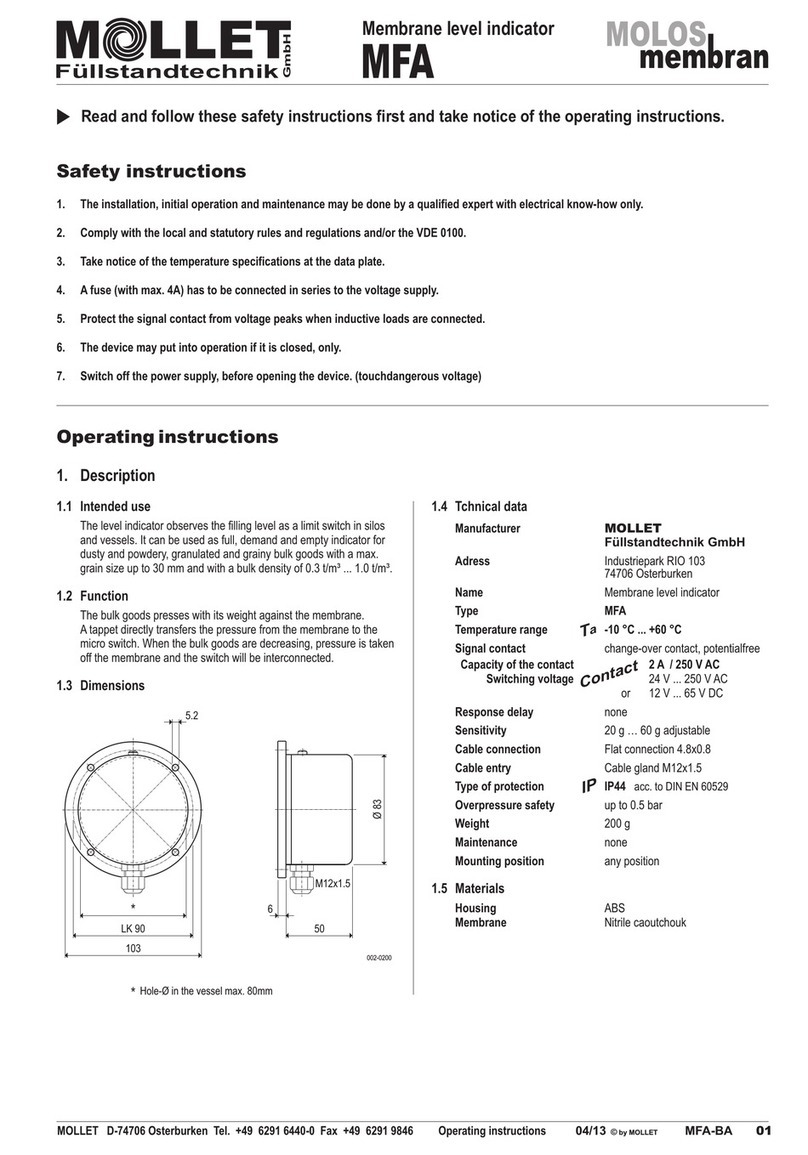
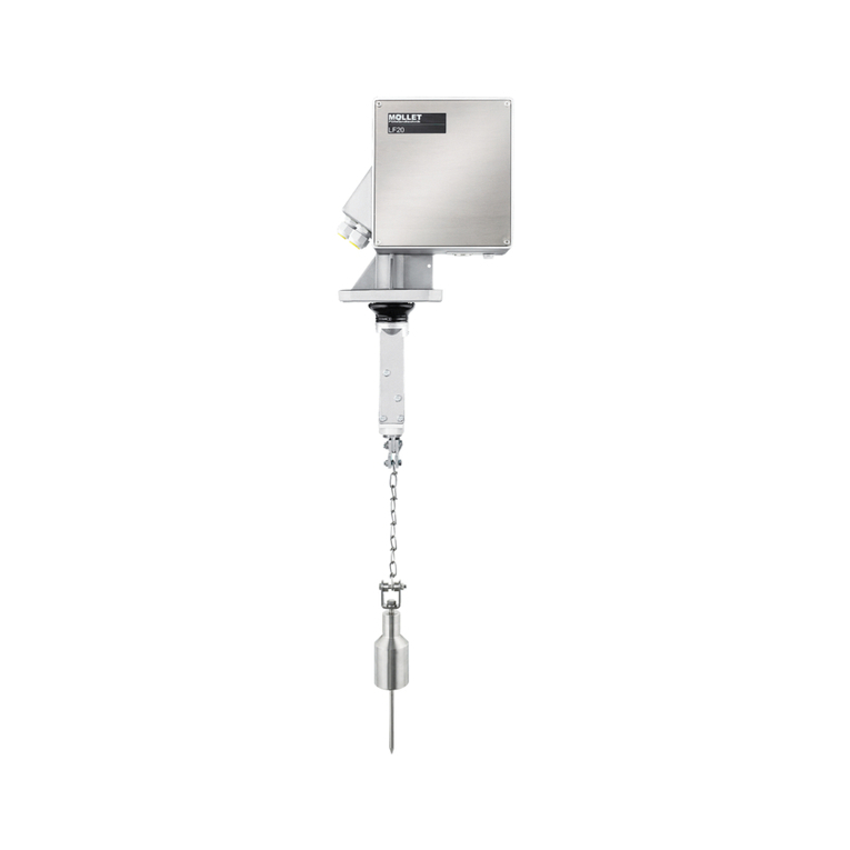
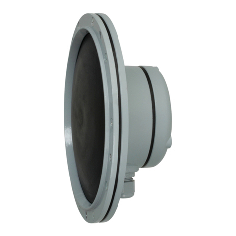
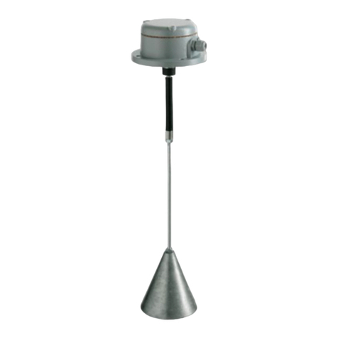
Mollet MOLOSwave MWF2 Series User manual

Index
Commissioning | Maintenance | Disposal . . . . . . . . . . . . . . . . . . . . . . . . . . . . . . . . . . . . . . . . . . . . . . . . . . 09
Data of manufacturer | Receiving department | Application | Function | Design . . . . . . . . . . . . . 03
Application data | Dimensions | Process connection | Hexagonal nuts . . . . . . . . . . . . . . . . . . . . . . 05
Safety instructions | Special conditions for ATEX-devices | Use . . . . . . . . . . . . . . . . . . . . . . . . . . . . . . 02
Technical data | Electrical data | Technical measuring data . . . . . . . . . . . . . . . . . . . . . . . . . . . . . . . . . . 04
Maximum forces | Mounting position . . . . . . . . . . . . . . . . . . . . . . . . . . . . . . . . . . . . . . . . . . . . . . . . . . . . . . . . 06
Installation advices . . . . . . . . . . . . . . . . . . . . . . . . . . . . . . . . . . . . . . . . . . . . . . . . . . . . . . . . . . . . . . . . . . . . . . . . . 07
Connection plan | Switching sequence | Electrical connection | Potential compensation . . . . . . . 09
Installation advices | Preparation of mounting | Mounting . . . . . . . . . . . . . . . . . . . . . . . . . . . . . . . . . . . . 08
Troubleshooting | Returns . . . . . . . . . . . . . . . . . . . . . . . . . . . . . . . . . . . . . . . . . . . . . . . . . . . . . . . . . . . . . . . . . 10
Page
M LLET
Füllstandtechnik
GmbH
03/20 © by MOLLET MWF-BA-01 01
MOLLET D-74706 Osterburken Tel. +49 6291 6440-0 Fax +49 6291 9846 Operating instruction
Operating instruction
MWF
Microwave level measurement
continuous level measuring for bulk goods

Microwave level measurement
MWF
02 MWF-BA-02 03/20 © by MOLLET
M LLET
Füllstandtechnik
GmbH
Operating instruction MOLLET D-74706 Osterburken Tel. +49 6291 6440-0 Fax +49 6291 9846
1.10 Changes and repairs of the device are allowed only in so far as it is permitted in the operating instructions.
1.1 The installation, initial operation and maintenance must be done by a qualified expert with electrical know-how.
1.2 Check before installation whether the measuring device is in compliance with the specification of the point of
measurement as process and ambient temperature as well as the measuring range.
1. Safety instructions
1.3 Use in potentially explosive atmospheres only devices with W - identification marking.
1.8 Put the device into operation only when the unit is closed and the cover sealing is intact.
1.9 The probe must not touch the wall, the bottom or other installations and may not come to the striking distance of them.
1.6 A fuse (max. 4 A) has to be connected in series to the voltage supply.
1.7 Check the cable entry, cable gland and clamping nut, to see if they are sitting correctly and are sealed.
1.5 Consider the data of the name plate on the device.
1.4 For the electrical connection take notice of the local and statutory rules and regulations and/or the VDE 0100.
Please, read and obey these safety instructions and the complete operating manual.
Prior to the use of the device in potentially explosive atmospheres please, read and obey the
and observe the operating instruction.
Special conditions and guidance for safe use
Explosions protection information
in the attached
- Removal, addition or modification of components as far as it is not described in the documentation of the manufacturer.
2.1 Intended use
- Violation of applicable standards and laws.
2.2 Normal operation
- Please operate the measuring device only according the intended use.
- Use the measuring device only within the specified temperature ranges for process and ambience.
- In case the measuring device becomes damaged, please stop operation immediately.
2. Use of the device
2.3 Improper use
- Ignoring safety regulations and operating instruction.
- Operation of the measuring device in inappropriate use.
- Installation of spare parts that are no original parts.
- Protect the electronics compartment against pollution.
- The device is used for continuous level measurement of bulk solids and liquids in silos and bins and tanks.

MWF
Microwave level measurement
Process connection
Feed-through
Wire rope probe
Tensioning weight
Rod probe
Housing with
sensor electronic
MWF27 MWF21
Connecting sleeve
002-1000
Counter nut
M LLET
Füllstandtechnik
GmbH
- Store the device at a place protected against moisture and dust.
- Temperature range for storage -40 °C ... +85 °C
- Take care that the probe will not be bended.
- Please check whether the supplied goods are incomplete or do
not comply the requirements as set out in your order.
4.1 Receipt of goods
4. Receiving department
- Please check whether packaging or content are damaged.
4.2 Storage
- For storage and transportation the measuring device has to be
packed shock-resistant.
Name of part MOLOSwave
Füllstandtechnik GmbH
Type MWF2 ...
3. Data of manufacturer
Microwave level measurement
Germany
Address Industriepark RIO 103
Manufacturer MOLLET
74706 Osterburken
7. Design
Two probe types are deliverable:
- 27 wire rope probe with tensioning weight for all tanks, silos and
vessels
- 21 rod probe, rigid for small vessels and bulk goods which exert
The MWF consists of three components:
- the probe mounted on the feed through.
- the housing with the sensor electronic,
- the process connection with the feed through,
low lateral forces at the probe and liquids.
electronic through the feed-through to the probe in the vessel with the
filling good and returned.
The high-frequency measuring signal will be transmitted by the sensor
MOLLET D-74706 Osterburken Tel. +49 6291 6440-0 Fax +49 6291 9846 Operating instruction
03/20 © by MOLLET MWF-BA-03 03
5. Application
Continuous level measurement with integrated limit level detection for
all bulk goods and liquids with a dielectric permittivity (DK value) of
minimum 1.8.
Independent from changing process characteristics as e.g. bulk density,
conductivity, temperature, pressure, moisture and dusty milieu.
Usable in small vessels just as in big silos and tanks, also with difficult
vessel geometry or nearby disturbing appliances.
and the impulses reflected and will be provided as a continuous
switching output signal can be set.
generated by the sensor electronic and propagated along the probe.
measurement signal through its analogue output. A freely positionable
6. Function
impulse energy will be reflected back up the probe to the electronic. The
level will be calculated by the time difference between the impulses sent
When these impulses hit the surface of the filling goods, a part of the
High-frequency electromagnetic impulses with low energy were

Microwave level measurement
MWF
04 MWF-BA-04 03/20 © by MOLLET
M LLET
Füllstandtechnik
GmbH
Tensioning weight Stainless steel 1.4571 / 316 Ti
Material Housing A1 Aluminium, coated RAL 7001
Connecting sleeve Stainless steel 1.4571 / 316 Ti
Rod probe Ø 6 mm
Flange F1 F70 1.4571 / 316 Ti or Aluminium
Wire rope Stainless steel 1.4401 / 316
Rod Stainless steel 1.4571 / 316 Ti
Hexagon nut G3 stainless steel 1.4571 / 316 Ti else
stainless steel 1.4301 / 304
Probe length [LS] 1.0 m ... 20.0 m
Tolerance of the lenghth [L] ± 10 mm
Feed-through PEEK
Process connection Stainless steel 1.4571 / 316 Ti
Flange F2 F100 1.4301 / 304 or Aluminium
8. Technical data
Housing A2 Stainless steel 1.4408 / 316
Probe length [LW] 0.5 m ... 3.0 m
Wire rope probe Ø 6 mm with tensioning weight Ø 30 mm
20 mA / 100 %
Depending on probe length
120
Reference point [R]
Sealing face of the thread
Inactive area
Adjustable
150
Probe length [L]
Maximum measuring range
Measuring range [M] 0 ... 100 %
Inactive area
Adjustable
Switch-points freely positionable
inside the measuring range [M]
4 mA / 0 %
Top edge tensioning weightFactory setting
002-1001
up to 5.0 m at 0.4 m
up to 10.0 m at 0.6 m
up to 15.0 m at 0.8 m
Factory setting [oMG] 20 mA depending on probe length for bulk
goods:
up to 20.0 m at 1.0 m
Inactive area wire rope rod
Measuring range (analog) [M] 4 mA lower current value [uMG]
down 150 mm 10 mm
Probe length [L] Reference point [R] to end of probe
up 120 mm 120 mm
10. Technical measuring data
max. measuring range < probe length
20 mA upper current value [oMG]
Factory setting [uMG] 4 mA Top edge tensioning weight
up to 3.0 m at 0.3 m
of filling level <1 m/s
or max. 0.03 % of measured value
or depending on customers request
Measureable changes
Repeatability <2 mm
Switch-points [oSA] [uSA] freely positionable inside measuring
(digital) range [M] with switch-hysteresis
Factory setting at 20% of probe length [L] below [R]
- upper and lower switch-point freely
selectable
Measuring accuracy ±3 mm
beneath reference point [R]
- minimum distance 3 mm
Temperature drift <0.2 mm/K
Resolution <1 mm (at reference conditions)
9. Electrical data
Supply voltage U 12 ... 30 V DC
N
(reverse-polarity protected)
Analog output signal (active) I 4 ... 20 mA (0 ... 100 %)
N
Switching output U 0 ... U
SN
Cable entry Cable gland M20x1.5
HIGH = U -2 V, LOW = 0 V ... 1 V
N
Load current <200 mA
Connection clamps 0.5 - 2 mm², screwless
Protection class I [
Power consumption <70 mA bei 24 V DC (no burden)
Type of protection IP66 and in vessel intrinsically safe „ia“
DC PNP (active)
NC or NO (selectable)
Factory setting NC
Response time <100 ms
Start-up time <6 sec
IP
Supply
Output
Contact
Operating instruction MOLLET D-74706 Osterburken Tel. +49 6291 6440-0 Fax +49 6291 9846
20 mA [oMG]
Upper switch-
point [oSA]
Filling level [F]
4 mA [uMG]
Lower switch-
point [uSA]

MWF
Microwave level measurement
M LLET
Füllstandtechnik
GmbH
MOLLET D-74706 Osterburken Tel. +49 6291 6440-0 Fax +49 6291 9846 Operating instruction
03/20 © by MOLLET MWF-BA-05 05
Ta -20 °C...+70 °C
(Process)
Ts -20 °C...+70 °C
or
Ts -40 °C...+150 °C
(Process)
p -1 bar...40 bar
002-1002
with order code E1 Ts -40 °C ... +150 °C
Ambient temperature Ta -20 °C ... +70 °C
with order code E0 Ts -20 °C ... +70 °C
Pressure in container p -1 bar ... 40 bar
Bulk goods temperature
Dielectric constant [εr] >1.8 (below 1.8 on request)
Probe length
Wire rope probe [LS] 1.0 m ... 20.0 m
Rod probe [LW] 0.5 m ... 3.0 m
SM2E G1¼ 50 8 G2I 1.4301
SM3E G1½ 55 8 G3I 1.4301
Art.-No. Thread For thread code
SM1E G1 41 6 G1I 1.4301
G2I G1¼ 50 Delivery including seals
G3I G1½ 55
13. Process connection - thread
Thread code Thread
G1I G1 46
14. Hexagonal nuts
92x88 92x88
25
25
140
140
150
M12
Ø30
25
Probe length [LS]
Probe length [LW]
Ø 6
001-0150
002-1004
12. Dimensions
11. Application data
T(Process)
Ta
p(Process)

~ ¾ ~ ¼
Filling cone
Discharge funnel
[B]
[E]
[A]
[C]
Adherence
Filling level [F]
Measuring height
002-1006
Microwave level measurement
MWF
M LLET
Füllstandtechnik
GmbH
06 MWF-BA-06 03/20 © by MOLLET
F1
F2
10 kN
6 Nm
Wire rope probe [LS] maximum tractive force F = 10 kN
1
ATTENTION:
In large silos a significant tractive force at the probe can be generated
by the bulk goods. The roof of the silo has to withstand this force.
Rod probe [LW] maximum side load F x LW = 6 Nm
2
[LS] [LW]
15. Maximum forces
002-1003
16. Mounting position
Probe should be placed in such a way that distance remains:
to plane metallic walls [A] >100 mm
to concrete walls [A] >500 mm
outside of plastic containers [D] >300 mm
to metallic hoppers and bottoms [E] >150 mm.
Exception: Probe will be fixed.
The probe must not touch metallic walls and bottoms.
By distances [C] [D] <300 mm
a disturbance signal suppression has to be done
(see parameterisation manual: Disturbance signal scan).
Mounting position should be selected in such a way that the proportion of
volumes of the filling cone and the discharge funnel will be vaguely
equalized (~ ¾ to ~ ¼ of silo diameter).
to adherences on the wall [B] >100 mm
Filling level [F]
to metallic installations [C] >300 mm
to metallic parts
Operating instruction MOLLET D-74706 Osterburken Tel. +49 6291 6440-0 Fax +49 6291 9846

wrong correct
[G]
Ø
[H]
MWF
Microwave level measurement
M LLET
Füllstandtechnik
GmbH
MOLLET D-74706 Osterburken Tel. +49 6291 6440-0 Fax +49 6291 9846 Operating instruction
03/20 © by MOLLET MWF-BA-07 07
Protruding nozzle diameter [G] 100 mm
Installation in consideration of filling
Protruding nozzle height [H] €200 mm
Installation with protruding nozzle
Choose the mounting position in such a way that the probe will not be
touched by the filling stream.
By use of thermally insulated vessels the nozzle should be also insulated
in order to avoid condensation.
The protruding nozzle should be short and inside flush with the silo roof.
Installation in silos made of concrete
In case of installation in a concrete floor the process connection should
be flush with the bottom edge of the floor.
Fixing of the wire rope probe could be necessary, when:
- wire rope probe touches sometimes the silo wall, the cone, internal
installations or other metallic parts,
Smaller diameters and heights >200 mm could restrict the measuring
capability.
- wire rope probe gets closer than 500 mm to a concrete wall.
For fixing a threat M12 is provided at the bottom of the tensioning weight.
- rope starts swinging due to vibrations,
The rope must be loose in order to avoid a heavy tensile load and with it
the danger of a rope breakage and
Installation with fastened wire rope probe
In silos made of concrete a minimum distance [A] of 500 mm between
the concrete wall and the probe should be kept. A distance of at least
1000 mm is recommended.
either reliably grounded or reliably isolated.
17. Installation advices
200 200
002-1006
002-1008
002-1009
002-1007
Reliably grounded fixing Reliably isolated fixing
Mounting
brackets
provided
on site
M12
Plastic rope

Microwave level measurement
MWF
Probe
M LLET
Füllstandtechnik
GmbH
08 MWF-BA-08 03/20 © by MOLLET
17. Installation advices
150
150
18
LK 170
001-0215
F2A = 15 mm
F2E = 12 mm
[R]
002-1005
MWF requires for correct functioning a metallic plate at the process
connection (near Reference point [R]).
Material Hood PVC, RAL 7001
Storm tape EDPM, weather-resisting
For protection against influence of weather the use of the weather
protection hood SH is recommended. It protects the sensor electronic
against overheating caused by direct solar radiation and avoids
condensation inside of the housing.
Use for mounting in open or non-metallic silos or bins the flange F2
(F100) made of Aluminium or stainless steel.
Protection against influence of weather
Instead of the flange a metal sheet with Ø >150 mm could be used as
well.
Mounting in open or non-metallic silos or bins
The reference point [R] is located above the flange.
002-1005
Storm tape
Thread of
feed-through
Counter nut
Bush
1
2
3
Weather protection
hood SH
Operating instruction MOLLET D-74706 Osterburken Tel. +49 6291 6440-0 Fax +49 6291 9846
- MWF has to be mounted vertically into the silo or vessel.
- 1 + 2 Screw the bush of the probe on the thread of the feed-through.
- MWF has to be mounted into empty silos or vessels in order to
make sure that wire rope probe hang vertically and don´t knot.
- Use for handling and wearing of the MWF the hexagon or the lower
section of the housing.
18. Preparation of mounting
In most cases the MWF is delivered completely preassembled.
- Do not turn the counter nut against the plastic of the feed-through.
This would result in permanently damaging of the sensor.
- 3 After the bush of the probe has been completely screwed, it has
to be secured with the counter nut.
If the device should be delivered with a detached probe, it has to be
attached at the thread of feed-through before mounting the device:
- Do not lift or handle MWF by its probe.
19. Mounting
- Select the mounting position according to the guidelines in chapter
16 and consider the installation advises in chapter 17.
- Screw the MWF into a screw socket or a flange with internal thread.
- Seal the process connection professional.
For most applications a sealing ring is part of the shipment.
- Do not screw in MWF by its housing. Use the hexagon at the
process connection.
Consider the process conditions like e.g.:
temperature, pressure and the characteristics of the process.

002-1005
001-1011
12 ... 30 V DC
4..20mA 12..30VDC
4 ... 20 mA
L +PE
002-AP05
MWF
Microwave level measurement
M LLET
Füllstandtechnik
GmbH
MOLLET D-74706 Osterburken Tel. +49 6291 6440-0 Fax +49 6291 9846 Operating instruction
03/20 © by MOLLET MWF-BA-09 09
21. Switching sequence
ATTENTION:
- Separate supply and signal wire (4-wire-technology)
- Operation via display device with 2-wire-technology not possible
- Connect grounding terminal with equalised
potential of the complete plant.
- Cable as short as possible
- Cable cross-section 2.5 mm²
Upper switch-point [oSA]
Lower switch-point [uSA]
Hysteresis
minimum 3 mm
Reference point [R]
NC NO
Switching behaviour at
23. Potential compensation
- Check the condition of the probe at least once a year. It must not be
cracked, twisted or disentangled.
25. Maintenance
- Level measurement device MWF is maintenance-free in operation
according the intended use.
- Level measurement device MWF can be recycled.
26. Disposal
- Disposal of the MWF is subject to the environmental legislation of
the respective country in effect for the operator's premises.
- Check the terminal assignments for correctness and the
cable glands for tightness.
- Switch on the power supply.
(Adaption of parameters only by changed process conditions and
after consulting MOLLET recommended)
24. Commissioning
All required parameters are programmed with factory settings.
- LED shines green and blinks after approx. 6 seconds.
- MWF is supplied ready for operation.
- MWF is in measuring mode.
- Be aware of the duly fit of the housing cover.
20. Connection plan
20.1 Connection drawing
2.3 Configure switch-points.
Upper switch-point [oSA] and
lower switch-point [uSA] of the
hysteresis are freely positionable
inside the measuring range.
For adaption of switch-points please
see parameterisation manual page 3:
22. Electrical connection
- Basic installation cable with solid or stranded wire is sufficient.
- Connect the MWF appropriate the connection plan.
- Recommended are wire-end ferrules without plastic collar.

Diagnosis with LED
Potential cause of error
What must be done?
LED doesn’t blink green
Wrong power supply Check the power supply 12…30V DC, the correct polarity and the cable
connection
Reset of MWF necessary
Interrupt the power supply in order to restart the device
If the LED is not blinking after the restart, please proceed with step 27.1
LED blinks green
DIP switch not in position 0 Put all DIP switch levers in the upper position off/0
Analysis device or display shows no or
wrong values
Measure current of the analogue output signal 4..20mA with a multimeter
1. If no current is measurable, interrupt the power supply in order to
restart the device
2. If no current is measurable after the restart, please proceed with step
27.1
3. If the measured current correlates to the filling level (e.g. 12 mA at a
filling height of 50 %), please check the analysis device, display or the
connection
LED blinks green and the
measured current doesn’t
correlate to the filling level
Probe touches silo wall, installed
equipment or nozzle
Remove probe from silo wall, installed equipment or nozzle and make
sure that the distance to them is sufficient
Cornice near the probe Remove cornice near the probe
Bridges in the silo Remove bridges in the silo and avoid bridge building
Larger caking to the probe Remove larger caking and clean the probe
Probe buckled Straighten the probe or renew it
Probe released from the device Install probe or renew it
Tensioning weight released from the
rope Install tensioning weight or renew it
Parameterisation not correct Adapt parameterisation after consultation of MOLLET
27.1 If the malfunction persists, the MWF has to be returned to MOLLET for review of the device function.
28. Returns
e. g. flammable, toxic, caustic or cancer-producing.
28.2 Furthermore please state:
- Chemical and physical characteristics of the the bulk goods or
liquid
28.1 Remove all adherent material residues of filling material from the
MWF. Be aware of seal grooves and cracks where material residues
could stick.
In particular if the bulk goods or liquids has been dangerous to
health,
- Operating time of the MWF
- Description of the failure occurred
- Description of the application
M LLET
Füllstandtechnik
GmbH
10 MWF-BA-10 03/20 © by MOLLET
27. Troubleshooting
Operating instruction MOLLET D-74706 Osterburken Tel. +49 6291 6440-0 Fax +49 6291 9846
Microwave level measurement
MWF

L
L
E
O
T
M
-
-
F
n
ü
e
l
l
k
s
r
t
a
u
n
b
r
d
e
t
t
e
s
c
h
O
n
6
i
k
0
7
G
4
m
7
-
b
D
H
H
ExB
Industriepark RIO 103
EU-Konformitätserklärung
EU-Declaration of Conformity
Wir/We MOLLET Füllstandtechnik GmbH
Angewandte harmonisierte Normen oder normative Dokumente:
declares under our sole responsibility, that the product:
And the devices with W - marking conform additional with the following European directive:
Und die Geräte mit W - Kennzeichnung entsprechen zusätzlich der folgenden Europäischen Richtlinie:
EMV-Richtlinie EMC directive 2014/30/EU
den folgenden Europäischen Richtlinien entspricht:
Applied harmonized standards or normative documents:
Tel. 06291 64400 Fax 06291 9846
erklären in alleiniger Verantwortung, dass das Produkt:
ATEX-Richtlinie ATEX directive 2014/34/EU
Angewandte harmonisierte Normen oder normative Dokumente:
TDR-Sensor zur kontinuierlichen Füllstandmessung /TDR sensor for continuous level measurement
Typ/Type MWF ...
conforms with the following European directives:
D-74706 Osterburken
Mikrowellen-Füllstandanzeiger / Microwave level indicator
Qualitätssicherung:
Osterburken, den 03.03.2020
Wolfgang Hageleit
DIN EN IEC 60079-0:2019 DIN EN 60079-11:2012 DIN EN 60079-31:2014
Geschäftsführer / managing director
Quality assurance: TÜV NORD CERT GmbH, 30159 Hannover (0044)
EU-Type Examination Certificate: IBExU11ATEX1108X
EG-Baumusterprüfbescheinigungsnummer:
Issued by: IBExU Institut für Sicherheitstechnik GmbH, 09599 Freiberg (0637)
Applied harmonized standards or normative documents:
Ausgestellt von:.
DIN EN 61326-1:2013
Niederspannungsrichtlinie Low voltage directive 2014/35/EU
DIN EN 61010-1:2020 DIN EN 60529:2014
EUKE-MWF
M LLET
Füllstandtechnik
GmbH
Diese Erklärung darf nur unverändert weiterverbreitet werden.
This declaration is only allowed to hand out in unchanged form.
91_EUKE-MWF_2_03-20
Index 2
Seite/Page 1 von/of 1
This manual suits for next models
2
Table of contents
Other Mollet Measuring Instrument manuals

Mollet
Mollet SES User manual

Mollet
Mollet SES User manual

Mollet
Mollet MFB User manual

Mollet
Mollet MSD-420 User manual

Mollet
Mollet MOLOS MFD User manual

Mollet
Mollet MOLOSwave MWF2-KIT Parts list manual

Mollet
Mollet LF20 Series User manual

Mollet
Mollet DF Series User manual

Mollet
Mollet DF Series User manual

Mollet
Mollet PF User manual