DALI DT8 RGBW LED Dimmer
Montageanleitung / Mounting Instruction
| 25 | 11 | 2021
Austria, 4600 Wels, Europastraße 45, T: +43 7242 698-0, M: office@moltoluce.com
DALI DT8 RGBW LED DIMMER
2 / 4
1
2
Betrieb
1. Einstellung der DALI-Adresse
1.1. Eine der beiden Tasten drücken und gedrückt halten, bis die numerische Digitalanzeige blinkt, dann die Taste loslassen.
1.2. Klicken Sie einmal auf eine der beiden Tasten, um eine Ziffer auszuwählen, klicken Sie erneut, um die Ziffer zu ändern, bis die gewünschte
DALI-Adresse erscheint.
Klicken Sie auf die erste Taste, um die „Zehner“-Position einzustellen, und auf die zweite Taste, um die „Einer“-Position einzustellen. Die
Adresse kann von 00~63 eingestellt werden.
1.3. Halten Sie dann eine der beiden Tasten gedrückt, bis die numerische Digitalanzeige aufhört zu blinken, um die Einstellung zu bestätigen.
Hinweis: Die DALI-Adresse kann manuell von 00-63-FF zugewiesen werden, werksseitig ist keine DALI-Adresse für den Dimmer zugewiesen und
auf dem Display erscheint FF.Die Einstellung der DALI-Adresse als FFsetzt den Dimmer auf die Werkeinstellungen zurück.
2. Sobald eine Adresse ausgewählt ist, haben alle vier Kanäle die gleiche Adresse. Wenn zum Beispiel der Dimmer 22 adressiert ist, haben CH1,
CH2, CH3 und CH4 die gleiche Adresse 22.
3. DALI-Adresse von DALI-Master zugewiesen
Die DALI-Adresse kann auch von einem DALI-Master-Controller automatisch zugewiesen werden, bitte lesen Sie die Bedienungsanleitungen der
kompatiblen DALI-Master für spezifische Vorgänge.
Hinweis: Die Digitalanzeige zeigt Auan, wenn der DALI-Master Adressen vergibt.
4. Tastdimmer-Modus
Wenn ein AC-Tastschalter angeschlossen ist, zeigt die Digitalanzeige „PD“ an, was „Push Dimmer Mode“ bedeutet,
Die Funktionen im Push-Dimmer-Modus sind wie folgt:
4.1. Klicken Sie auf die Taste, um EIN/AUS zu schalten
4.2. Halten Sie die Taste gedrückt, um die Lichtintensität auf das gewünschte Niveau zu erhöhen oder zu verringern, und lassen Sie sie dann
los.
Wiederholen Sie den Vorgang, um die Lichtintensität in die entgegengesetzte Richtung einzustellen. Der Dimmbereich reicht von 1% bis 100%.
4.2. Die Speicherfunktion nach dem Ausschalten oder einem Stromausfall ermöglicht es dem Gerät, sich den Status vor dem Ausschalten zu
merken.
Operation
1. Setting DALI address
1.1. Press and hold down any of the two buttons until numeric digital display flashes, then release the button.
1.2. Click any of the two buttons once to select a digit, click again to change the digit until the desired DALI address appears. Click first button
to set “tens” position and second button to set “units” position. The address can be set from 00~63.
1.3. Then press and hold down any of the 2 buttons until the numeric digital display stops flashing to confirm the setting.
Note: DALI address can be manually assigned from 00-63-FF, by factory defaults, no DALI address is assigned for the dimmer, and the display
shows FF. Setting DALI address as FFwill reset the dimmer to factory defaults.
2. Once an address is selected, all four channels‘ address will be the same. For example, if the dimmer is addressed to 22 on the display then
CH1, CH2, CH3, CH4 will be the same address 22.
3. DALI Address Assigned by DALI Masters
DALI address can also be assigned by DALI Master controller automatically, please refer to user manuals of compatible DALI Masters for specific
operations.
Note: The digital display will show Au when the DALI master is assigning addresses.
4. Push Dimmer Mode
While connected with a AC push switch, the digital display will show “PD” which means Push Dimmer Mode, operations under Push Dimmer Mode
are as follows:
4.1. Click the button to switch ON/OFF
4.2. Press and hold down the button to increase or decrease light intensity to desired level and release it, then repeat the operation to adjust
light intensity to opposite direction. The dimming range is from 1% to 100%.
4.2. Memory function after power off or power failure enables the device to memorize the status before power off while power on again.
DALI DT8 RGBW LED Dimmer 70040022
Function introduction
Important: Read All Instructions Prior to Installation
12-36V DC power input
Common Anode output(+)
• DO NOT install with power applied to device.
• DO NOT expose the device to moisture.
Product Data
Safety & Warnings
CH 1:R output(-)
CH 2 output:G (-)
CH 3 output:B (-)
CH 4 output:W (-)
Manual set button
Digital display
2 groups DALI/Push
signal input & output
DT8 DALI RGBW Dimmer
0-6 0-9
• In compliance with IEC 62386-101:2014, IEC 62386-102:2014, IEC 62386-207 Ed2, IEC 62386-209:2011
• Built-in DALI-2 interface, DALI DT8 device
• DALI DT8 device to control Red, Green, Blue and White output via a single DALI address
• 4 Channels constant voltage or constant current output
• Enables Dimming and color Adjustment
• Control of four PWM outputs R, G, B and W via DALI device type 8
• Color control as defined in the DALI specification device type 8
• Color type RGBW or XY coordinates can be preset by factory setting, default is RGBW
• Supports DT8 device commands, compatible with DALI masters that support DT8 commands
• Configuration via DALI master USB interface
• Numeric digital display for setting DALI address manually
• Waterproof grade: IP20
Operation
1. Setting DALI address
1.1. Press and hold down any of the two buttons until numeric digital display flashes, then release the button.
1.2. Click any of the two buttons once to select a digit, click again to change the digit until the desired DALI
2. Once an address is selected, all four channels' address will be the same. For example, if the dimmer is
addressed to 22 on the display then CH1, CH2, CH3, CH4 will be the same address 22.
Wiring Diagram
LED OUTPUT
12-36V DC
POWER INPUT
V-
V-
V+
V+
+
R-
G-
B-
W-
DA
DA
DA
DA
DALI
address appears. Click first button to set “tens” position and second button to set “units” position. The address
can be set from 00~63.
1.3. Then press and hold down any of the 2 buttons until the numeric digital display stops flashing to confirm the
setting.
Note: DALI address can be manually assigned from 00-63-FF, by factory defaults, no DALI address is
assigned for the dimmer, and the display shows . Setting DALI address as will reset the
dimmer to factory defaults.
3. DALI Address Assigned by DALI Masters
DALI address can also be assigned by DALI Master controller automatically, please refer to user manuals of
compatible DALI Masters for specific operations.
Note: The digital display will show When the DALI master is assigning addresses.
Input
Voltage Remarks
Output
Current
12-36VDC Constant voltage
4x(60-180)W
4x5A
Output
Power
12-36VDC Constant current
4x(4.2-12.6)W
4x350mA
12-36VDC Constant current
4x(8.4-25.2)W4x700mA
No.
1
2
3
Size(LxWxH)
170x53.4x28mm
170x53.4x28mm
170x53.4x28mm
2mA
DALI
Consumption
2mA
2mA
0.1%-100%
Dimming
Range
0.1%-100%
0.1%-100%
Ambient
Temperature
-20℃ ~ +50℃
-20℃ ~ +50℃
-20℃ ~ +50℃
DALI
2
PUSH D IM
L
N
DA
DA
4. Push Dimmer Mode
While connected with a AC push switch, the digital display will show “PD” which means Push Dimmer Mode,
operations under Push Dimmer Mode are as follows:
4.1. Click the button to switch ON/OFF
4.2. Press and hold down the button to increase or decrease light intensity to desired level and release it, then
repeat the operation to adjust light intensity to opposite direction. The dimming range is from 1% to 100%.
4.2. Memory function after power off or power failure enables the device to memorize the status before power
off while power on again.
DALI Master
L
N
GV+
V-
OUTPU T
INPUT
AC Power
50/60Hz
12V/24V/36V
CV PSU
Conn ec t with RGBW L ED Strip
V+ V+
R- R-
G- G-
B- B-
W- W-
Conn ec t with RGBW L ED Strip
V+ V+
R- R-
G- G-
B- B-
W- W-
DT8 DAL I RGBW Dimmer
0-6 0 -9
LED OUT PU T
12-36 V DC
POWER INPUT
V-
V-
V+
V+
+
R-
G-
B-
W-
DA
DA
DA
DA
DALI DALI
PUS H DIM
L
N
DA
DA
DT8 DAL I RGBW Dimmer
0-6 0 -9
LED OUTPUT
12-36 V DC
POWER INPUT
V-
V-
V+
V+
+
R-
G-
B-
W-
DA
DA
DA
DA
DALI DALI
PUS H DIM
L
N
DA
DA
DALI DT8 RGBW LED Dimmer 70040022
Function introduction
Important: Read All Instructions Prior to Installation
12-36V DC power input
Common Anode output(+)
• DO NOT install with power applied to device.
• DO NOT expose the device to moisture.
Product Data
Safety & Warnings
CH 1:R output(-)
CH 2 output:G (-)
CH 3 output:B (-)
CH 4 output:W (-)
Manual set button
Digital display
2 groups DALI/Push
signal input & output
DT8 DALI RGBW Dimmer
0-6 0-9
• In compliance with IEC 62386-101:2014, IEC 62386-102:2014, IEC 62386-207 Ed2, IEC 62386-209:2011
• Built-in DALI-2 interface, DALI DT8 device
• DALI DT8 device to control Red, Green, Blue and White output via a single DALI address
• 4 Channels constant voltage or constant current output
• Enables Dimming and color Adjustment
• Control of four PWM outputs R, G, B and W via DALI device type 8
• Color control as defined in the DALI specification device type 8
• Color type RGBW or XY coordinates can be preset by factory setting, default is RGBW
• Supports DT8 device commands, compatible with DALI masters that support DT8 commands
• Configuration via DALI master USB interface
• Numeric digital display for setting DALI address manually
• Waterproof grade: IP20
Operation
1. Setting DALI address
1.1. Press and hold down any of the two buttons until numeric digital display flashes, then release the button.
1.2. Click any of the two buttons once to select a digit, click again to change the digit until the desired DALI
2. Once an address is selected, all four channels' address will be the same. For example, if the dimmer is
addressed to 22 on the display then CH1, CH2, CH3, CH4 will be the same address 22.
Wiring Diagram
LED OUTP UT
12-36V DC
POWER INPUT
V-
V-
V+
V+
+
R-
G-
B-
W-
DA
DA
DA
DA
DALI
address appears. Click first button to set “tens” position and second button to set “units” position. The address
can be set from 00~63.
1.3. Then press and hold down any of the 2 buttons until the numeric digital display stops flashing to confirm the
setting.
Note: DALI address can be manually assigned from 00-63-FF, by factory defaults, no DALI address is
assigned for the dimmer, and the display shows . Setting DALI address as will reset the
dimmer to factory defaults.
3. DALI Address Assigned by DALI Masters
DALI address can also be assigned by DALI Master controller automatically, please refer to user manuals of
compatible DALI Masters for specific operations.
Note: The digital display will show When the DALI master is assigning addresses.
Input
Voltage Remarks
Output
Current
12-36VDC Constant voltage
4x(60-180)W
4x5A
Output
Power
12-36VDC Constant current
4x(4.2-12.6)W
4x350mA
12-36VDC Constant current
4x(8.4-25.2)W4x700mA
No.
1
2
3
Size(LxWxH)
170x53.4x28mm
170x53.4x28mm
170x53.4x28mm
2mA
DALI
Consumption
2mA
2mA
0.1%-100%
Dimming
Range
0.1%-100%
0.1%-100%
Ambient
Temperature
-20℃ ~ +50℃
-20℃ ~ +50℃
-20℃ ~ +50℃
DALI
2
PUS H DIM
L
N
DA
DA
4. Push Dimmer Mode
While connected with a AC push switch, the digital display will show “PD” which means Push Dimmer Mode,
operations under Push Dimmer Mode are as follows:
4.1. Click the button to switch ON/OFF
4.2. Press and hold down the button to increase or decrease light intensity to desired level and release it, then
repeat the operation to adjust light intensity to opposite direction. The dimming range is from 1% to 100%.
4.2. Memory function after power off or power failure enables the device to memorize the status before power
off while power on again.
DALI Master
L
N
GV+
V-
OUTPUT
INPUT
AC Power
50/60Hz
12V/24V/36V
CV PSU
Con ne ct w ith R GB W LE D Str ip
V+ V+
R- R-
G- G-
B- B-
W- W-
Con ne ct w ith R GB W LE D Str ip
V+ V+
R- R-
G- G-
B- B-
W- W-
1. With DALI Bus
DT8 DALI R GB W Di mm er
0-6 0 -9
LED O UTPUT
12- 36V DC
POWER INPUT
V-
V-
V+
V+
+
R-
G-
B-
W-
DA
DA
DA
DA
DALI DALI
PUSH D IM
L
N
DA
DA
DT8 DALI R GB W Di mm er
0-6 0 -9
LED OUTPUT
12- 36V DC
POWER INPUT
V-
V-
V+
V+
+
R-
G-
B-
W-
DA
DA
DA
DA
DALI DALI
PUSH D IM
L
N
DA
DA
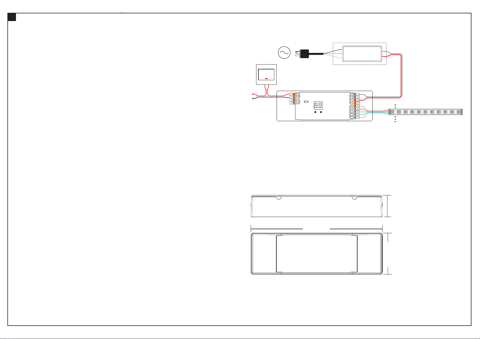
Schaltplan
Wiring Diagram
1. Mit DALI Bus
With DALI Bus
Anmerkung:
1) Der DT8-Farbtyp des Dimmers kann RGBW oder XY-Koordinaten sein, die werkseitig voreingestellt werden können.
2) Beim Farbtyp XY-Koordinaten kann der 4. W-Kanal nur zusammen mit RGB-Kanälen gesteuert werden.
3) Nur wenn der Koordinatenpunkt in dem Bereich liegt, in dem sich die drei Farben R, G, B mischen, wird der W-Kanal eingeschaltet.
4) Die Intensität des W-Kanals steigt nur an, wenn die Intensität der drei Farben R, G und B gleichzeitig ansteigt.
5) Die Intensität des W-Kanals sinkt nur, wenn die Intensität der drei Farben R, G und B gleichzeitig sinkt.
6) Wenn die Steuerung über ein XY-Touchpanel erfolgt, verwenden Sie die Taste W auf dem Panel, um RGB zu mischen und so den 4. Kanal
W einzuschalten.
Note:
1) DT8 color type of the dimmer can be RGBW or XY coordinates, which can be preset by factory setting.
2) For color type XY coordinates, the 4th W channel can only be controlled together with RGB channels.
3) Only when the coordinate point at the area where R, G, B three colors mix color will W channel turn on.
4) W channel intensity will go up only as R, G, B three colors’ intensity goes up simultaneously.
5) W channel intensity will go down only as R, G, B three colors’ intensity goes down simultaneously.
6) If controlled by XY type touch panel, use W button on the panel to mix RGB thus turn on 4th channel W.