Monacor IMG STAGELINE LC-1LED User manual

DMX-Steuerpult für LED-Scheinwerfer
Bitte lesen Sie diese Anleitung vor dem Betrieb gründlich durch und
heben Sie sie für ein späteres Nachlesen auf.
1 Verwendungsmöglichkeiten
Dieses kompakte Steuerpult ermöglicht die einfache Bedienung von
LED-Scheinwerfern mit getrennt steuerbaren Grundfarben (RGB)
sowie Scheinwerfern mit zusätzlichen weißen LEDs (RGBW). Generell
können 4 DMX-Kanäle unabhängig gesteuert werden. Zudem bietet
das Pult speziell für die LED-Scheinwerfer eigene Farbwechselpro-
gramme und Stroboskopeffekte.
2 Hinweise für den sicheren Gebrauch
Die Geräte (Steuerpult und Netzgerät) entsprechen allen relevanten
Richtlinien der EU und sind deshalb mit gekennzeichnet.
Beachten Sie auch unbedingt die folgenden Punkte:
GVerwenden Sie die Geräte nur im Innenbereich und schützen Sie sie
vor Tropf- und Spritzwasser, hoher Luftfeuchtigkeit und Hitze (zu-
lässiger Einsatztemperaturbereich 0 – 40 °C).
GNehmen Sie das Steuerpult nicht in Betrieb und ziehen Sie sofort das
Netzgerät aus der Steckdose,
1. wenn sichtbare Schäden an einem der Geräte vorhanden sind,
2. wenn nach einem Sturz oder Ähnlichem der Verdacht auf einen
Defekt besteht,
3. wenn Funktionsstörungen auftreten.
Geben Sie die Geräte in jedem Fall zur Reparatur in eine Fachwerk-
statt.
GVerwenden Sie für die Reinigung nur ein trockenes, weiches Tuch,
niemals Wasser oder Chemikalien.
GWerden die Geräte zweckentfremdet, nicht richtig angeschlossen,
falsch bedient oder nicht fachgerecht repariert, kann keine Haftung
für daraus resultierende Sach- oder Personenschäden und keine
Garantie für die Geräte übernommen werden.
3 Inbetriebnahme
1) Zur Stromversorgung das beiliegende Netzgerät an die Buchse
„9 –12 V “ (9) und an eine Steckdose (230 V~/50 Hz) anschließen.
2) Die XLR-Buchse DMX OUT (8) mit dem Eingang des (ersten) LED-
Scheinwerfers verbinden. Zum Anschluss möglichst ein spezielles
Kabel für hohen Datenfluss verwenden. Abgeschirmte Mikrofonka-
bel mit 2 × 0,22 mm2Mindestleitungsquerschnitt und geringer Kapa-
zität sollten nur bei einer Gesamtkabellänge bis 100 m verwendet
werden. Bei Leitungslängen ab 150 m wird das Zwischenschalten
eines DMX-Aufholverstärkers empfohlen (z. B. SR-103DMX).
Sollen mehrere Scheinwerfer synchron gesteuert werden, den
DMX-Ausgang des ersten Scheinwerfers mit dem DMX-Eingang des
nächsten Scheinwerfers verbinden. Dessen Ausgang wieder mit
dem Eingang des nachfolgenden Gerätes verbinden usw., bis max.
32 Geräte in einer Kette angeschlossen sind. Besonders bei langen
Verbindungskabeln wird empfohlen, einen Abschlussstecker (z. B.
DLT-123) in die Ausgangsbuchse des letzten Gerätes zu stecken.
3) Die Startadresse aller LED-Scheinwerfer auf 1 einstellen.
4 Bedienung
Das Steuerpult mit dem Schalter POWER (10) einschalten. Die LED
RGBD oder RGBW (7) leuchtet.
Nach dem Betrieb das Pult mit dem Schalter POWER ausschalten.
Wird das Steuerpult längere Zeit nicht benutzt, das Netzgerät aus der
Sollen die Geräte endgültig aus dem Betrieb genommen wer-
den, übergeben Sie sie zur umweltgerechten Entsorgung
einem örtlichen Recyclingbetrieb.
WARNUNG Das Steckernetzgerät wird mit lebensgefährlicher Netz-
spannung versorgt. Nehmen Sie deshalb niemals selbst
Eingriffe am Netzgerät vor. Es besteht die Gefahr eines
elektrischen Schlages.
LC-1LED
Bestellnummer 38.6210
wwwwww..iimmggssttaaggeelliinnee..ccoomm
Steckdose ziehen, denn es verbraucht auch bei ausgeschaltetem Pult
einen geringen Strom.
4.1 Manuelle Steuerung
Mit den Reglern R, G, B und W/D (1) jeweils die gewünschte Helligkeit
für Rot, Grün, Blau und Weiß einstellen. Bei Scheinwerfern ohne weiße
LEDs liegt auf dem 4. Kanal häufig die Dimmerfunktion (D), teilweise
mit zusätzlichen Funktionen, wie Stroboskop oder Musiksteuerung.
4.2 Kanal-Modus wählen
Für die Funktionen in Kapitel 4.3 bis 4.5 ist es erforderlich, den Schein-
werfertyp am Pult zu wählen. Dieser kann mit der Taste CHANNEL
MODE (7) umgeschaltet werden. Die LEDs über dem Schalter zeigen
die aktuelle Einstellung:
RGBD für RGB-Scheinwerfer mit Dimmerfunktion auf dem 4. Kanal
(außer bei manueller Steuerung wird auf Kanal 4 immer der
Wert 255 gesendet)
RGBW für RGBW-Scheinwerfer
4.3 Farbmischer
Zur schnellen Wahl eines Farbtons bei voller Helligkeit den MIX-Reg-
ler (2) verwenden.
4.4 Farbwechselprogramme
Zum Starten eines der 8 automatischen Farbwechselprogramme, die-
ses mit dem Regler MACRO (3) einstellen. Der Regler SPEED (4)
bestimmt dabei die Ablaufgeschwindigkeit.
4.5 Stroboskop-Effekte
1) Die Art des Effektes (1 = Einzelblitze, 2 = Salven, 3 = Anschwellen,
4 = Abschwellen) mit dem Regler STROBE EFFECT (5) wählen. Die
Blitzhäufigkeit lässt sich innerhalb der Einstellbereiche verändern.
2) Zum Auslösen des Effektes die Taste STROBE (6) gedrückt halten.
5 Technische Daten
Steuerprotokoll: . . . . . . . . . . . DMX512, 4 Kanäle
Stromversorgung: . . . . . . . . . 9 – 12 V /300 mA über beiliegendes
Netzgerät an 230 V~/50 Hz
Abmessungen, Gewicht: . . . . 200 × 90 × 55 mm, 786 g
Änderungen vorbehalten.
MACRO Farbfolge (MACRO 1 – 4 mit Überblendungen)
1, 5 Rot, Grün
2, 6 Rot, Blau
3, 7 Grün, Blau
4, 8 Rot, Grün, Blau, [Weiß]
1234567
8910
®
MONACOR INTERNATIONAL GmbH & Co. KG
•
Zum Falsch 36
•
28307 Bremen
•
Germany
Copyright
©
by MONACOR INTERNATIONAL. All rights reserved. A-1360.99.01.09.2012
D A CH

DMX Control Panel for LED Spotlights
Please read these operating instructions carefully prior to operation
and keep them for later reference.
1 Applications
This compact control panel allows easy operation of LED spotlights
with separately controllable primary colours (RGB) and spotlights with
additional white LEDs (RGBW). In general, 4 DMX channels may be
controlled independently. In addition, the panel offers individual colour
changing programmes and stroboscope effects especially for the LED
spotlights.
2 Safety Notes
The units (control panel and power supply unit) correspond to all rele-
vant directives of the EU and are therefore marked with .
It is essential to observe the following items:
GThe units are suitable for indoor use only. Protect them against drip-
ping water and splash water, high air humidity, and heat (admissible
ambient temperature range 0 – 40 °C).
GDo not set the control panel into operation, and immediately discon-
nect the power supply unit from the mains socket if
1. there is visible damage to one of the units,
2. a defect might have occurred after a drop or similar accident,
3. malfunctions occur.
The units must in any case be repaired by skilled personnel.
GFor cleaning only use a dry, soft cloth, never use water or chemicals.
GNo guarantee claims for the units and no liability for any resulting per-
sonal damage or material damage will be accepted if the units are
used for other purposes than originally intended, if they are not cor-
rectly connected or operated, or not repaired in an expert way.
3 Setting into Operation
1) For power supply connect the power supply unit provided to the jack
“9 –12 V ” (9) and to a socket (230 V~/50 Hz).
2) Connect the XLR jack DMX OUT (8) to the input of the (first) LED
spotlight. For connection, use a special cable for high data flow, if
possible. Microphone cables with screening and a minimum cross
section of 2 × 0.22 mm2and a low capacity should only be used for
a total cable length of up to 100 m. For cable lengths exceeding
150 m, it is recommended to insert a DMX level matching amplifier
(e. g. SR-103DMX).
To control several spotlights in sync, connect the DMX output of
the first spotlight to the DMX input of the next spotlight. Connect its
output again to the input of the following unit etc., until 32 units as a
maximum are connected in a chain. Especially for long connection
cables it is recommended to connect a terminating plug (e. g. DLT-
123) to the output jack of the last unit.
3) Set the start address of all LED spotlights to 1.
4 Operation
Switch on the control panel with the POWER switch (10). The LED
RGBD or RGBW (7) lights up.
After operation switch off the panel with the POWER switch. If the
control panel is not in use for a longer period of time, disconnect the
power supply unit from the socket; even with the panel switched off, the
power supply unit will have a low power consumption.
If the units are to be put out of operation definitively, take them
to a local recycling plant for a disposal which is not harmful to
the environment.
WARNING
The plug-in power supply unit is supplied with hazardous
mains voltage. Leave servicing to skilled personnel only.
Inexpert handling may cause an electric shock hazard.
LC-1LED
Order No. 38.6210
wwwwww..iimmggssttaaggeelliinnee..ccoomm
4.1 Manual control
Adjust the desired brightness for red, green, blue and white in each
case with the controls R, G, B and W/D (1). For spotlights without white
LEDs the dimmer function (D) is often on the 4th channel, partly with
additional functions, like stroboscope or music control.
4.2 Selecting the channel mode
For the functions in chapters 4.3 to 4.5 it is necessary to select the spot-
light type on the panel. This can be switched over with the button
CHANNEL MODE (7). The LEDs above the switch show the present
adjustment:
RGBD for RGB spotlights with dimmer function on the 4th channel
(except for manual control, the value 255 is always trans-
mitted on channel 4)
RGBW for RGBW spotlights
4.3 Colour mixer
For fast selection of a colour shade at full brightness use the MIX con-
trol (2).
4.4 Colour changing programmes
To start one of the 8 automatic colour changing programmes, adjust it
with the control MACRO (3). The control SPEED (4) defines the pro-
gramme speed.
4.5 Stroboscope effects
1) Select the type of the effect (1 = individual flashes, 2 = salvos,
3 = increasing, 4 = decreasing) with the control STROBE EFFECT (5).
The flash frequency can be changed within the adjusting ranges.
2) To activate the effect, keep the button STROBE (6) pressed.
5 Specifications
Control protocol: . . . . . . . . . . DMX512, 4 channels
Power supply: . . . . . . . . . . . . 9 – 12 V /300 mA via power supply unit
provided, connected to 230 V~/50 Hz
Dimensions, weight: . . . . . . . 200 × 90 × 55 mm, 786 g
Subject to technical modification.
MACRO Colour sequence (MACRO 1 – 4 with crossfadings)
1, 5 red, green
2, 6 red, blue
3, 7 green, blue
4, 8 red, green, blue, [white]
1234567
8910
®
MONACOR INTERNATIONAL GmbH & Co. KG
•
Zum Falsch 36
•
28307 Bremen
•
Germany
Copyright
©
by MONACOR INTERNATIONAL. All rights reserved. A-1360.99.01.09.2012
GB

Contrôleur DMX pour projecteur à LEDs
Veuillez lire la présente notice avec attention avant le fonctionnement
et conservez-la pour pouvoir vous y reporter ultérieurement.
1 Possibilités dʼutilisation
Ce contrôleur compact permet une utilisation simple de projecteurs à
LEDs avec couleurs de base (RVB) gérables séparément et de projec-
teurs avec LEDs blanches supplémentaires (RVBW). 4 canaux DMX
peuvent, en règle générale, être gérés indépendamment. De plus, le
pupitre propose spécialement pour les projecteurs à LEDs, des pro-
grammes individuels de changement de couleurs et dʼeffets de strobo-
scope.
2 Conseils importants dʼutilisation
Les appareils (contrôleur et bloc secteur) répondent à toutes les direc-
tives nécessaires de lʼUnion européenne et portent donc le symbole .
Respectez scrupuleusement les points suivants :
GLes appareils ne sont conçus que pour une utilisation en inté-
rieur. Protégez-les de tout type de projections dʼeau, des éclabous-
sures, dʼune humidité élevée dʼair et de la chaleur (plage de tempé-
rature de fonctionnement autorisée : 0 – 40 °C).
GNe faites pas fonctionner le contrôleur et débranchez immédiate-
ment le bloc secteur de la prise lorsque :
1. des dommages visibles apparaissent sur un des appareils,
2. après une chute ou un cas similaire, vous avez un doute sur lʼétat
de lʼappareil,
3. des dysfonctionnements apparaissent.
Dans tous les cas, les dommages doivent être réparés par un tech-
nicien spécialisé.
GPour le nettoyage, utilisez un chiffon sec et doux, en aucun cas de
produits chimiques ou dʼeau.
GNous déclinons toute responsabilité en cas de dommages matériels
ou corporels résultants si les appareils sont utilisés dans un but autre
que celui pour lequel ils ont été conçus, sʼils ne sont pas correcte-
ment branchés, utilisés ou ne sont pas réparés par une personne
habilitée ; en outre, la garantie deviendrait caduque.
3 Mise en service
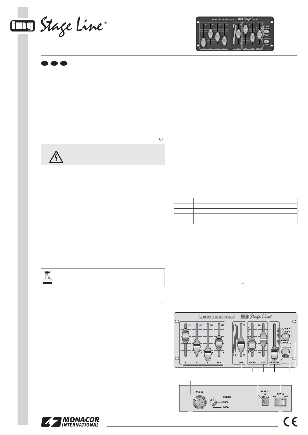
1) Pour lʼalimentation, reliez le bloc secteur livré à la prise “9 –12 V ”
(9) et à une prise secteur 230 V~/50 Hz.
2) Reliez la prise XLR DMX OUT (8) à lʼentrée du (premier) projecteur
à LEDs. Pour le branchement, il est recommandé dʼutiliser un câble
spécifique pour des flots importants de données. Lʼemploi de câbles
micro usuels avec blindage et une section de 2 × 0,22 mm2au moins
et la capacité la plus faible possible nʼest recommandé que pour des
longueurs de câble de 100 m maximum. Pour des longueurs de liai-
son à partir de 150 m, il est recommandé dʼinsérer un amplificateur
DMX de signal (par exemple SR-103DMX).
Si plusieurs projecteurs doivent être gérés de manière syn-
chrone, reliez la sortie DMX du premier projecteur à lʼentrée DMX du
projecteur suivant. Reliez sa sortie à lʼentrée de lʼappareil suivant
etc. jusquʼà ce que 32 appareils au plus forment une chaîne. Spé-
cialement pour des câbles longs, il est recommandé de placer un
bouchon (p. ex. DLT-123) dans la prise de sortie du dernier appareil.
3) Réglez lʼadresse de démarrage de tous les projecteurs sur 1.
4 Fonctionnement
Allumez le contrôleur avec lʼinterrupteur POWER (10). La LED RGBD
ou RGBW (7) brille.
Après le fonctionnement, éteignez le contrôleur avec lʼinterrupteur
POWER. En cas de non utilisation prolongée du contrôleur, débran-
Lorsque les appareils sont définitivement retirés du service,
vous devez les déposer dans une usine de recyclage adaptée
pour contribuer à leur élimination non polluante.
AVERTISSEMENT Le bloc secteur est alimenté par une tension secteur
dangereuse. Ne touchez jamais lʼintérieur de lʼappa-
reil, en cas de mauvaise manipulation, vous pourriez
subir une décharge électrique.
LC-1LED
Réf. num. 38.6210
wwwwww..iimmggssttaaggeelliinnee..ccoomm
chez le bloc secteur car, même si le contrôleur est éteint, il a une faible
consommation.
4.1 Gestion manuelle
Avec les réglages R, G, B et W/D (1), réglez la luminosité voulue pour
le rouge, vert, bleu et blanc. Pour des projecteurs sans LEDs blanches,
la fonction dimmer (D) est souvent sur le canal 4, parfois avec des fonc-
tions supplémentaires telles que stroboscope ou gestion par la musique.
4.2 Sélection du mode canal
Pour les fonctions décrites dans les chapitres 4.3 à 4.5, il est indispen-
sable de sélectionner le type de projecteur sur le contrôleur. Il peut être
commuté avec la touche CHANNEL MODE (7). Les LEDs au-dessus
de lʼinterrupteur montrent le réglage actuel.
RGBD pour projecteurs RVB avec fonction dimmer sur le canal 4
(excepté pour une gestion manuelle, la valeur 255 est tou-
jours envoyée sur le canal 4).
RGBW pour projecteurs RVBW
4.3 Mixage des couleurs
Pour une sélection rapide dʼune teinte de couleur avec luminosité
pleine, utilisez le réglage MIX (2).
4.4 Programmes de changement de couleurs
Pour démarrer un des 8 programmes automatiques de changement de
couleurs, réglez-le avec le réglage MACRO (3). Le réglage SPEED (4)
détermine la vitesse de défilement.
4.5 Effets stroboscope
1) Sélectionnez le type de lʼeffet (1 = éclairs uniques, 2 = salves,
3 = augmentation, 4 = diminution) avec le réglage STROBE
EFFECT (5). Il est possible de modifier la fréquence des éclairs au
sein des plages de réglage.
2) Pour déclencher lʼeffet, maintenez la touche STROBE (6) enfoncée.
5 Caractéristiques techniques
Protocole de commande : . . . DMX512, 4 canaux
Alimentation : . . . . . . . . . . . . 9 – 12 V /300 mA via bloc secteur livré
relié à 230 V~/50 Hz
Dimensions, poids : . . . . . . . 200 × 90 × 55 mm, 786 g
Tout droit de modification réservé.
MACRO Suite de couleurs (MACRO 1 – 4 avec transitions)
1, 5 rouge, vert
2, 6 rouge, bleu
3, 7 vert, bleu
4, 8 rouge, vert, bleu, [blanc]
1234567
8910
®
MONACOR INTERNATIONAL GmbH & Co. KG
•
Zum Falsch 36
•
28307 Bremen
•
Germany
Copyright
©
by MONACOR INTERNATIONAL. All rights reserved. A-1360.99.01.09.2012
F B CH

LC-1LED
Codice 38.6210
wwwwww..iimmggssttaaggeelliinnee..ccoomm
presa di rete perché consuma un poʼ di corrente anche con lʼunità di
comando spenta.
4.1 Comando manuale
Con i regolatori R, G, B e W/D (1) impostare la luminosità desiderata
per i colori rosso, verde, blu e bianco. Nei proiettori senza LED bian-
chi, sul 4. canale si trova spesso la funzione di dimmer (D), delle volte
con funzioni supplementari, come stroboscopio o comando tramite la
musica.
4.2 Selezionare il modo canale
Per le funzioni nei capitoli 4.3 a 4.5 occorre impostare sullʼunità il tipo
di proiettore. Tale tipo può essere cambiato con il tasto CHANNEL
MODE (7). I LED sopra il tasto indicano lʼimpostazione attuale:
RGBD per proiettori RGB con funzione di dimming sul 4. canale (ad
eccezione del comando manuale, il canale 4 invia sempre il
valore 255)
RGBW per proiettori RGBW
4.3 Miscelatore di colori
Per scegliere rapidamente la tonalità cromatica usare il regolatore MIX
(2) con luminosità massima.
4.4 Programmi cambia colore
Per avviare uno degli 8 programmi automatici di cambia colore, impo-
stare il programma con il regolatore MACRO (3). Il regolatore SPEED
(4) determina la velocità di svolgimento.
4.5 Effetti stroboscopici
1) Con il regolatore STROBE EFFECT (5) selezionare il tipo dʼeffetto
(1 = lampi singoli, 2 = salve, 3 = aumento, 4 = diminuzione). La fre-
quenza dei lampi può essere modificata entro i campi di regola-
zione.
2) Per avviare lʼeffetto tener premuto il tasto STROBE (6).
5 Dati tecnici
Protocollo di comando: . . . . . DMX512, 4 canali
Alimentazione: . . . . . . . . . . . 9 – 12 V /300 mA tramite lʼalimentatore
in dotazione con 230 V~/50 Hz
Dimensioni, peso: . . . . . . . . . 200 × 90 × 55 mm, 786 g
Con riserva di modifiche tecniche.
MACRO Sequenza dei colori (MACRO 1 – 4 con dissolvenze)
1, 5 rosso, verde
2, 6 rosso, blu
3, 7 verde, blu
4, 8 rosso, verde, blu, [bianco]
Unità di comando DMX per proiettori con LED
Vi preghiamo di leggere attentamente le presenti istruzioni prima della
messa in funzione e di conservarle per un uso futuro.
1 Possibilità dʼimpiego
Questa unità compatta di comando permette lʼuso semplice di proiet-
tori con LED con colori fondamentali (RGB) gestibili separatamente
nonché di proiettori con LED bianchi supplementari (RGBW). In
genere, si possono comandare in modo indipendente 4 canali DMX. In
più, lʼunità offre, specialmente per i proiettori con LED, dei programmi
cambia colore individuali e effetti stroboscopici.
2 Avvertenze di sicurezza
Gli apparecchi (unità di comando e alimentatore ) sono conformi a tutte
le direttive rilevanti dellʼUE e pertanto porta la sigla .
Si devono osservare assolutamente anche i seguenti punti:
GUsare gli apparecchi solo allʼinterno di locali. Proteggerli dallʼacqua
gocciolante e dagli spruzzi dʼacqua, da alta umidità dellʼaria e dal
calore (temperatura dʼimpiego ammessa 0 – 40 °C).
GNon mettere in funzione lʼunità di comando e staccare subito la spina
rete dellʼalimentatore se:
1. uno degli apparecchi presenta dei danni visibili;
2. dopo una caduta o dopo eventi simili sussiste il sospetto di un
difetto;
3. gli apparecchi non funzionano correttamente.
Per la riparazione rivolgersi sempre ad unʼofficina competente.
GPer la pulizia usare solo un panno morbido, asciutto; non impiegare
in nessun caso acqua o prodotti chimici.
GNel caso dʼuso improprio, di collegamento sbagliato, dʼimpiego scor-
retto o di riparazione non a regola dʼarte degli apparecchi, non si
assume nessuna responsabilità per eventuali danni consequenziali
a persone o a cose e non si assume nessuna garanzia per gli appa-
recchi.
3 Messa in funzione
1) Per effettuare lʼalimentazione collegare lʼalimentatore in dotazione
con la presa “9 –12 V ” (9) e con una presa di rete (230 V~/50 Hz).
2) Collegare la presa XLR DMX OUT (8) con lʼingresso del (primo) pro-
iettore con LED. Per il collegamento si dovrebbe usare un cavo per
un forte flusso di dati. Lʼimpiego di normali cavi schermati per micro-
foni di sezione minima di 2 × 0,22 mm2e con capacità bassa è con-
sigliabile solo nel caso di una lunghezza complessiva inferiore a
100 m. Nel caso di lunghezze oltre i 150 m si consiglia lʼimpiego di
un amplificatore DMX (p. es. SR-103DMX).
Se si devono comandare più proiettori in modo sincrono, colle-
gare lʼuscita DMX del primo proiettore con lʼingresso DMX del
proiettore successivo e lʼuscita di questʼultimo con lʼingresso del
prossimo proiettore e così via finché un massimo di 32 apparecchi
sono collegati formando una catena. Specialmente nel caso di cavi
lunghi di collegamento è consigliabile lʼuso di un terminatore (p. es.
DLT-123) da inserire nella presa dʼuscita dellʼultimo apparecchio.
3) Impostare per tutti i proiettori con LED “1” come indirizzo di start.
4 Funzionamento
Accendere lʼunità di comando con lʼinterruttore POWER (10). Si
accende il LED RGBD o RGBW (7).
Dopo lʼuso, spegnere lʼunità con lʼinterruttore POWER. Se lʼunità
non è usata per un certo periodo conviene staccare lʼalimentatore dalla
Se si desidera eliminare gli apparecchi definitivamente, con-
segnarli per lo smaltimento ad unʼistituzione locale per il rici-
claggio.
AVVERTIMENTO Lʼalimentatore a spina è alimentato con pericolosa
tensione di rete. Non intervenire mai personalmente
al suo interno. Esiste il pericolo di una scarica elet-
trica.
1234567
8910
®
MONACOR INTERNATIONAL GmbH & Co. KG
•
Zum Falsch 36
•
28307 Bremen
•
Germany
Copyright
©
by MONACOR INTERNATIONAL. All rights reserved. A-1360.99.01.09.2012
I

Panel de Control DMX para Proyectores de LEDs
Lea atentamente estas instrucciones de funcionamiento antes de utili-
zar el aparato y guárdelas para usos posteriores.
1 Aplicaciones
Este panel de control compacto permite el funcionamiento sencillo de
proyectores de LEDs con colores primarios (RGB) controlables por
separado y proyectores con LEDs blancos adicionales (RGBW). En
general, se pueden controlar 4 canales DMX por separado. Además,
el panel ofrece programas para cambios de colores individuales y efec-
tos estroboscópicos especiales para proyectores de LEDs.
2 Notas de Seguridad
Los aparatos (panel de control y alimentador) cumplen con todas las
directivas relevantes de la UE y por lo tanto están marcados con el
símbolo .
Es imprescindible que preste atención a los puntos siguientes:
GLos aparatos están adecuados para su utilización sólo en interiores.
Protéjalos de goteos y salpicaduras, elevada humedad del aire y
calor (temperatura ambiente admisible: 0 – 40 ºC).
GNo ponga el controlador en funcionamiento o desconecte inmediata-
mente el enchufe del alimentador de la toma de corriente si:
1. Existe algún daño visible en uno de los aparatos.
2. Aparece algún defecto por caída o accidente similar.
3. No funciona correctamente.
Sólo el personal cualificado puede reparar los aparatos bajo cual-
quier circunstancia.
GUtilice sólo un paño suave y seco para la limpieza, no utilice nunca
ni productos químicos ni agua.
GNo podrá reclamarse garantía o responsabilidad alguna por cual-
quier daño personal o material resultante si los aparatos se utilizan
para otros fines diferentes a los originalmente concebidos, si no se
conectan correctamente, no se utilizan adecuadamente o no se
reparan por expertos.
3 Puesta en Marcha
1) Para la alimentación, conecte el alimentador entregado a la toma de
corriente “9 –12 V ” (9) y a un enchufe (230 V~/50 Hz).
2) Conecte la toma XLR DMX OUT (8) a la entrada del (primer) pro-
yector de LEDs. Se recomienda utilizar un cable especial de alta
transmisión de datos para la conexión si es posible. Los cables
estándares de micrófono con blindaje y con un corte de sección
mínimo de 2 × 0,22 mm2y con una capacidad baja sólo se reco-
miendan para un cableado de hasta 100 m. Para cableados de más
de 150 m, se recomienda insertar un amplificador de nivel DMX
adecuado (p. ej. SR-103DMX).
Para controlar varios proyectores sincronizadamente, conecte la
salida DMX del primer proyector a la entrada DMX del siguiente pro-
yector. Conecte su salida de nuevo a la entrada del siguiente apa-
rato, etc., hasta se hayan conectado un máximo de 32 aparatos en
cadena. Especialmente para cables de conexión largos, se reco-
mienda conectar un tapón (p. ej. DLT-123) a la toma de salida del
último aparato.
3) Ajuste la dirección de inicio de todos los proyectores LED en 1.
4 Funcionamiento
Conecte el controlador con el interruptor POWER (10). Se ilumina el
LED RGBD o RGBW (7).
Desconecte el panel con el interruptor POWER después del funcio-
namiento. Si el panel de control no se va a utilizar durante un largo
Si va a poner los aparatos fuera de servicio definitivamente,
llévelos a la planta de reciclaje más cercana para que su eli-
minación no sea perjudicial para el medioambiente.
ADVERTENCIA
El alimentador contiene un voltaje peligroso. Deje el
mantenimiento en manos del personal cualificado. El
manejo inexperto puede provocar una descarga.
LC-1LED
Ref. núm. 38.6210
wwwwww..iimmggssttaaggeelliinnee..ccoomm
periodo de tiempo, desconecte el alimentador del enchufe; incluso con
el panel desconectado, el alimentador tiene un consumo débil.
4.1 Control manual
Ajuste el brillo deseado para rojo, verde, azul y blanco en cada caso
con los controles R, G, W y W/D (1). Para proyectores sin LEDs blan-
cos, la función dimmer (D) está a menudo en el 4º canal, en parte con
funciones adicionales, como estroboscopio o control por música.
4.2 Selección del modo canal
Para las funciones de los apartados 4.3 a 4.5 es necesario seleccionar el
tipo de proyector en el panel. Puede cambiarse con el botón CHANNEL
MODE (7). Los LEDs sobre el interruptor muestran el ajuste presente:
RGBD Para proyectores RGB con función dimmer en el 4º canal
(excepto para el control manual, el valor 255 siempre se
transmite al canal 4)
RGBW para proyectores RGBW
4.3 Mezclador de colores
Para la selección rápida de un matiz de color con brillo completo, uti-
lice el control MIX (2).
4.4 Programas para cambio de color
Para iniciar uno de los 8 programas de cambio de color automáticos,
ajústelo con el control MACRO (3). El control SPEED (4) define la velo-
cidad del programa.
4.5 Efectos estroboscópicos
1) Seleccione el tipo de efecto (1 = destellos individuales, 2 = salvas,
3 = aumentar, 4 = reducir) con el control STROBE EFFECT (5). La fre-
cuencia de destellos se puede cambiar dentro del rango de ajustes.
2) Para activar el efecto, mantenga pulsado el botón STROBE (6).
5 Especificaciones
Protocolo de control: . . . . . . . DMX512, 4 canales
Alimentación: . . . . . . . . . . . . 9 – 12 V /300 mA mediante alimentador
entregado, conectado a 230 V~/50 Hz
Dimensiones, peso: . . . . . . . 200 × 90 × 55 mm, 786 g
Sujeto a modificaciones técnicas.
MACRO Secuencia de colores (MACRO 1 – 4 con fundidos)
1, 5 rojo, verde
2, 6 rojo, azul
3, 7 verde, azul
4, 8 rojo, verde, azul, [blanco]
1234567
8910
®
MONACOR INTERNATIONAL GmbH & Co. KG
•
Zum Falsch 36
•
28307 Bremen
•
Germany
Copyright
©
by MONACOR INTERNATIONAL. All rights reserved. A-1360.99.01.09.2012
E

Kontroler DMX do reflektorów diodowych
Przed rozpoczęciem użytkowania proszę dokładnie zapoznać się z
niniejszą instrukcją i zachować ją do wglądu.
1 Zastosowanie
Niniejszy kompaktowy kontroler pozwala na łatwą obsługę reflektorów
diodowych posiadających możliwość osobnego sterowania kolorami
podstawowymi (RGB) oraz reflektorów diodowych wyposażonych
dodatkowo w białe diody (RGBW). Urządzenie wykorzystuje 4 kanały
DMX, ponadto posiada wbudowane programy zmiany kolorów oraz
efekty stroboskopu, dopasowane do reflektorów diodowych.
2 Środki bezpieczeństwa
Urządzenia (kontroler oraz zasilacz) spełniają wszystkie wymagania
norm UE dlatego zostały oznaczone symbolem .
Należy przestrzegać następujących zasad:
GUrządzenie przeznaczone jest wyłącznie do użytku wewnątrz
pomieszczeń. Należy chronić je przez wodą, dużą wilgotnością oraz
wysoką temperaturą (dopuszczalny zakres wynosi 0 – 40 °C).
GNie należy włączać lub natychmiast odłączyć urządzenie od zasila-
nia w przypadku gdy:
1. stwierdzono widoczne uszkodzenie urządzenia lub zasilacza,
2. urządzenie mogło ulec uszkodzeniu na skutek upadku lub podob-
nego zdarzenia,
3. stwierdzono nieprawidłowe działanie.
Naprawy urządzenia może dokonywać tylko przeszkolony personel.
GDo czyszczenia używać suchej miękkiej ściereczki; nie stosować
środków chemicznych ani wody.
GProducent ani dostawca nie ponoszą odpowiedzialności za wynikłe
szkody: uszkodzenie sprzętu lub obrażenia użytkownika, jeśli urzą-
dzenie było używane niezgodnie z ich przeznaczeniem, nieprawid-
łowo zamontowane, podłączone lub obsługiwane bądź poddane
nieautoryzowanej naprawie.
3 Przygotowanie do pracy
1) Podłączyć zasilacz do gniazda “9 –12 V ” (9) a następnie do
gniazdka (230 V~/50 Hz).
2) Połączyć gniazdo XLR DMX OUT (8) z wejściem (pierwszego) stero-
wanego reflektora diodowego. Do podłączania, powinno się używać
kabli o wysokiej przepływności danych. W przypadku stosowania
kabli mikrofonowych o standardowym ekranowaniu, minimalna śred-
nica żył powinna wynosić 0,22 mm2, pojemność możliwie mało, a cał-
kowita długość kabla do 100 m. Dla kabli o długości powyżej 150 m
zaleca się stosowanie wzmacniacza poziomu DMX (np. SR-103DMX
marki “img Stage Line”).
Aby sterować kilkoma reflektorami za pomocą kontrolera, połą-
czyć wyjście DMX pierwszego urządzenia z wejściem DMX kolej-
nego; kolejne urządzenia podłączać analogicznie, aż wszystkie
urządzenia zostaną połączone. W przypadku długich połączeń,
zaleca się podłączenie wtyku terminującego (np. DLT-123) na wyj-
ście ostatniego urządzenia.
3) Ustawić adres startowy wszystkich reflektorów na 1.
4 Obsługa
Włączyć kontroler przełącznikiem POWER (10). Zapali się dioda
RGBD lub RGBW (7).
Po zakończeniu pracy, wyłączyć urządzenie przełącznikiem
POWER. Jeżeli kontroler nie będzie przez dłuższy czas używany,
Po całkowitym zakończeniu eksploatacji, urządzenie należy
oddać do punktu recyklingu, aby nie zaśmiecać środowiska.
UWAGA Zasilacz urządzenia pracuje na wysokim napięciu sie-
ciowym. Wszelkie naprawy należy zlecić specjaliście.
Nieprawidłowa obsługa lub wprowadzanie modyfikacji
może spowodować porażenie prądem elektrycznym.
LC-1LED
Numer zam. 38.6210
wwwwww..iimmggssttaaggeelliinnee..ccoomm
należy odłączyć zasilacz od gniazdka sieciowego aby uniknąć niepo-
trzebnego poboru prądu.
4.1 Sterowanie ręczne
Ustawić osobno żądaną jasność czerwonych, zielonych, niebieskich
oraz białych diod za pomocą regulatorów R, G, B oraz W/D (1). W przy-
padku reflektorów bez białych diod, czwarty kanał (D) służy do stero-
wania dodatkowymi funkcjami np. ściemniaczem, stroboskopem lub
trybem muzycznym.
4.2 Wybór typu reflektorów
Do sterowania funkcjami opisanymi w rozdz. 4.3 do 4.5, konieczne jest
wybranie odpowiedniego typu reflektorów, za pomocą przycisku
CHANNEL MODE (7). Wybór ustawienia sygnalizowany jest zapale-
niem się odpowiedniej diody:
RGBD dla reflektorów diodowych RGB z funkcją ściemniacza na
czwartym kanale (z wyjątkiem ręcznego sterowania, war-
tość 255 jest zawsze przesyłana na kanale 4)
RGBW dla reflektorów diodowych RGBW
4.3 Kolorowy mikser
Do szybkiego wyboru odcienia barwy z pełną jasnością służy regulator
MIX (2).
4.4 Programy zmiany kolorów
Aby uruchomić jeden z 8 automatycznych programów zmiany koloru,
ustawić regulator MACRO (3) na odpowiednią wartość. Regulator
SPEED (4) służy do ustawiania prędkości programu.
4.5 Efekty stroboskopu
1) Wybrać rodzaj efektu (1 = pojedyncze błyski, 2 = salwa, 3 = naras-
tanie, 4 = zmniejszanie) regulatorem STROBE EFFECT (5). Częs-
totliwość błysków może być regulowana w obrębie ustawionego
zakresu.
2) Aby aktywować efekt, przytrzymać wciśnięty przycisk STROBE (6).
5 Specyfikacja
Protokół: . . . . . . . . . . . . . . . . DMX512, 4 kanały
Zasilanie: . . . . . . . . . . . . . . . 9 – 12 V /300 mA poprzez doł. zasilacz
230 V~/50 Hz
Wymiary, waga: . . . . . . . . . . . 200 × 90 × 55 mm, 786 g
Z zastrzeżeniem możliwości zmian.
MACRO Sekwencja kolorów (MACRO 1 – 4 z płynnym przechodzeniem)
1, 5 czerwony, zielony
2, 6 czerwony, niebieski
3, 7 zielony, niebieski
4, 8 czerwony, zielony, niebieski, [biały]
1234567
8910
®
MONACOR INTERNATIONAL GmbH & Co. KG
•
Zum Falsch 36
•
28307 Bremen
•
Germany
Copyright
©
by MONACOR INTERNATIONAL. All rights reserved. A-1360.99.01.09.2012
PL
This manual suits for next models
1
Table of contents
Languages:
Other Monacor Control Panel manuals
Popular Control Panel manuals by other brands

WindowMaster
WindowMaster CompactSmoke WSC 104 S AR installation instructions

Data Video
Data Video RMC-300A instruction manual

Siemens
Siemens SINUMERIK ONE MCP 2400 Equipment manual

AUTOTERM
AUTOTERM PU-27 Operation manual

Eaton
Eaton InsulGard Installation and Start Up Guideline

UniPOS
UniPOS IFS7002 instruction manual