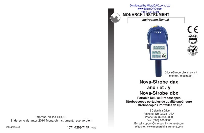
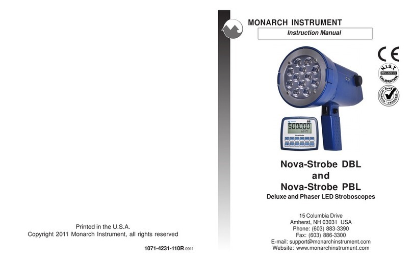
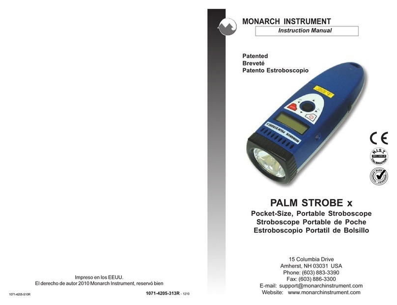
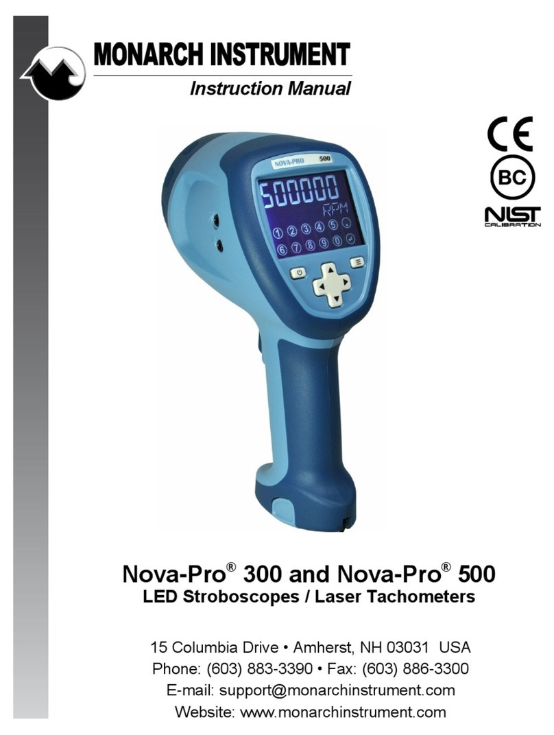
MONARCH INSTRUMENT Phaser-Strobe pbx User manual

Instruction Manual
Phaser-Strobe pbx
Portable Phase-Shiing Stroboscope
15 Columbia Drive
Amherst, NH 03031 USA
Phone: (603) 883-3390 • Fax: (603) 886-3300
E-mail: [email protected]
Website: www.monarchinstrument.com

SAFEGUARDS AND PRECAUTIONS
1. Read and follow all instrucons in this manual carefully, and retain this manual
for future reference.
2. Do not use this instrument in any manner inconsistent with these operang
instrucons or under any condions that exceed the environmental
specicaons stated.
3. Certain strobe frequencies can trigger epilepc seizures in those prone to that
type of aack.
4. Users should not stare directly at the light source.
5. Prolonged exposure to the light can cause headaches in some people.
6. Objects viewed with this product may appear to be staonary when in fact
they are moving at high speeds. Always keep a safe distance from moving
machinery and do no touch the target.
7. There are lethal voltages present inside this product. Refer to the secon on
Lamp Replacement before aempng to open this product.
8. Do not allow liquids or metallic objects to enter the venlaon holes on the
stroboscope as this may cause permanent damage and void the warranty.
9. Do not allow cables extending from unit to come into contact with rotang
machinery, as serious damage to the equipment, or severe personal injury or
death may occur as a result.
10. This instrument may not be safe for use in certain hazardous environments,
and serious personal injury or death could occur as a result of improper use.
Please refer to your facility’s safety program for proper precauons.
AC Stroboscopes that have three wire mains cable must have
the earth wire connected to a suitable Earth point.

In order to comply with EU Direcve 2012/19/EU on Waste Electrical
and Electronic Equipment (WEEE): This product may contain material
which could be hazardous to human health and the environment. DO NOT
DISPOSE of this product as unsorted municipal waste. This product needs to be
RECYCLED in accordance with local regulaons; contact your local authories for
more informaon. This product may be returnable to your distributor for recycling;
contact the distributor for details.
Monarch Instrument’s Limited Warranty applies.
See www.monarchinstrument.com for details.
Warranty Registraon and Extended Warranty Coverage informaon is available
online at www.monarchinstrument.com.
Monarch Instrument holds the following US trademarks and registraons, all rights
reserved: illumiNova®, Nova-Pro®, Nova-Strobe™, DataChart™, Track-It™.
11. The product contains Nickel Metal Hydride baeries which must be disposed
of in accordance with Federal, State, & Local Regulaons. Do not incinerate.
Baeries should be shipped to a reclamaon facility for recovery of the metal
and plasc components as the proper method of waste management. Contact
distributor for appropriate product return procedures.
12. This instrument is not user serviceable. For technical assistance, contact
the sales organizaon from which you purchased the product or Monarch
Instrument directly.

TABLE OF CONTENTS
1.0 OVERVIEW ..................................................................................... 1
1.1 Display Panel / Denion of Buons ......................................... 1
2.0 PREPARATION FOR USE ............................................................... 3
2.1 Power ........................................................................................ 3
2.2 Input / Output Connecons ........................................................ 3
3.0 MENU ............................................................................................. 5
4.0 OPERATION ................................................................................... 6
4.1 Internal Mode - Standard Strobe Operaon ............................... 6
4.2 Internal Mode - TACH Frequency Generator .............................. 9
4.3 External Input Mode .................................................................. 9
4.4 Tachometer Mode - External Input Required ............................. 10
4.5 External Delay Modes (Phase Shiing) ...................................... 10
4.6 Power Up Features .................................................................... 11
5.0 USING THE STROBOSCOPE TO MEASURE RPM ............................. 12
6.0 LIMITATIONS OF REMOTE OPTICAL SENSORS ................................ 14
7.0 LAMP REPLACEMENT AND FUSE .................................................. 14
7.1 Lamp Replacement ................................................................... 14
7.2 Fuse .......................................................................................... 16
8.0 BATTERY AND POWER SUPPLY SPECIFICS ................................. 17
8.1 Low Baery Indicaon ............................................................. 17
8.2 Charging the Baeries .............................................................. 18
8.3 External Power Supply/Charger ................................................ 18
8.4 Baery Disposal ....................................................................... 19
9.0 SPECIFICATIONS ......................................................................... 19
9.1 Compliance .............................................................................. 21
10.0 ACCESSORIES, SENSORS and REPLACEMENT PARTS ................. 22

1
1.0 OVERVIEW
The Phaser-Strobe pbx is an extremely sophiscated instrument with many
features, yet remains simple to operate. Select only the features you need.
1.1 Display Panel / Denion of Buons
The display panel consists of a backlighted liquid
crystal display with six numeric digits on top and
ve alphanumeric digits on the boom, which
indicate modes, ash rates, etc. (see Figure 1).
Addional informaon displayed include:
PHASE Indicates Phase Shi Delay Mode is acve
TIME Indicates Phase Shi Time Delay Mode is acve
AUTO Indicates Auto Phase Shiing Mode (Virtual RPM) is acve
ALT. Indicates alternate funcon of each buon (lower secon)
and knob will be used
TACH Tachometer Mode acve (strobe won’t ash)
LOCK Unused
EXT External Input Mode acve
On Target Indicator for Tachometer Mode and Remote
Sensor in External Mode
- - - - - Indicates input frequency exceeds the limit of the stroboscope
Baery indicaon (see 8.1 Low Baery Indicaon)
Figure 1 Display Panel

2
Below the display are six membrane buons which control the
operaon of the stroboscope.
Mulply Flash Rate by 2
ALT Funcon - starts menu (see secon 3.0)
Hold when powering up to show all segments, then rev # and
display test
Divide Flash Rate by 2
Hold when powering up to reset factory defaults
DISPLAY/TACH
Internal/External Mode: toggles display between RPM and RPS
External Phase or Time Delay Mode: cycles display through
RPM, RPS, Phase and Time
Auto Mode: cycles display through RPM, RPS, VRPM and VRPS
ALT Funcon—toggles Tach Mode (ashing) on/o
INPUT/MEMORY
Manually toggles between Internal and External Modes
ALT Funcon—Memory, reads and stores 9 preset ash rates
ALT FUNCTION
Acvates Alternate Funcon for buons (lower secon)
and knob
PHASE DELAY
Internal Mode: toggles between normal ash rate adjust and
“phase” delay adjust
External Input Mode: cycles through External only (no delay),
Phase, Time and Auto (VRPM)

3
The ALT FUNCTION buon toggles ALT. in the display. When ALT. is
displayed, the buons will perform their secondary funcon listed
in the lower secon of each buon. It also changes how the tuning
knob works.
2.0 PREPARATION FOR USE
The strobe may be handheld or mounted on a tripod or other user supplied
bracket using the ¼-20 UNC bushing at the base of the handle.
2.1 Power
The Phaser-Strobe pbx has internal rechargeable baeries and may
also be powered by an external AC power supply (PSC-pbxU). If using
the internal baeries, the unit should be charged before use (see
secon 8.2 Charging the Baeries). The actual operang me of the
stroboscope depends on the ash rate and duty cycle of operaon. The
strobe can also be run connuously from the AC mains with the power
supply supplied (see secon 8.3 External Power Supply/Charger).
2.2 Input / Output Connecons
The Phaser-Strobe pbx has input and output jacks on the le side
of the stroboscope. These can be used for external triggering or
synchronizaon (daisy chaining two or more strobes). These jacks
accept 1/8" (3.5 mm) phone plugs (input - stereo, output - mono). The
input and output are TTL compable. (See Figures 2 and 3 for connector
connecon detail.)

4
Figure 2 Input Connector Detail (Stereo plug)
Signal Input
+6V Out to
Sensor
+6V Out to
Sensor
Signal Input
Common
(GND)
Common
(GND)
Common
(GND)
Common
(GND)
Pulse Output
from Strobe
Pulse Output
from Strobe
Figure 3 Output Connector Detail (Mono plug)
The oponal ROS-P (Remote Opcal Sensor), MT-190P (Magnec), or
IRS-P (Infrared) sensors may also be used to trigger the unit.
NOTE: When using external sensors that are powered by the Phaser-
Strobe pbx, e.g. Remote Opcal Sensor (ROS-P), the sensor must be
plugged in before the stroboscope is turned on, or the remote sensor
may not be powered up.
The input jack (▲ poinng into socket) enables an external signal to
trigger the strobe. Inserng a plug into the input jack will automacally
put the strobe into the External Input Mode. The INPUT buon can be
used to toggle between External Input Mode and Internal Mode. When
the plug is removed, the strobe will be put back into the Internal Mode.
The polarity of the input pulse can be set in the MENU opons.

5
With no external input, the output jack (▼poinng away from socket)
provides a TTL compable pulse from the strobe’s internal oscillator. If
an external input is applied, the output pulse is in sync with the input
pulse. This output pulse may be used to trigger a second stroboscope
synchronously to illuminate larger areas. Many strobes can be daisy
chained. The output jack of one strobe is connected to the input jack
of the next strobe causing all the strobes to ash together and be
controlled by the rst strobe in the chain. The polarity of the output
pulse can be set in the MENU opons.
3.0 MENU
The strobe has a Menu which allows the user to select sengs such as
number of decimal places, backlight on or o, posive or negave edge
for input and output signal, and input blanking on or o.
To enter the MENU:
1. Press the ALT FUNCTION buon and then the MENU buon.
2. SETUP and the menu opon will be displayed.
3. Turn the tuning knob to cycle through the main menu opons.
4. Once the desired menu opon is displayed, press the MENU buon to
select it. Press any other buon to cancel.
5. Turn the tuning knob to edit the menu opon seng.
6. Press the MENU buon to save your changes. Press any other buon
to cancel.
7. Press any buon other than MENU to exit the Main Menu.
8. DONE will be displayed.
Below is a list of the menu items:
DECPT Decimal Point (none, 1 or 2)
BLITE Backlight (Yes=On or No=O)
INPUT Posive (pos) or Negave (neg) Edge for Input Signal
OUTPT Posive (pos) or Negave (neg) Edge for Output Signal
BLANK Input Blanking (Yes=On or No=O)

6
4.0 OPERATION
To turn on the stroboscope, depress and hold the trigger. The trigger may
be locked in posion using the side locking buon. To lock the stroboscope
on, depress the trigger as far as it will go and then press the locking buon.
Once the locking buon is set you may release the trigger and the trigger
will be held in place. To unlock the stroboscope, simply depress the trigger
and then release.
NOTE: Unit must power down completely (OFF will be displayed and then
disappear) before unit will power on again. This is normal operaon.
There are ve (5) operang modes for the Phaser-Strobe pbx. These are
Internal, External Input, External Phase Delay, External Time Delay, and
Auto (Virtual RPM). All but the Internal Mode require an external input
signal.
In the Internal Mode, the knob adjusts the ash rate. In the External Input
Mode, an external signal is used to trigger the ash and the knob has no
eect. The External Delay Modes (Phase, Time and Auto) enable the user
to vary the stopped moon image at any point in the cycle without having
to move the trigger source locaon.
4.1 Internal Mode - Standard Strobe Operaon
In the Internal Mode, the stroboscope generates its own signals and
funcons like a tunable stroboscope. The strobe is in the Internal Mode
when nothing is plugged into the input jack or when manually set using
the INPUT buon.

7
To change the ash rate:
With the power on, turn the knob counter clockwise to increase the
ash rate and clockwise to decrease it. The knob is velocity sensive.
Turn the knob slowly to have each click equal to 0.01 FPM. Turning the
knob more quickly will adjust the FPM by larger steps. When adjusng
ash rate, quickly turn the knob (or use the x2 or ÷2 buons) to coarsely
change the FPM. Then slowly turn the knob for ne adjustments.
NOTE: There are maximum and minimum values in each mode beyond
which you cannot adjust. If you are adjusng the rate and you reach a
value on which the next increment would exceed the maximum ash
rate, the display will not increment. The same is true if you try to
adjust the ash rate below the minimum ash rate.
To mulply or divide the current ash rate by 2:
In addion to the knob, there are two buons on the display panel
marked x2 and ÷2. These enables the user to instantly double or
halve the reading on the display to the maximum or minimum values
allowed. This feature is useful for checking harmonics in the internal
ashing mode.
Alternate Knob Funcon - Mulple by 2, 3, 4, 5, etc.
The tuning knob funcons dierently when ALT. is displayed. The
current ash rate is used as an adder. The knob will add (counter
clockwise) or subtract (clockwise) that inial ash rate for each click
the knob is turned. This in eect allows the user to mulply the inial
ash rate by 2, 3, 4, 5, etc., up to the maximum ash rate. This is very
helpful on fan blades. Using this feature, one can superimpose the
blades on top of each other and check for blade tracking, bent blades,
lead and lag tests, etc.

8
Example: A 3-bladed fan is spinning at 3600 RPM. The strobe is ashing
at 3600 FPM. Press the ALT FUNCTION buon to display ALT. Then
turn the knob counter clockwise 2 clicks. The strobe will now ash
at 10,800 FPM (eecvely 3600 mes 3). The fans blades will be all
superimposed on each other. One can now see if the blades are out of
alignment, bent, etc. by viewing the blades from the front or viewing
from the side edge of the blades.
To select a ash rate from a preset (memory) locaon:
1. Press the ALT FUNCTION buon and then the MEMORY buon;
READ will be displayed.
2. Turn the tuning knob to cycle through the preset ash rates.
3. Once the desired ash rate is displayed, press the MEMORY buon
to select it. Press any other buon to cancel; DONE will be displayed.
To select a current ash rate in a preset (memory) locaon:
1. Press the ALT FUNCTION buon and then the MEMORY buon;
READ will be displayed.
2. Do NOT turn the knob and press the MEMORY buon again; STORE
will be displayed.
3. Turn the tuning knob to cycle through the memory locaons.
4. Once the desired memory locaon is displayed, press the MEMORY
buon to store the current ash rate in that locaon. Press any
other buon to cancel. DONE will be displayed.
Internal Phase Delay/Jog:
Once the ash rate has been adjusted to give a stopped moon image,
the PHASE DELAY buon may be used with the knob to increase or
decrease the phase of the reference mark locaon. Use the PHASE
DELAY buon and knob to bring a reference mark, such as a keyway,
into your line of sight.

9
To adjust the Phase Delay:
1. Press the PHASE DELAY buon. PHASE will be displayed on the
boom line and the current ash rate will be displayed on the top
line.
2. Turn the tuning knob to adjust the locaon (phase) of the reference
mark.
3. Press the PHASE DELAY buon again to turn the Phase Delay mode
o.
4.2 Internal Mode - TACH Frequency Generator
In the Internal Mode, the strobe can be used as a frequency generator
(outpung TTL pulses) without having the strobe ash. The pulse
output will sll occur at the ash rate; the strobe is just not ashing.
To stop ashing:
Press the ALT FUNCTION buon and then the TACH buon. The TACH
icon will be displayed.
To start ashing again:
Press the ALT FUNCTION buon and then the TACH buon. The TACH
icon will go away and the strobe will start ashing again.
4.3 External Input Mode
In the External Input Mode, the user cannot make any ash rate
adjustments. The ash rate is a funcon of the input signal. This mode
is used to synchronize the ash to an external event (for example, from
an opcal sensor) to stop or freeze moon. The ash will be triggered
on the rising or falling edge (menu selectable) of the external input
pulse.
The strobe is in the External Input Mode whenever there is a plug in
the input jack. When the strobe is in the External Input Mode, EXT will
be displayed.

10
4.4 Tachometer Mode - External Input Required
When an external input is supplied to the unit and the strobe is put in
the Tachometer Mode, the unit will read the signal from the external
input (sensor) and display the reading on the LCD without ashing the
lamp. The strobe will not ash in the Tachometer Mode.
To enter the External Tachometer Mode:
1. Plug an external input into the unit.
2. Press the ALT FUNCTION buon and then the TACH buon. The
TACH icon will be displayed.
NOTE: If the external input signal exceeds the maximum ash rate,
the strobe will go into the Tachometer Mode automacally.
To exit the External Tachometer Mode:
1. Press the ALT FUNCTION buon and then the TACH buon. The
TACH icon will go away.
2. The unit will remain in the External Input Mode unless the INPUT
buon is pressed to change the mode.
4.5 External Delay Modes (Phase Shiing)
There are three External Delay Modes: Phase Delay, Time Delay, and
Auto (Virtual RPM). In the External Phase Delay Mode, the ash is
triggered 0.1 to 359.9 degrees aer each external signal pulse. The knob
sets the amount of delay in degrees. In the External Time Delay Mode,
the ash is triggered 0.01 to 1000 milliseconds aer each external
signal pulse. The knob sets the amount of delay in milliseconds. In the
Auto (Virtual RPM) Mode, the ash is triggered by increasing amounts
aer the external trigger pulse so that the image will appear to rotate
at a given (virtual) RPM or RPS. The knob sets this virtual RPM or RPS.

11
To enter one of the External Delay Modes:
1. Plug an external input into the unit.
2. Press the PHASE DELAY buon to cycle to the desired mode.
3. Use knob to adjust delay/angle (phase, me or virtual RPM).
To exit the External Delay Mode:
1. Press the PHASE DELAY buon to cycle back to External only.
2. The word PHASE or the TIME or AUTO icon will go away.
4.6 Power Up Features
When the strobe is powered up, it will remember the last sengs.
Press and hold the x2/MENU buon, then turn on the strobe by
depressing the trigger switch. This will turn on all the display segments
for two seconds or unl you release the buon. It will then show the
soware revision, “REV x.x” and then go through a display diagnosc.
Press and hold the ÷2 buon, then turn on the strobe by depressing
the trigger switch. This will restore the factory programmed presets.

12
5.0 USING THE STROBOSCOPE TO MEASURE RPM
The primary use for a stroboscope is to stop moon for diagnosc inspecon
purposes. However the stroboscope can be used to measure speed (in
RPM/RPS). In order to do this several factors need to be considered. First,
the object being measured should be visible for all 360° of rotaon (e.g.
The end of a sha). Second, the object should have some unique part on
it, like a bolt, keyway or imperfecon to use as a reference point. If the
object being viewed is perfectly symmetrical, then the user needs to mark
the object with a piece of tape or paint in a single locaon to be used as a
reference point. Look only at the reference point.
If the speed of rotaon is within the range of the stroboscope, start at the
highest ash rate and adjust the ash rate down. At some point you will
stop the moon with only a single reference point of the object in view.
Note that at a ash rate twice the actual speed of the image, you will see
two images (reference points). As you approach the correct speed, you
may see three, four or more images at harmonics of the actual speed. The
rst SINGLE image you see is the true speed. To conrm the true speed,
note the reading and adjust the stroboscope to exactly half this reading, or
just press the ÷2 buon. You should again see a single image (which may
be phase shied with respect to the rst image seen).
For example, when viewing a sha with a single keyway you will see one
staonary image of the keyway at the actual speed and at 1/2, 1/3, 1/4,
etc, of the actual speed. You will see 2 images of the keyway at 2 mes
the actual speed, 3 keyway at 3 mes, etc. The Flashes Per Minute (FPM)
equals the sha’s Revoluons Per Minute (RPM) at the highest ash rate
that gives only one staonary image of the keyway.

13
Stopped Image 1/4 mes 1/2 mes 1 me 2 mes 3 mes 4 mes
Flash Rate (FPM) 1250 2500 5000 10000 15000 20000
Example: Object Rotang at 5000 RPM
If the speed is outside the full scale range of the stroboscope (20,000
FPM), it can be measured using the method of harmonics and mulpoint
calculaon. Start at the highest ash rate and adjust the ash rate down.
You will encounter mulple images so be aware of these. Note the ash
rate of the rst SINGLE image you encounter, call this speed “A”. Connue
decreasing the ash rate unl you encounter a second SINGLE image. Note
this speed as “B”. Connue decreasing the speed unl you reach a third
SINGLE image at speed “C”.
For a two-point calculaon the actual speed is given by: RPM = AB/(A-B)
For a three-point calculaon: RPM = 2XY(X+Y)/(X-Y)2 where
X = (A-B) and
Y = (B-C)
If a Remote Opcal Sensor or Magnec Sensor is used to sense one pulse
per revoluon (External mode), the readout will display directly in RPM
(FPM) without any adjustment required.
In instances when you can shut down the device and install a piece of
reecve tape, then an opcal tachometer is easier to use for RPM
measurement. Stroboscopes must be used when you cannot shut down
the device. The human eye is not easily tricked into seeing a stopped
image by a stroboscope when the ash rate is slower than 300 FPM.
Therefore, stroboscopes are just about impossible to use below 300 FPM
for inspecon or to measure RPM.

14
6.0 LIMITATIONS OF REMOTE OPTICAL SENSORS
Remote Opcal Sensors have a limitaon when used with the Phaser-
Strobe pbx because they sense not only the reecve marker but the
strobe ash as well. If the ROS is posioned near the strobe, the light from
the strobe may cause the ROS to trigger the stroboscope at the wrong
me, especially when using a delayed ash mode. The Phaser-Strobe pbx
has an Input Blanking feature to allow it to ignore this false trigger.
Even with the Input Blanking, large delays cannot be obtained using an ROS
if the strobe’s ash is triggering the ROS. The duraon of the ROS pulse in
response to the strobe’s ash is about 0.5 milliseconds to 1.1 milliseconds
depending on the ash rate. This limits the largest delay possible because
the ash swamps the signal from the ROS, and consequently it will not
provide the pulse from the reecve marker. If large delays are desired,
reposion the ROS so it is away from the strobe’s ash or use a magnec
sensor.
The Input Blanking feature itself limits the maximum delay which is
detrimental to non-opcal sensors. It is possible to disable (or enable) the
blanking in the Phaser-Strobe pbx (see 3.0 Menu).
7.0 LAMP REPLACEMENT AND FUSE
7.1 Lamp Replacement
WARNING
Before aempng to remove the lamp, make sure the
stroboscope is turned o and any mains cord is removed from
the AC outlet. Allow the lamp to cool waing at least 5 minutes.
The stroboscope is designed to discharge the internal high voltages
within 30 seconds. However, cauon should be exercised when
replacing the lamp.

15
The lamp can be replaced by using just a pocket screwdriver. It is not
necessary to remove any screws to replace the lamp.
To change the lamp:
Push apart the two tabs on the side of the reector housing and
remove the lens using a small screwdriver to help pry one tab and
li the lens. Take care not to pry the tab any more than is necessary
to free the lens. The reector is held in place by the front lens and
will come loose, but it is not necessary to remove the reector.
Hold the lamp with a cloth between your forenger and thumb
and rock it back and forth gently while pulling out. Do not aempt
to rotate the lamp. The lamp is socketed and will come out easily
when pulled straight out.
WARNING
Do NOT touch the new lamp with bare ngers.
The lamps are polarized and must be put into the socket matching
polarity. Using a lint free cloth, match up the red dot on the plug
with the red dot on the socket and gently rock the lamp while
pushing it into place (see Figure 4). Make sure the lamp is in straight
and centered in the reector hole.
CAUTION
Do NOT allow the reector to contact the lamp.
1.
2.
3.

16
Red Dots
Notches
Figure 4 Lamp Replacement
Reinstall the reector and then posion the front lens in place
matching up the notches on the lens with the two small tabs on the
housing to prevent lens rotaon (see Figure 4). Push the tabs on the
front rim outward and press the lens into place.
7.2 Fuse
Under normal operang condions, the fuse within the stroboscope
should never blow. Examples of abnormal operang condions would
be foreign materials entering the strobe, such as water, pulp, ink, etc.
The Phaser-Strobe pbx has a replaceable fuse, which will reset once
condions are normal again.
4.
Table of contents
Other MONARCH INSTRUMENT Test Equipment manuals
MONARCH INSTRUMENT
MONARCH INSTRUMENT Nova-Pro UV365 User manual

MONARCH INSTRUMENT
MONARCH INSTRUMENT Nova-Strobe Use and care manual

MONARCH INSTRUMENT
MONARCH INSTRUMENT Nova-Pro Series User manual

MONARCH INSTRUMENT
MONARCH INSTRUMENT Nova-Pro 300 User manual

MONARCH INSTRUMENT
MONARCH INSTRUMENT PALM STROBE x User manual

MONARCH INSTRUMENT
MONARCH INSTRUMENT Nova-Strobe DBL User manual

MONARCH INSTRUMENT
MONARCH INSTRUMENT PALM STROBE x User manual

MONARCH INSTRUMENT
MONARCH INSTRUMENT Nova-Pro Ultra Violet UV365 User manual

MONARCH INSTRUMENT
MONARCH INSTRUMENT Nova-Strobe dax User manual
MONARCH INSTRUMENT
MONARCH INSTRUMENT Nova-Strobe BBL User manual