UNFOLDING
THE
MONTAGUE
BIFRAME
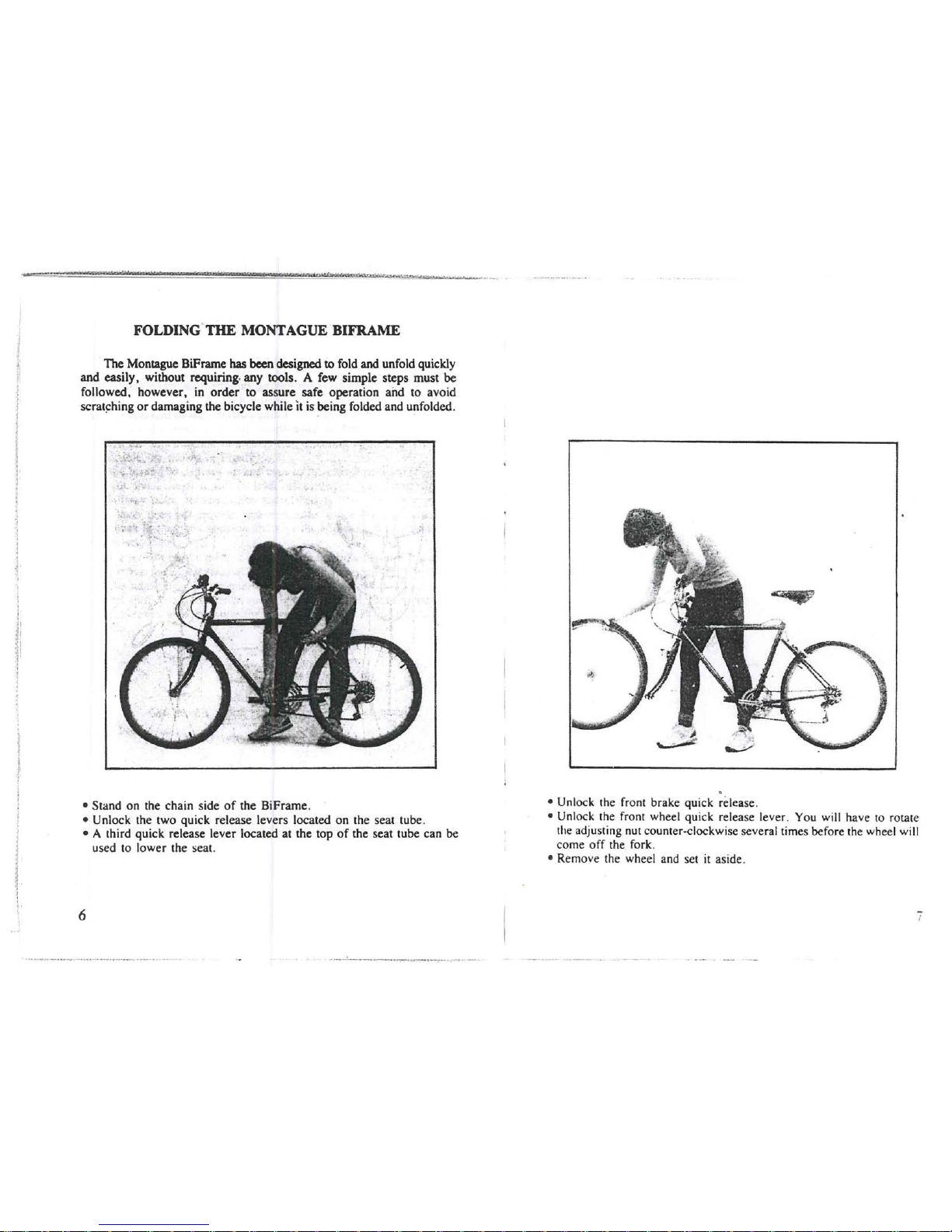
•
To
unfold the
BiFrame,
first loosen the seat
tube
quick release levers.
•Rotate the pedals so that the pedal
on
the chain side
of
the BiFrame
is
at the bottom
of
its swing pointed away from the seat.
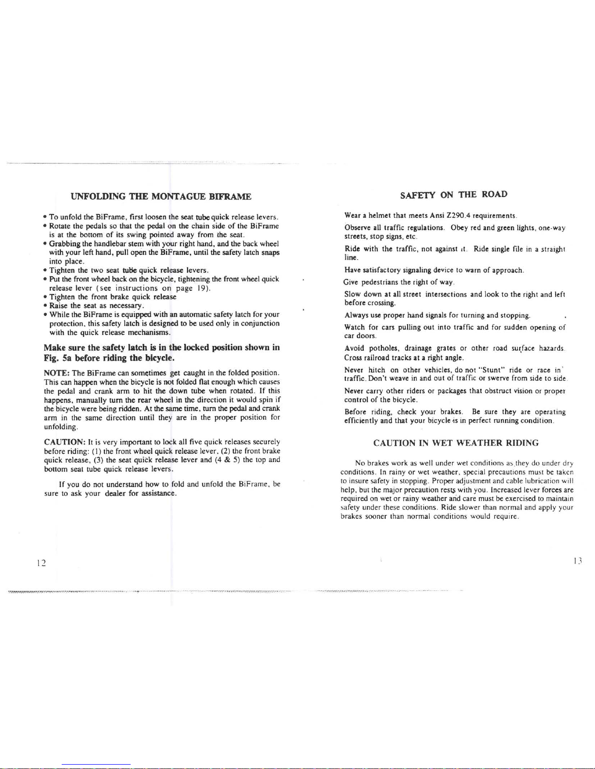
•
Grabbing
the handlebar stem with
your
right hand, and the back wheel
with
your
left hand, pull open the BiFrame, until the safety latch snaps
into place.
•Tighten the two seat tutie quick release levers.
•Put the front wheel back
on
the bicycle, tightening the front wheel quick
release lever
(see
instructions
on
page
19).
•Tighten the front brake quick release
•Raise
the
seat as necessary.
•While the
BiFrame
is equipped with
an
automatic safety latch for
your
protection. this safety latch is designed to
be
used only in conjunction
with the quick release mechanisms.
Make sure the safety latch
is
in the locked position shown
in
Fig. 5a before riding the bicycle.
NOTE:
The
BiFrame can sometimes get caught in the folded position.
This can happen when the bicycle is not folded flat enough which causes
the pedal and
crank
arm
to hit the
down
tube when rotated.
If
this
happens, manually turn
the
rear
wheel in the direction it would spin
if
the bicycle were being ridden. At the same time, turn the pedal and crank
arm
in
the same direction until they
are
in the
proper
position for
unfolding.
CAUTION:
It
is
very important to lock all five quick releases securely
before riding:
(I)
the front wheel quick relea'se lever. (2) the front brake
quick release, (3) the seat
quitk
release lever and (4 &5) the top and
bottom seat tube quick release levers.
If
you
do
not understand how to fold and unfold the BiFrame. be
sure to ask
your
dealer
for assistance.
I
:2
SAFETY ON
THE
ROAD
Wear ahelmet
that
meets Ansi
Z290.4
requirements.
Observe all traffic regulations. Obey red and green lights, one·way
streets, stop signs, etc.
Ride with
the
traffic, not against
It.
Ride single file
in
astraight
line.
Have satisfactory signaling device to warn
of
approach.
Give pedestrians the right
of
way.
Slow down at all street intersections and look
to
the right and left
before crossing.
Always use proper hand signals for turning and stopping.
Watch for cars pulling
out
into traffic and for sudden opening
of
car doors.
Avoid potholes, drainage grates or other road
su~face
hazards.
Cross railroad tracks at aright angle.
Never hitch on
other
vehicles, do
not
"Stunt"
ride or race in'
traffic.
Don't
weave
in
and
out
of
traffic or swerve from side to side.
Never carry
other
riders or packages that obstruct vision or proper
control
of
the bicycle.
Before riding, check your brakes.
Be
sure they are operating
efficiently and that your bicycle
-is
in
perfect running condition.
CAUTION
IN
WET
WEATHER
RIDING
No brakes work as well under wet conditions as.they do under dry
conditions.
In
rainy
or
wet weather. special precautions must
be
taken
to insure safety
in
stopping. Proper adjustment and cable lubrication will
help, but the major precaution
res~
with you. Increased lever forces are
required on wet
or
rainy weather arid care must be exercised
to
maintain
safety under these conditions. Ride slower than normal and apply your
brakes sooner than normal conditions would require.
-~
.......
;;:'"
.;~
...
~~~
..
-"
......
'
..
-.""
.-.'~'
.
--"
,.
....
---
~_.
~..._
..
-.
-_.-
13