MONTAGUE E36W36 Operating and maintenance manual

INSTRUCTIONAL
MANUAL
THE MONTAGUE COMPANY
1830 Stearman Avenue • P.O. BOX 4954 • HAYWARD,CA 94540-4954 •TEL: 510/785-8822 • FAX: 510/785-3342
GAS FIRED BROILERS
E36W36 EV136W36 EC36
E43W36 E236W36 EC45
E136W36 E243W36
Please read this manual completely before attempting
to install or operate this equipment! Notify carrier of
damage. Inspect all components immediately.
See page 4.
RETAIN THIS MANUAL FOR FUTURE REFERENCE.
DESTINATION COUNTRIES: IE, GB, RO
0359-10

2
IMPORTANT FOR YOUR SAFETY
THE INSTALLATION INSTRUCTIONS CONTAINED HEREIN ARE FOR THE USE OF
QUALIFIED INSTALLATION AND SERVICE PERSONNEL ONLY. INSTALLATION OR
SERVICE BY OTHER THAN QUALIFIED PERSONNEL MAY RESULT IN DAMAGE TO THE
UNIT AND/OR INJURY TO THE OPERATOR.
POST IN A PROMINENT LOCATION THE INSTRUCTIONS TO BE FOLLOWED IN THE EVENT
THE SMELL OF GAS IS DETECTED. THIS INFORMATION CAN BE OBTAINED FROM THE
LOCAL GAS SUPPLIER.
IN THE EVENT OF POWER FAILURE, DO NOT ATTEMPT TO OPERATE THIS DEVICE.
IF YOU SMELL GAS
1. TURN OFF THE APPLIANCE AT THE GAS INLET COCK AND OPEN ALL DOORS
AND WINDOWS.
2. DO NOT OPERATE ANY ELECTRICAL SWITCHES AND EXTINGUISH ALL NAKED
FLAMES.
3. CONTACT THE LOCAL GAS AUTHORITY IMMEDIATELY.
THE FOLLOWING INSTRUCTIONS SHOULD BE READ CAREFULLY AS THE
MANUFACTURER CANNOT BE HELD RESPONSIBLE FOR ANY DAMAGE TO
PROPERTY, PERSONS OR ANIMALS CAUSED BY INCORRECT INSTALLATION OR
OPERATION OF THE APPLIANCE.
IMPORTANT
IN THE EVENT A GAS ODOR IS DETECTED, SHUT DOWN UNITS AT MAIN SHUTOFF
VALVE AND CONTACT THE LOCAL GAS COMPANY OR SUPPLIER FOR SERVICE.
FOR YOUR SAFETY
DO NOT STORE OR USE GASOLINE OR OTHER FLAMMABLE VAPORS OR LIQUIDS IN
THE VICINITY OF THIS OR ANY OTHER APPLIANCE.
WARNING!
Improper installation, adjustment, alteration, service, or maintenance can cause
property damage, injury, or death. Read the INSTALLATION, OPERATING, AND
MAINTENANCE INSTRUCTIONS thoroughly before installing, servicing, or operating
this equipment.
SAVE THESE INSTRUCTIONS FOR FUTURE USE.

3
TABLE OF CONTENTS
IMPORTANT FOR YOUR SAFETY ………. 2
INTRODUCTION ………. 4
GENERAL ………. 4
MODELS ………. 4
DATA PLATE LOCATION ………. 4
SERIAL NUMBER LOCATION ………. 4
RECEIVING AND INSPECTING THE EQUIPMENT ………. 4
SPECIFICATIONS ………. 5
INSTALLATION ………. 6
STATUTORY REGULATIONS ………. 6
CLEARANCES ………. 6
VENTILATING HOOD ………. 6
VENTILATION AIR ………. 6
ASSEMBLY ………. 6
Legs ………. 6
Ceramic Radiants ………. 7
LOCATION ………. 7
SITING ………. 7
BATTERY ARRANGEMENT ………. 7
Setting in Place ………. 7
Floor Mounted Ranges ………. 8
GAS SUPPLY ………. 8
GAS CONNECTION ………. 8
GAS PRESSURE REGULATOR ………. 9
Adjustment Procedure ………. 10
PILOT INITIAL ADJUSTMENT ………. 11
BURNER ADJUSTMENT ………. 11
OPERATION ………. 14
GENERAL ………. 14
OPERATING CONTROLS ………. 14
Gas Control ………. 14
Lighting/Relighting Pilot and Main Burner ………. 14
Shutdown ………. 15
Grid Height Adjustment ………. 15
GENERAL MAINTENANCE ………. 17
GENERAL CLEANING ………. 17
Daily ………. 17
PAINTED SURFACES ………. 17
Exterior ………. 17
Interior ………. 17
STAINLESS STEEL SURFACES ………. 17
VENTILATION ………. 18
SERVICING ………. 18
SAFETY ………. 18
C36 & C45 EXPLODED VIEW ………. 19
C36 & C45 PARTS LIST ………. 20
36W36 & 43W36 EXPLODED VIEW ………. 21
36W36 & 43W36 PARTS LIST ………. 22
PARTS REMOVAL AND REPLACEMENT PROCEDURES ………. 23
COVERS AND PANELS ………. 23
Venturi Cover ………. 23
Control Panel Cover ………. 23
DRIP DEFLECTOR ………. 24
DRIP TRAY AND HORIZONTAL GREASE CONTAINER ………. 24
PILOT ASSEMBLY AND INJECTOR ………. 25
MAIN BURNER ………. 26
Burner Assembly, Orifice, and Venturi ………. 26
Burner Valve Removal/Replacement ………. 26
CARRIAGE POSITION HANDLE ………. 27
Black Ball Knob ………. 27
Chrome Sleeve ………. 27
Threaded Stud ………. 27
Gear and Tube Assembly ………. 27
Compression Spring ………. 28
Gear with Bracket ………. 28
SERVICE AND ADJUSTMENT PROCEDURES ………. 29
GAS PRESSURE REGULATOR ADJUSTMENT PROCEDURE ………. 29
PILOT BURNER CLEANING AND ADJUSTMENT PROCEDURE ………. 30
GAS TAPS ………. 30
CLEANING BURNER HEADS ………. 30
CLEANING BURNER VENTURI ………. 30
CARRIAGE POSITION HANDLE ADJUSTMENT PROCEDURE ………. 30
Handle Tension Adjustment ………. 30
CARRIAGE TENSION SPRING ADJUSTMENT PROCEDURE ………. 31
MISCELLANEOUS ………. 31
TROUBLESHOOTING CHART ………. 32
EC36 & E45 EXPLODED VIEW ………. 33
EC36 & E45 PARTS LIST ………. 34
E36W36 & E43W36 EXPLODED VIEW ………. 36
E36W36 & E43W36 PARTS LIST ………. 38

4
GENERAL
The gas broilers covered in this manual are
manufactured for use with the type of gas indicated
on the nameplate. Some models include a cabinet,
conventional oven or convection oven. Ovens are
covered in separate manuals. This manual only
covers the broiler.
Montague gas broilers are produced with the best
possible material and workmanship. Proper
installation is essential for safe, efficient, trouble-
free operation.
MODELS
Note: A suffix of ―SHB‖ designates searing plate
option.
DATA PLATE LOCATION
The Data Plate is located on the front of the unit,
or inside the oven burner.
SERIAL NUMBER LOCATION
Always have the serial number of your unit availa-
ble when calling for parts or service. The serial
number is on the nameplate that also includes the
model number. A typical identification plate is
shown in Figure 1.
* ―W‖ may be replaced with ―C‖ indicating no warm-
ing oven. ―36‖ may be replaced with ―45‖, indicating
a 45‖ broiler.
Figure 1. Typical Nameplate
RECEIVING AND INSPECTING
THE EQUIPMENT
Care should be taken during unloading so the
equipment is not damaged while being moved
into the building.
1. Visually inspect the exterior of the package and
skid or container. Any damage should be noted and
reported to the delivering carrier immediately.
2. If damaged, open and inspect the contents with
the carrier.
3. In the event that the exterior is not damaged, yet
upon opening, there is concealed damage to the
equipment, notify the carrier. Notification should be
made verbally as well as in written form.
4. Request an inspection by the shipping company
of the damaged equipment. This should be done
within 10 days from receipt of the equipment.
5. Freight carriers can supply the necessary
damage forms upon request.
6. Retain all shipping materials until an inspection
has been made or waived.
INTRODUCTION
MODEL CONSISTS OF
E36W36 Cabinet Base Broiler with
Warming Oven
E43W36 Cabinet Base Broiler with
Warming Oven
E136W36* Broiler with Conventional
Oven and Warming Oven
EV136W36* Broiler with Convection
Oven
E236W36 Double Broiler
E243W36 Double Broiler
EC36 Broiler Only
EC45 Broiler Only
MODEL:
SERIAL NO.:
HEAT INPUT: kW
CATEGORY:
SUPPLY PRESSURE: mbar
GAS: SET PRESS: mbar
ELECTRICAL
V Hz Ph W
COUNTRY:
P.I.N:
GAS CATERING EQUIPMENT
SALAMANDER– TYPE A
THE MONTAGUE COMPANY
HAYWARD, CALIFORNIA USA
0359-10

5
SPECIFICATIONS
Table A: Heat Input
Table B: Setting Pressure/Injector Size
Manifold Pressure Orifices
G20: 15 mbar Fixed for specified gas type
G31: 25 mbar G20: 2.95mm (#32 DMS)
G30: 25 mbar G31: 1.99mm (#47 DMS)
Gas Inlet Size:
3/4‖ BSP at lower left rear
(all models)
NOTE: The pressure must be measured at the pressure test nipple located at the
manifold pipe with the burner lit.
MODEL No. Burners
(broiler only)
G20 kW G31 kW Total kW
E36W36 212.3 ea. 12.3 ea. 4.6
E43W36 312.3 ea. 12.3 ea. 36.9
E136W36 212.3 ea. 12.3 ea. 36.3
EV136W36 212.3 ea. 12.3 ea. 36.3
E236W36 412.3 ea. 12.3 ea. 49.2
E243W36 612.3 ea. 12.3 ea. 73.8
EC36 212.3 ea. 12.3 ea. 24.6
EC45 312.3 ea. 12.3 ea. 36.9
MODEL G20mm G30mm G31mm PILOT FLAME
LENGTH mm
E36W36 25 32 32 12.5
E43W36 25 32 32 12.5
E136W36 25 32 32 12.5
EV136W36 25 32 32 12.5
E236W36 25 32 32 12.5
E243W36 25 32 32 12.5
EC36 25 32 32 12.5
EC45 25 32 32 12.5

6
INSTALLATION
CAUTION: Provision must be made to
assure adequate air supply to unit for
proper burner operation.
STATUTORY REGULATIONS
The installation of this appliance must be
carried out by a competent person in accord-
ance with the relevant regulations, standards,
codes of practice, and the related publications
of the country of destination.
CLEARANCES
The following are minimum clearances from
combustible and noncombustible materials.
With 152mm legs: Suitable for installation on
combustible floors.
Without legs: For use with special insulated
base on noncombustible floors only.
VENTILATING HOOD
The broiler(s) must be installed under a proper-
ly designed ventilating hood. The hood should
extend at least 152 mm beyond all sides of the
unit. The hood should be connected to an
adequate mechanical exhaust system.
VENTILATION AIR
The following notes are intended to give
general guidance. For detailed recommenda-
tions, refer to the applicable code(s) in the
country of destination.
NOTE 1: The room containing the appliance is
required to have a permanent air vent. The
minimum effective area of the vent is related to
the maximum rated hear input of the appliance
and shall be 4.5 cm² per kW in excess of 7kW.
NOTE 2: Air vents should be of such a size to
compensate for the effects of any extract fan in
the premises.
It is also necessary that sufficient room air
ingress be allowed to compensate for the
amount of air removed by the ventilating
system. Otherwise, a subnormal atmospheric
pressure will occur which may interfere with
burner performance or may extinguish the pilot
flame. In case of unsatisfactory broiler
performance, check with the exhaust fan in the
―OFF‖ position.
This appliance is to be installed with
sufficient ventilation to prevent the occurrence
of unacceptable concentrations of substances
harmful to health in the room in which it is
installed.
ASSEMBLY
Uncrate broiler as near to final location as
possible. For easier and lighter handling of
broiler, remove grids, grid frame, drip tray and
grease container. Remove all packing materials
and accessories from broiler interior.
Legs
Some broilers are mounted on legs.
1. Screws the legs into the modular stand.
2. Tightly screw the complete leg assembly
into the mounting holes in the bottom of the
broiler at each corner. If the unit is intended
for curb installation, no legs are provided.
The curb must be noncombustible material.
Location Combustible
Construction
Noncombustible
Construction
Back Wall 152 mm 0 mm
Left Side 152 mm 0 mm
Right Side 152 mm 0 mm

7
Ceramic Radiants
Ceramic radiants, Figure 2, are located on
each side of the burners. Ceramic end pieces
are installed at both ends of each burner
assembly. Five (5) ceramic radiants are
installed on each side of the burner with the
pointed side facing down and the side holes
facing up, Figure 3.
Figure 2. Ceramic Radiants Positioning
Figure 3. Ceramic Radiants
1. Insert ceramic end pieces at front and rear
of the burner frame. Four (4) are required for
each burner.
2. Tilt ceramic radiants sideways to clear
burner and frame assembly, then lower
radiant into position with one flange resting
on burner ledge and one flange resting on
frame edge.
3. Install the remaining ceramic radiants so
that five (5) ceramic radiants are located on
each side of the burner.
LOCATION
Adequate clearance for service and proper
operation must be provided at the front, top,
sides, and back. The combustion air openings
are provided in the front of the unit and must
not be obstructed.
SITING
The floor on which the range is to be sited must
be capable of adequately supporting the weight
of the appliance and any ancillary equipment.
Once in position, check that the unit is level,
both front to back and side to side. Adjust if
necessary, using the adjusting foot on each
leg.
BATTERY ARRANGEMENT
Carefully remove range from crate. Burner tie
wires and other packing materials must be
removed from the unit. On stainless steel units,
the protective material covering the stainless
steel must be removed immediately after unit is
installed.
Setting in Place
Model Nos. E36W36, E43W36, E136W36 and
EV136W36. (―W‖ may be replaced with ―C‖ in-
dicating no warming oven. ―36‖ may be re-
placed with ―45‖ indicating a 45‖ broiler.)

8
All fixed (non-mobile) appliances MUST be fitted
with a manual gas cook upstream of the appli-
ance to provide a means of isolation for servicing
and cleaning. A union or similar means of discon-
nection must be provided between the gas cook
and the appliance.
A manually operable valve must be fitted to the
gas supply to the kitchen to enable it to be isolat-
ed in an emergency. Wherever practical, this shall
be located either outside the kitchen or near an
exit in a readily accessible position.
Where it is not practical to do this, an automatic
isolation valve system shall be fitted which can be
operated from a readily accessible position near
the exit.
At locations where the manual isolation valve is
fitted or the automatic system can be reset, a
notice MUST be fitted, stating:
―ALL DOWNSTREAM BURNER AND PILOT
VALVES MUST BE TURNED OFF PRIOR TO
ATTEMPTING TO RESTORE THE SUPPLY.
AFTER EXTENDED SHUT OFF, PURGE
BEFORE RESTORING GAS.‖
GAS CONNECTION
Before connecting the broiler(s) to the gas supply
line, be sure that all new piping has been cleaned
and purged to prevent any foreign matter from
being carried into the controls by the gas. In some
cases, filters or drops are recommended. A
separate gas shutoff valve must be installed
upstream from the gas pressure regulator
adjacent to the broiler and located in an accessi-
ble area.
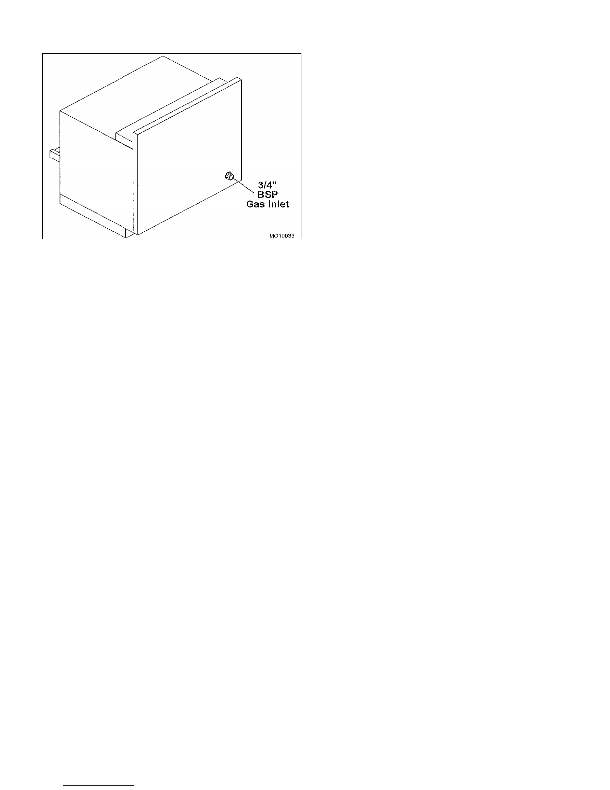
It is important that adequately sized piping be run
directly to the point of connection at the broiler
with as few elbows and tees as possible. Consult
your local gas company for proper piping size and
gas pressure. Each broiler has a 3/4" NPT
manifold input located at the lower left rear of the
broiler, Figure 4. On dual broilers, each broiler
must have a separate regulator.
NOTE: Pipe joint compound or thread sealant
that is used should be resistant to action of
liquefied petroleum gases.
Floor Mounted Ranges
1. Place the first unit in the exact position it will
occupy in the battery.
2. Using a carpenter’s level, level the unit front-
to-rear and side-to-side. AN UNLEVELED UNIT
WILL ADVERSELY AFFECT PERFORMANCE.
Adjust as follows:
FLOOR INSTALLATION ON LEGS: Level by
turning foot on leg.
CURB INSTALLATION: Place shim under the low
side. This operation is important since variations
in floors and curbs are common. Unless units are
level, aligning the gas supply manifold will be
difficult and the units will not fit together tightly.
3. Remove the valve panel from the broiler.
4. Move the next unit into position.
5. Engage union nut on manifold with male fitting
on next unit and draw up union nut hand tight. Be
sure appliances meet together both front and rear.
If manifolds do not align, then units are not level.
In extreme cases, it may be necessary to loosen
manifold bolts and adjust.
6. Continue leveling and connecting gas supply
manifolds together until all appliances in battery
are connected.
7. Tighten manifold gas union. Use backup
wrench to prevent manifold from rotating.
FAILURE TO DO THIS MAY RESULT IN
DAMAGE TO THE PILOTS AND GAS VALVES.
GAS SUPPLY
The local gas region should be consulted at the
installation planning stage in order to establish the
availability of an adequate supply of gas and to
ensure that the meter is adequate for the required
flow rate. The pipe work from the meter to the
appliances must be of appropriate size. Where a
number of appliances are installed in a battery, no
more than five should be served by any one
supply pipe.

9
Figure 4. Gas Inlet
Install the gas pressure regulator with gas
flowing as indicated by the arrow on the regula-
tor. The arrow must be pointing in toward the
unit. Use pipe compound or thread sealant and
carefully thread regulator to pipe so that there is
no cross threading, etc., which could cause leak-
age.
1. Apply wrench only to the flat areas around the
pipe tapping at the end being threaded to the
pipe to avoid possible damage to the regulator
body which could result in leakage.
2. Connect the gas supply line from the service
gas shutoff valve to the inlet side of the gas
pressure regulator using 3/4" pipe. Avoid kinks
or sharp bends that could restrict gas flow.
NOTE: If flexible or semi-flexible connectors
are used, a CE listed flexible connector
with an I.D. equal to 3/4" pipe must be used.
WARNING!
DO NOT USE A DOMESTIC TYPE
FLEXIBLE GAS CONNECTOR.
3. Turn gas shutoff valve on and carefully check
for gas leaks immediately. Do this before
attempting to operate the broiler.
WARNING!
Test all pipe joints for leaks before operating
broiler. This includes all gas connections
that may have loosened during shipment.
Use a rich soap solution (or other accepted
leak tester) around all pipe connections and
all other joints. Do not use an open flame.
Absolutely no leakage should occur, other-
wise there is a danger of fire or explosion
depending upon conditions. Do not use unit
leakage is detected.
After piping has been checked for leaks, all pip-
ing receiving gas should be fully purged to re-
move air.
GAS PRESSURE REGULATOR
WARNING!
THE BROILER(S) IS/ARE DESIGNED FOR
USE WITH A GAS PRESSURE REGULATOR.
THE REGULATOR(S) SUPPLIED WITH THIS
UNIT MUST BE USED.
FOR G20 GAS: This gas pressure regulator is
factory adjusted for 15 mbar manifold pressure.
The rated inlet pressure to the regulator is 3.45
kPa.
FOR G31 and G30 GAS: This gas pressure
regulator is factory adjusted for 25 mbar mani-
fold pressure. The rated inlet pressure to the
regulator is 3.45 kPa.
The broiler is equipped with fixed orifices for use
with a manifold pressure of 15 mbar for G20 gas
and 25 mbar for G31 and G30 gas.
Position the gas pressure regulator outside the
broiler as near to the unit as possible.
CAUTION: The gas pressure regulator must
be located out of the heat zone to prevent
damage to the regulator.
The whole of the gas installation, including the
meter, should be inspected, purged, and tested
for soundness in accordance with the codes of
the country of destination.

10
Adjustment Procedure
WARNING!
DO NOT ALLOW UNTRAINED PERSONNEL
TO MAINTAIN OR SERVICE THE GAS
PRESSURE REGULATOR.
1. Before adjusting the regulator, check the
incoming gas line pressure into the regulator.
Incoming pressure must be 20 mbar for G20
gas, 37 mbar for G31 gas, or 30 mbar for G30
gas.
2. If incoming pressure is not correct, have the
gas source checked and adjusted.
3. Make sure that the regulator is mounted in
the horizontal position with the arrow pointing
in the direction of the gas flow. SEE PAGE 14,
LIGHTING/RELIGHTING PILOT AND
BURNER.
4. Remove the main burner control valve
knobs,
Figure 5.
Figure 5. Control Valve Knobs
5. Remove the control valve panel by
removing two screws.
6. Connect a manometer to the pressure tap
provided on the broiler unit gas piping
manifold, Figure 6. Turn all gas taps to the full
―O‖ position.
7. Check the manometer reading. The
reading must be 15 mbar for G20 gas, 25 mbar
for G31 gas, or 25 mbar for G30 gas, per Table
B on PAGE 5.
8. If incoming line pressure is not correct,
adjust the regulator. Remove the seal cap
on the top of the regulator.
9. Insert a blade-type screwdriver into the top
hole of the regulator.
10. Turn the adjustment screw clockwise to
increase the pressure, or counter clockwise
to decrease the pressure.
While watching the manometer, turn the
adjustment screw to set proper regulator outlet
pressure to the manifold.
Figure 6. Gas Pressure Tap

11
PILOT INITIAL ADJUSTMENT
Each burner has a separate pilot burner. The
pilot flame is adjusted through access holes in
the valve control panel, Figure 7. Pilot access
is through the broiler opening.
1. Turn the main gas shut off valve to the ON
position.
2. Light each pilot.
3. Ensure that each pilot burner has a steady
blue flame, Figure 7, per Table C on PAGE
5.
4. The pilot flame should envelop the tip of the
thermocouple. The pilot flame can be
viewed up through the opening of the broiler
compartment.
Figure 7. Pilot Burner
Replace the control valve panel and the main
control valve handles.
BURNER ADJUSTMENT
The efficiency of the broiler depends on a
delicate balance between the supply of air and
the volume of gas at each main burner
resulting in complete combustion. Whenever
this balance is disturbed, poor operating
characteristics occur. An air shutter, Figure 8,
on the front of each main burner controls the
air supply.
NOTE: Pilots should be lit, SEE PAGE 12,
before adjusting the main burners.
1. Lift off the venturi cover to access the air
shutter for each main burner.
2. Turn on the main burner control valve for
the main burner to be adjusted by rotating
the main burner control valve fully counter-
clockwise to the ―O‖ position.
3. Increase the air shutter openings until the
flame on the burner begins to ―lift‖. Then
close the shutter until flame no longer
floats, and lock in place. A yellow streaming
flame indicates insufficient air. Correct this
condition by increasing air shutter opening.
The correct setting is shown on Table C on
PAGE 5.
Figure 8. Main Burner Air Shutter
4. After all main burners are properly adjusted,
reinstall the venturi cover.
5. Turn all main burner control valves fully
clockwise to the ―O‖ position to turn the
main burner off.

12
OVEN MINIMUM FLAME SETTING
This is the flame that must be maintained on the burner when the oven has come up to the
temperature set on the dial. Enough gas must be bypassed by the control to keep the entire burner
lit. The thermostat regulates the flame from high to low in accordance with the oven temperature
and will automatically turn down to this minimum flame when the temperature set on the dial is
attained in the oven.
1. Light the oven, set thermostat to 100°C and allow 5 minutes for the oven temperature to
stabilize.
2. After oven temperature rises and remains constant, turn dial back to low. This closes the main
valve and permits only the bypass gas to the burner.
3. Remove dial.
4. With a screwdriver, turn the bypass flame adjustor screw counterclockwise to increase the
bypass flame or clockwise to decrease it until the flame over the entire burner is approximately
4mm high. Replace dial.
P/N 01061-8

13
THERMOSTAT CALIBRATION CHECK
The calibration of this thermostat should not be changed until considerable experience with cooking
results has definitely proved that the thermostat is not maintaining the proper temperature. The
recalibration should not be made until the bypass (minimum burner) flame has been properly
adjusted.
If re-calibration becomes necessary, the following procedure should be followed:
1. Place the thermocouple of test instrument or thermometer in the middle of the oven.
2. Light the main burner.
3. Turn dial to between the ―180‖ and the ―200‖ position (190).
4. Allow the oven to heat until the flames cut down to bypass. After sufficient time, check
temperature. If the temperature does not read within 10 degrees of the dial setting, recalibrate
as follows:
A. Pull dial straight off without turning.
B. Hold calibration plate and loosen the two calibration lock screws until the plate can be
moved independently of the control.
C. Turn calibration plate so that the instrument or thermometer reading is in line with the
indicator mark. Hold plate and tighten screws firmly. Turn the calibration plate counter
clockwise if the test reading is higher than the dial setting. Replace dial.
NOTE: If the above adjustment is prevented by the two loosened calibration lock screws `
being in contact with the ends of the screw clearance slots in the calibration plate,
remove the screws and after turning the calibration plate to the proper location,
reassemble screws in the other tapped holes designed for them.
OVEN
A. Light pilot in accordance with the User’s Instructions.
B. Check that the length of the pilot flame is correct per table C.
All pilot flames should envelop the tip of the thermocouple. The pilot flame can be viewed through
the opening in the front of the burner compartment panel.
Replace the burner access panel.
Hand the User’s Instructions to the user or purchaser for retention and instruct them in the efficient
and safe operation of the appliance.
Tell the user of the location of the gas isolation cock for use in an emergency.
Leave this Installation and Operation Instruction Manual with the user or purchaser.

14
GENERAL
This appliance has been classified as
commercial cooking equipment and must be
operated by qualified and/or professional
operating personnel.
WARNING!
The broiler and its parts are hot. Use care
when operating or servicing the unit.
CAUTION:
Do not obstruct the flow of combustion and
ventilation air to the broiler. Keep appliance
area free and clear of combustibles.
OPERATING CONTROLS
WARNING!
IN THE EVENT GAS ODOR IS DETECTED,
SHUT DOWN UNITS AT MAIN GAS
SHUTOFF VALVE AND CONTACT THE
LOCAL GAS COMPANY OR GAS
SUPPLIER FOR SERVICE.
The following controls are used for operation of
the broiler, Figure 9.
Figure 9. Operating Controls.
BURNER CONTROL: Used to turn the main
burner and pilot gas on or off. One control for
each burner.
GRID HEIGHT: The grid is set to the desired
cooking height by depressing the ball and
adjusting the lever up or down.
Gas Control
Lighting/Relighting Pilot and Main Burner
1. Turn burner valve handle to off position and
wait five (5) minutes.
2. Push in the tap and turn it counter-
clockwise to the ignition position.
3. Holding the tap fully in, light the pilot with a
match or taper.
4. When the pilot is lit, continue to hold the tap
in for 20 seconds, then release it. If the pilot
goes out, wait for five (5) minutes, then
repeat from step 1.
5. When the pilot is established, push the tap
in again and turn it counter-clockwise to the
full flame position, thus lighting the main
burner.
6. If pilot becomes extinguished, turn main
burner valve to the off position (fully
counterclockwise) and wait five (5) minutes
before relighting.
OPERATION

15
Shutdown
1. Standby: To turn off, rotate main burner
valve handles clockwise to the ignition
position.
2. Complete: To shut the burner and pilot off,
turn the dial to the ―●‖ symbol and the
safety device will disengage within 60
seconds.
PREHEAT TIME— Allow at least five (5)
minutes after turning the broiler on from cold,
before loading the broiler with food to be
cooked.
Check the grease container and drain frequently
during heavy use to prevent overflow.
Grid Height Adjustment
Depress black ball and move lever up or down
to desired cooking height, Figure 9.

16
OVENS
The temperature is automatically controlled by the thermostat so that satisfactory cooking can be
repeated. For the best performance, the following instruction should be followed:
GRID SHELVES—There are three shelf positions. The shelf position is governed by the size of
the product to be cooked. Always push the shelf back into the oven until it stops by making
contact with the rear of the oven.
TRAY SIZE—A cake tray may be used on each shelf, Single trays or dishes must not be allowed
to overhang the shelf in any direction, since this will adversely affect the heat circulation.
PREHEAT TIME—Allow at least 30 minutes after turning the oven on from cold, with the thermo-
stat set at the desired temperature before loading the oven with food to be cooked. Put the food in
quickly and close the door.
LIGHTING THE OVEN
To light the oven:
1. Push in the main oven/pilot tap and turn it counter-clockwise to the ignition position.
2. Holding the tap in fully, depress the ignitor button and observe that the pilot lights. If it does
not, repeatedly depress the ignitor button until it does.
3. When the pilot is lit, continue to hold the tap fully in for 20 seconds, then release it. If the pilot
goes out, wait for five (5) minutes then repeat from step 1.
4. When the pilot is established, push the tap again and turn it counter-clockwise to the full flame
position ―260°C‖. Then the set thermostat to the desired temperature.
5. To shut the burner off, turn the dial to the ―●‖ position and the safety device will disengage
within 60 seconds.

17
GENERAL CLEANING
WARNING!
THE BROILER AND ITS PARTS ARE HOT.
USE CARE WHEN OPERATING, CLEANING
OR SERVICING THE UNIT.
Lint and grease suspended in the air tend to
collect in passages. Therefore, air openings,
flueways, and primary air openings, etc.,
should be periodically cleaned to prevent
clogging. The entire broiler should be given a
periodic cleaning.
Daily
Remove grid racks, drip deflector (below grid
rack), drip tray, and grease container.
Thoroughly wash with mild detergent or soap.
Excessive grease buildup may be removed by
using a mildly abrasive cleaner.
Figure 11. Items to be Cleaned Daily.
PAINTED SURFACES
Exterior
Allow the broiler to cool down before cleaning
exterior surfaces. Painted surface should be
cleaned using a mild soap and warm water
solution on a sponge or soft cloth.
Interior
Clean interior using a mildly abrasive cleanser
with a damp cloth or nylon cleaning pad.
STAINLESS STEEL SURFACES
To remove dirt, grease or product residue from
stainless steel, use ordinary soap and water
(with or without detergent) applied with a
sponge or cloth. Dry thoroughly with a clean
cloth.
To remove grease and food splatter, or
condensed vapors that have baked on the
equipment, apply cleanser to a damp cloth or
sponge and rub cleanser on the metal in the
direction of the polishing lines on the metal.
Rubbing cleanser as gently as possible in the
direction of the polished lines will not mar the
finish of the stainless steel. NEVER RUB WITH
A CIRCULAR MOTION.
Soil and burnt deposits which do not respond to
the above procedure can usually be removed
by rubbing the surface with SCOTCH-BRITE
scouring pads or STAINLESS scouring pads.
DO NOT USE ORDINARY STEEL WOOL as
any particles left on the surface will rust and
further spoil the appearance of the finish.
NEVER USE A WIRE BRUSH, STEEL
SCOURING PADS (EXCEPT STAINLESS),
SCRAPER, FILE OR OTHER STEEL TOOLS.
Surfaces which are marred collect dirt more
rapidly and become more difficult to clean.
Marring also increases the possibility of
corrosive attack.
GENERAL MAINTENANCE

18
To remove heat tint:
Darkened areas sometimes appear on
stainless steel surfaces where the area has
been subjected to excessive heat. These
darkened areas are caused by thickening of the
protective surface of the stainless steel and are
not harmful. Heat tint can normally be removed
by the procedures described above. Heat tint
which does not respond to this procedure calls
for a vigorous scouring in the direction of the
polish lines, using SCOTCH-BRITE scouring
pads or a STAINLESS scouring pad in combi-
nation with a powdered cleanser. Heat tint
action may be lessened by not applying or by
reducing heat to equipment during slack
periods.
VENTILATION
The area in which the appliance is installed
must be adequately ventilated to provide air for
combustion, removal of products of combustion
and removal of steam, etc. The use of a
mechanical extract system should be
considered.
SERVICING
To ensure efficient and safe operation of the
appliance, it is recommended that servicing is
carried out at regular intervals, the frequency of
which will vary depending on the installation
conditions and usage (usually once per year is
adequate).
Servicing must be carried out by competent
persons in accordance with the law.
SAFETY
It is essential that the instructions in this booklet
are strictly followed for the safe and economical
operation of the equipment. If it is known or
suspected that a fault exists on the appliance,
then it must not be used until the fault has been
rectified by a competent person.
WARNING!
All personnel in the workplace who may be
subject to any exposure of carbon monox-
ide must be warned of such possible
exposure. This warning should be
conveyed in a manner so that it is clearly
understood by the employee, and the
employee should be asked if in fact he or
she understands the correct method of
operation of the equipment and that a risk
of exposure exists if the equipment is
operated improperly.
SERVICERS AND NECESSARY
REPLACEMENT PARTS CAN BE OBTAINED
BY CONTACTING:
IMPERIAL CATERING
ELITE HOUSE
CASTLE BUSINESS PARK
PAVILION WAY
LOUGHBOROUGH LE11 5GW
TEL: 01509 260 150
FAX: 01509 260 151

19
C36 & C45 EXPLODED VIEW

20
C36
236W36
C45
243W36
12033-82033-8KNOB, BLACK BALL
23504-13504-1HANDLE, SLEEVE
31600-41600-4GRID IRON, RIGHT
4N/A 1602-0GRID IRON, CENTER
51601-21601-2GRID IRON, LEFT
643476-043476-0HANDLE, VALVE w/o RING
711611-411611-4CERAMIC, LARGE
7A 28387-828387-8
CERAMIC KIT (10 ea. 11611-4 Large
Ceramics; 4 ea. 11614-9 Ceramic
insulators)
811614-911614-9INSULATOR, CERAMIC
PART NUMBERS
ITEM DESCRIPTION
Other manuals for E36W36
1
This manual suits for next models
7
Table of contents
Other MONTAGUE Broiler manuals
Popular Broiler manuals by other brands

Blue Star
Blue Star Infra-Red Salamander Broiler Installation & operating instructions

Southbend
Southbend 234R owner's manual

Duke
Duke FBB-EC-208 Installation and operation manual

Blue Flame
Blue Flame BFRB-24 Installation & operation manual

Globe
Globe Chefmate C24CB-SR instruction manual

ITW Food Equipment Group
ITW Food Equipment Group SCB25 Installation and operation manual