ENGLISH
14
4
3
DangerProhibitedNecessity
1
2
European Safety
Certication
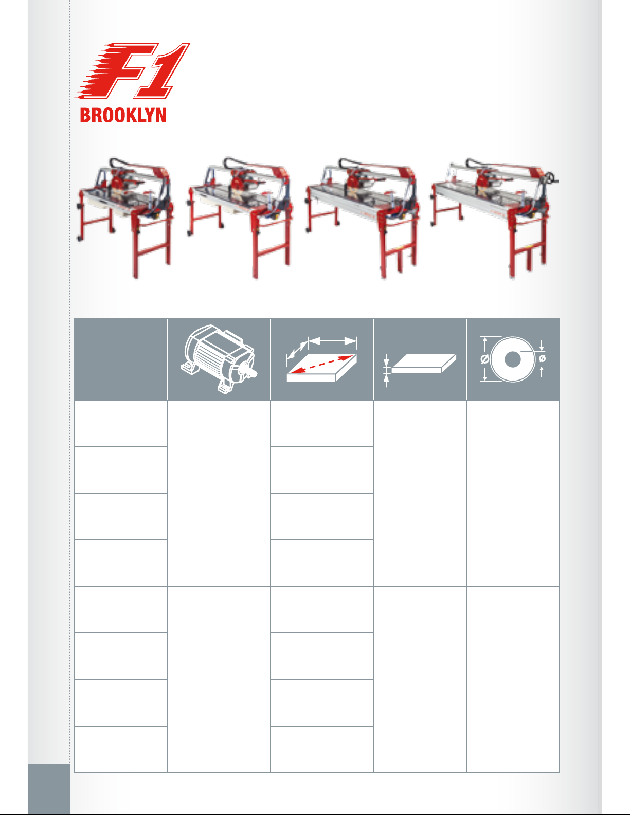
Diameter and bore
of diamond disk
Weight
ModelRAEE provisionsProhibitions
Read the instructions
Max RPMRegistration numberYear of production
Personal protective
equipment
Manufacturer name
USAGE INSTRUCTIONS
Carefully read and maintain.
ELECTRIC WATER CUTTER
• EXCLUSIVELY for the cutting and beveling (Jolly) of porcelain tile, klinker, ter-
racotta, single-red, ceramics, concrete and stone materials.
• For professional use only.
• Before leaving the production workshop, your machine has been subjected to serious testing to en-
sure its quality, safety and efciency. By carefully following the instructions contained in this manual,
you ensure a long life for your machine under normal usage conditions.
• Before using the machine, carefully read this instruction manual in order to avoid accidents or mal-
functions.
• Do not tamper with the protections and guards provided by the manufacturer in any way.
• Do not modify any part of the machine in any way.
• All modications must be made by the manufacturer only.
• Only use original spare parts.
• Brevetti MONTOLIT disclaims any liability in the event of non-compliance.
CAREFULLY FOLLOW THE REGULATIONS IN PLACE REGARDING HEALTH AND SAFETY IN THE WORKPLACE
• The use of individual hearing protectors is mandatory as
per Directive 2003/10/CE.
• The vibrations produced by the machine and evaluated
according to regulation UNI-EN-ISO 5349-1-2004 are
considered to be irrelevant.
IDENTIFICATION PLATE