3. HYDRAULIC SYSTEM PREPARATION
To prolong servovalve operational life and to reduce hydraulic system
maintenance, it is recommended that the hydraulic fluid be kept at a cleanliness
level of ISO Code 16/13 (NAS Class 5) or better. The most effective filtration
scheme incorporates the use of kidney loop or “off-line” filtration scheme with
ß3≥75 filters for maximimum effectiveness.
Upon system start-up, the hydraulic system should be purged of built in
contamination particles by an adequate flushing of the entire hydraulic circuit
prior to mounting the servovalves. The servovalve should be replaced with
a flushing manifold and the hydraulic circuit powered up under conditions of
fluid temperature and fluid velocity which reasonably simulate normal operating
conditions. New system filters are installed during the flushing process
whenever the pressure drop across the filter element becomes excessive. The
flushing process should turn the fluid in the reservoir over between fifty to one
hundred times.
To maintain a clean hydraulic system, the filters must be replaced on
a periodic basis. It is best to monitor the pressure drop across the filter
assembly and replace the filter element when the pressure drop becomes
excessive. In addition to other filters that are installed in the hydraulic circuit,
it is recommended that a large capacity, low pressure ß3≥75 filter be installed
in the return line. This filter will increase the interval between filter element
replacement and greatly reduce the system contamination level.
4. INSTALLATION
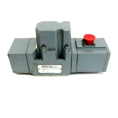
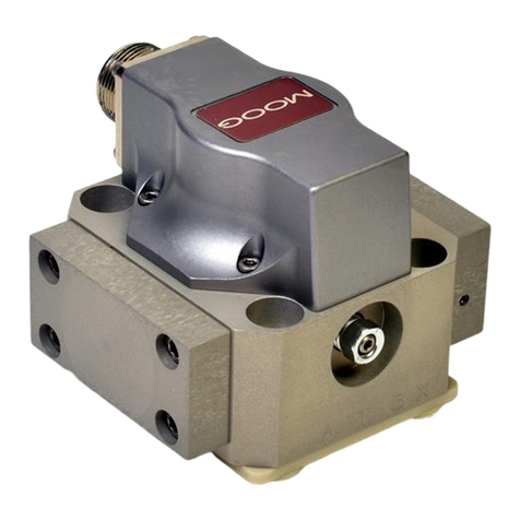
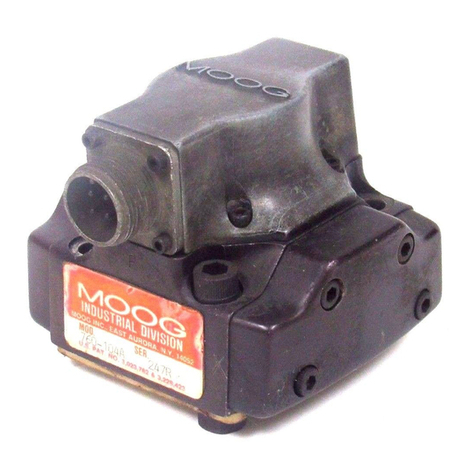
The Moog 62 Series Industrial Servovalve may be mounted in any position,
provided the servovalve pressure, control and return ports match respective
manifold ports. The mounting pattern and port location of the servovalve are
shown on Page 4. The servovalve should be mounted with 5/16-18 x 1 inch long
socket head capscrews and lockwashers. Torque the screws to 96 inch-pounds.
Wire the mating electrical connector for desired coil configuration and
polarity (see 62 Series Servovalve catalog, CDL6267). Thread connector to
valve.
5. MECHANICAL NULL ADJUSTMENT
It may be desirable to adjust the servovalve for flow null independent
of the other system parameters. The mechanical null adjustment permits
convenient control function set-ups. The “mechanical null adjustor” is a hex
socket set screw located behind the the pan head screw in the motor cap (see
Figure 2) which, when adjusted, provides control of the spool position to obtain
desired flow null.
NORMAL ADJUSTMENT SHOULD REQUIRE LESS THAN ± ONE TURN.
LIMIT NULL SCREW ADJUSTMENT TO LESS THAN ± TWO TURNS.
Adjustment Procedure
a. Ensure that zero electrical signal is applied to servovalve by disconnecting
electrical power to servovalve.
b. Using a blade screwdriver, remove pan head screw to permit
adjustment of hex socket set screw.
c. Using a 21/2inch long, 1/8 inch Allen wrench, adjust set screw to obtain
desired flow null.
NORMAL ADJUSTMENT SHOULD REQUIRE LESS THAN ± ONE TURN.
Note:
Clockwise orientation of set screw produces flow out control port B
d. After desired flow null has been obtained, install pan head screw.
e. Connect electrical power to servovalve.
Tools and Equipment
a. Blade screwdriver
b.
3/16 inch Allen wrench
c. Tweezers
d.
1/8 inch Allen wrench
e.
7/16 inch socket
6. GENERAL SERVICING RECOMMENDATIONS
a. Disconnect electrical lead to servovalve.
b. Relieve hydraulic system of residual pressure.
c. Remove servovalve.
Figure 2
Mechanical Null Adjustment
Table 1. Replacement Parts
Part Description Qty. Part Number
62 Series Filter Replacement Kit 1 B52555RK206K001
Inlet Orifice O-Ring (1) 2 -42082-012
Seal Plate (I) 2 CA86799-001
Base O-Ring 4 -42082-022
62 Series Orifice Filter Assembly (1) 2 A25446-001
(1) Included in 62 Series Filter Replacement Kit.
2 Moog•62SeriesOperationInstruction•RevE11/21
