manuals.online logo
Brands
  1. Home
  2. •
  3. Brands
  4. •
  5. IFM Electronic
  6. •
  7. Control Unit
  8. •
  9. IFM Electronic AC2028 User manual

IFM Electronic AC2028 User manual

Bestimmungsgemäße Verwendung
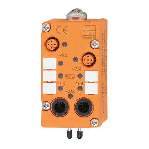
Die AS-i AirBox fungiert als Slave im AS-i-Netz (AS-i-Profil S 3.F). Sie
verbindet zwei Sensoren und zwei pneumatische Ausgänge mit dem
AS-i-Master.
• Sensorversorgung integriert.
• Sensoranschluß über Steckverbindung.
• Verbindung mit AS-i-Netz über Modul-Unterteil.
• Verbindung mit Pneumatik-System über Schlauchsteckverbinder
Legris 3000 / 8mm, außenkalibriert nach CETOP-Norm RP 54 P.
• Betrieb mit Druckluft von 2 bis 8 bar.
Montage
AS-i-Anschluß
Adressieren Sie die AS-i AirBox mit einem Adressiergerät, werksseitig
ist die Adresse „0“ eingestellt. Stecken Sie die AS-i AirBox auf das
Modul-Unterteil.
Druckluft
Befolgen Sie die Sicherheitsbestimmungen und Vorschriften für die
Einrichtung pneumatischer Anlagen. Schalten Sie die Anlage druckfrei.
Verbinden Sie die Anschlüsse für Druckluftzufuhr 1 (P), pneumatische
Ausgänge (O-3, O-4) und gegebenenfalls die Abluft 3 (R) mit dem
pneumatischen System. Schneiden Sie den Anschlußschlauch gerade
ab und schieben Sie ihn in die Steckverbindung, bis er hörbar einrastet.
Abziehen der Schläuche
Zum Lösen drücken Sie auf den schwarzen Ring und ziehen gleichzei-
tig den Schlauch heraus.
Mit den Handdruckknöpfen können Sie die pneumatischen Ausgänge
in Betrieb setzen. Lassen Sie Druckluft in die AS-i AirBox strömen.
Wenn Sie dann Handdruckknopf 1 drücken, wird der Ausgang O-3
angesteuert. Drücken Sie Handdruckknopf 2, wird der Ausgang O-4
angesteuert.
Die elektrische Ansteuerung hat Priorität gegenüber der
mechanischen.
Sensoren
Verbinden Sie die Sensoren mit den Eingängen I-1 und I-2.
Betrieb
Prüfen Sie, ob das Gerät sicher funktioniert. Anzeige durch LEDs:
• LED grün: Spannungsversorgung über das AS-i-Netz.
• LEDs gelb: Funktionsanzeige.
Für störungsfreien Betrieb muß ausreichend aufbereitete Luft verwen-
det werden (gefilterte Luft, geölt oder ungeölt). Wurde ein Bauteil mit
geölter Luft betrieben, so muß es weiterhin mit geölter Luft betrieben
werden, da das Öl die Initialschmierung entfernt hat.
Die Abluft wird je nach Geräteausführung mit einem Sinterfilter gerei-
nigt oder gefaßt abgeführt.
Montageanleitung
Installation instructions
Notice de montage
AS-i AirBox
AC2028
AC2029
I-1
I-2
O-3 O-4
Sachnr. 701212/02 03/98 Teile-Nr. 75.867 Technische Änderungen behalten wir uns ohne vorherige Ankündigung vor. Papier chlorfrei
1
3
4
5
2
Pin 1: “+”; Pin 2/4: input; Pin 3: “-”; Pin 5: nicht belegt;
Pin 2 und 4 miteinander verbunden;
Pin 1 - 5 female.
I-1
I-2
O-3 O-4
I-1
O-4
pwr.
O-3
I-2
Abluft 3 (R)
Sensoranschluß I-2
LEDs
Beschriftungsfelder
Steckanschluß
Druckluftzufuhr 1(P)
Handdruckknopf 2; für O-4
Sensoranschluß I-1
LEDs
Beschriftungsfelder
Pneumatische
Ausgänge
O-3 / O-4
Handdruckknopf 1; für O-3
Function and features
The AS-i Airbox is a slave in the AS-i system (AS-i profile S 3.F). It is the
connection between the two sensors, the two pneumatic outputs and
the AS-i master.
• Integrated sensor supply.
• Plug-in sensor connection.
• Connection to AS-i system via module lower part.
•Connection to pneumatic system via push fit tube connector Legris
3000 / 8mm, outside calibration according to CETOP standards RP 54 P.
•Operating pressure range of 2 to 8 bar.
Installation
AS-i connection
Address the AS-i Airbox with an addressing unit or via software, during
the manufacture the address “0" is preset into the AS-i module. Fit the
AS-i Airbox onto the module lower part.
Compressed air
Adhere to the safety regulations and provisions for the installation of
pneumatic systems. Switch off pressure.
Connect the compressed air supply 1 (P), the pneumatic outputs (O-3,
Fonctionnement et caractéristiques
L’Airbox AS-i est un esclave dans le réseau AS-i (profil AS-i S 3.F). Il éta-
blit la communication entre le maître et les deux capteurs et les deux
distributeurs pneumatiques.
• Alimentation des capteurs intégrée.
• Connexion embrochable M12 pour les capteurs.
• Raccord au réseau AS-i via un module de câblage (embase).
• Raccord pneumatique via le système Legris 3000 / 8mm, calibrage
extérieur selon la norme CETOP RP 54 P.
•Pression de service entre 2 et 8 bar.
Montage
Raccord AS-i
Adresser l’Airbox AS-i à l’aide d’une unité d’adressage (l’adresse “0"
étant présélectionnée à l’usine). Mettre l’Airbox AS-i sur son module
de câblage.
Air comprimé
Suivre les prescriptions de sécurité et les règlements pour l’installation
de systèmes pneumatiques. Mettre l’installation hors pression.
Raccorder l’alimentation en air comprimé 1 (P), les distributeurs pneu-
matiques (O-3, O-4) et, si nécessaire, l’échappement 3 (R). Il faut cou-
per droit les tuyaux et les pousser dans les raccords jusqu’au déclic.
Déconnexion des tuyaux
Pour enlever les tuyaux appuyer sur l’anneau noir et tirer le tuyau en
même temps.
Commande manuelle
Les commandes manuelles permettent d’activer les distributeurs pneu-
matiques. Si l’on appuie sur la commande manuelle 1, la sortie O-3 est
commutée. Si l’on appuie sur la commande 2, la sortie O-4 est com-
mutée.
La commande électrique est prioritaire sur la commande
manuelle.
Capteurs
Raccorder les capteurs aux entrées I-1 et I-2.
Fonctionnement
Vérifier le bon fonctionnement du module.
• LED verte: alimentation en tension via le réseau AS-i.
• LED jaunes: affichage des entrées / sorties.
Pour garantir le bon fonctionnement une quantité suffisante d’air doit
être utilisée. Si un composant est utilisé avec de l’air lubrifié, il faut
continuer à utiliser de l’air lubrifié.
Selon la version du module l’air s’évacue via un échappement avec
silencieux ou via un échappement direct.
O-4) and, if necessary, the exhaust 3 (R) to the pneumatic system. Cut
the connection tube straight and push it into the tube fitting until you
can feel the tube latch.
Removal of the tubes
To remove the tubes, push the black ring and pull out the tube at the
same time.
The manual overrides can operate the pneumatic outputs. Connect the
compressed air supply to the AS-i Airbox. If you then push the manual
override 1, the output O-3 is triggered. If you push the manual overri-
de 2, the output O-4 is triggered.
The electrical triggering has priority over the mechanical
triggering.
Sensors
Connect the sensors to the inputs I-1 and I-2.
Operation
Check the safe functioning of the unit. Display by LEDs:
• LED green: supply voltage via the AS-i system.
• LEDs yellow: function display.
For perfect functioning a sufficient quantity of treated air must be used
(filtered air, lubrified or not). If a component was used with lubrified
air, you must continue to use lubrified air because the oil in the air
supply removed the initial lubrication.
Depending on the unit version the exhaust air is filtered with a sinter-
ed exhaust or leaves via a common exhaust.
1
3
4
5
2
Wiring: pin 1: “+”; pin 2/4: input ;pin 3: “-”; pin 5: not used;
pins 2/4 linked;
pins 1-5 female.
I-1
I-2
O-3 O-4
I-1
O-4
pwr.
O-3
I-2
exhaust 3 (R)
sensor connection I-2
LEDs
tags for labelling
tube connection
compressed air
supply 1 (P)
manual override 2; for O-4
sensor connection I-1
LEDs
tags for labelling
pneumatic
outputs
O-3 / O-4
manual override 1; for O-3
1
3
4
5
2
Raccordement: broche 1: “+”; broche 2/4: entrée;
broche 3: “-”; broche 5: non utilisée;
broches 2/4 shuntées; broches 1-5 femelles.
I-1
I-2
O-3 O-4
I-1
O-4
pwr.
O-3
I-2
échappement 3 (R)
raccord capteur I-2
LED
étiquettes
raccord alimentation
en air comprimé 1(P)
commande manuelle 2; pour O-4
raccord capteur I-1
LED
étiquettes
sorties
pneumatiques
O-3 / O-4
commande manuelle 1; pour O-3

This manual suits for next models

1

Other IFM Electronic Control Unit manuals
IFM Electronic A5 interface AC535A User manual

IFM Electronic

IFM Electronic A5 interface AC535A User manual

IFM Electronic AS-i AC2505 User manual

IFM Electronic

IFM Electronic AS-i AC2505 User manual

IFM Electronic Ecomat100 CR1083 PDM360 NG User manual

IFM Electronic

IFM Electronic Ecomat100 CR1083 PDM360 NG User manual

IFM Electronic AS-i AC2086 User manual

IFM Electronic

IFM Electronic AS-i AC2086 User manual

IFM Electronic Efector 500 PP2001 User manual

IFM Electronic

IFM Electronic Efector 500 PP2001 User manual

IFM Electronic efector300 E40212 User manual

IFM Electronic

IFM Electronic efector300 E40212 User manual

IFM Electronic ecomot100 CR2012 Application guide

IFM Electronic

IFM Electronic ecomot100 CR2012 Application guide

IFM Electronic Ecomot 100 CR2511 Application guide

IFM Electronic

IFM Electronic Ecomot 100 CR2511 Application guide

IFM Electronic efector 600 TR2432 User manual

IFM Electronic

IFM Electronic efector 600 TR2432 User manual

IFM Electronic Ecomat 300 AC1154 User manual

IFM Electronic

IFM Electronic Ecomat 300 AC1154 User manual

IFM Electronic ecomat 100 CR2010 Application guide

IFM Electronic

IFM Electronic ecomat 100 CR2010 Application guide

IFM Electronic Efector110 User manual

IFM Electronic

IFM Electronic Efector110 User manual

IFM Electronic AS interface AC506S User manual

IFM Electronic

IFM Electronic AS interface AC506S User manual

IFM Electronic DN0301 User manual

IFM Electronic

IFM Electronic DN0301 User manual

IFM Electronic PDM360 NG-12 Owner's manual

IFM Electronic

IFM Electronic PDM360 NG-12 Owner's manual

IFM Electronic CR1083 User manual

IFM Electronic

IFM Electronic CR1083 User manual

IFM Electronic AC2380 User manual

IFM Electronic

IFM Electronic AC2380 User manual

IFM Electronic AC2261 User manual

IFM Electronic

IFM Electronic AC2261 User manual

IFM Electronic PDM360 NG User manual

IFM Electronic

IFM Electronic PDM360 NG User manual

IFM Electronic efector 300 SR5906 User manual

IFM Electronic

IFM Electronic efector 300 SR5906 User manual

IFM Electronic Efector 500 User manual

IFM Electronic

IFM Electronic Efector 500 User manual

IFM Electronic Ecomat 300 AC2618 User manual

IFM Electronic

IFM Electronic Ecomat 300 AC2618 User manual

IFM Electronic Ecomat 300 AL1030 Application guide

IFM Electronic

IFM Electronic Ecomat 300 AL1030 Application guide

IFM Electronic efector 600 TR7430 User manual
IFM Electronic

IFM Electronic efector 600 TR7430 User manual

Popular Control Unit manuals by other brands

Lennox V8MSBB01 installation instructions

Lennox

Lennox V8MSBB01 installation instructions

Zeta DYCU-3 Operation manual

Zeta

Zeta DYCU-3 Operation manual

AMX CAT-5 RGBHV RX quick start guide

AMX

AMX CAT-5 RGBHV RX quick start guide

Vivax Metrotech vLoc3-RTK-Pro quick start guide

Vivax Metrotech

Vivax Metrotech vLoc3-RTK-Pro quick start guide

Timotion TDH9P user manual

Timotion

Timotion TDH9P user manual

Siemens SIRIUS ACT 3SU1400-1GE10-1AA0 Original operating instructions

Siemens

Siemens SIRIUS ACT 3SU1400-1GE10-1AA0 Original operating instructions

Pentair PERFORMA CV Series Service manual

Pentair

Pentair PERFORMA CV Series Service manual

FA goods FA-TB16XYPN user manual

FA goods

FA goods FA-TB16XYPN user manual

Ravel RE-717MC Installation and maintenance instructions

Ravel

Ravel RE-717MC Installation and maintenance instructions

Kallista P23083-CR installation instructions

Kallista

Kallista P23083-CR installation instructions

Panasonic GPKS162CUD - CONTROL UNIT operating instructions

Panasonic

Panasonic GPKS162CUD - CONTROL UNIT operating instructions

IMTH.de SST1 Installation guide and user's manual

IMTH.de

IMTH.de SST1 Installation guide and user's manual

Tool-Temp TT-180 manual

Tool-Temp

Tool-Temp TT-180 manual

BVA Hydraulics PW2 instruction manual

BVA Hydraulics

BVA Hydraulics PW2 instruction manual

Inovonics EE1941 Installation and operation manual

Inovonics

Inovonics EE1941 Installation and operation manual

ARMATURA AMT-FAPVS-21 user manual

ARMATURA

ARMATURA AMT-FAPVS-21 user manual

VPro MA Series instruction manual

VPro

VPro MA Series instruction manual

Red Valve Tideflex Series Installation, operation and maintenance manual

Red Valve

Red Valve Tideflex Series Installation, operation and maintenance manual

manuals.online logo
manuals.online logoBrands
  • About & Mission
  • Contact us
  • Privacy Policy
  • Terms and Conditions

Copyright 2025 Manuals.Online. All Rights Reserved.