Moon Valley M-200 User manual

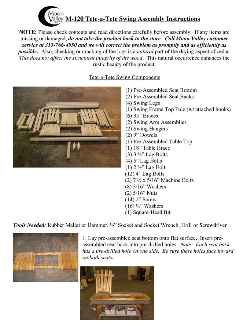
M-200 Double Glider Assembly Instructions
NOTE: Please check contents and read directions carefully before assembly. If any items are missing or damaged, do not take the
product back to the store. Call Moon Valley customer service at 313-766-4950 and we will correct the problem as promptly and
as efficiently as possible. Also, checking or cracking of the logs is a natural part of the drying aspect of cedar. This does not affect
the structural integrity of the wood. This natural occurrence enhances the rustic beauty of the product.
Double Glider Components
(2) Pre-Assembled Seat Backs (A)
(2) Pre-Assembled Seats Bottoms (B)
(4) Arm Assemblies (R)
(4) Swing Hangers (D)
(2) Doweled Top Poles (M)
(2) Top Poles w/ Metal Hangers (N)
(4) Angle Braces (P)
(4) 35” Braces (Q)
(4) Swing Frame Legs (I)
(1) Glider Platform (J)- Assembly Instructions Attached
(2) Galvanized Metal Platform Support Pipes (K)
7 ¾” x 3/8” Machine Bolts (C) See attached sheet
5” Lag Bolts(F) See attached sheet
4” Lag Bolts (G) See attached sheet
3/8” Washers (U) See attached sheet
3/8” Nuts (X) See attached sheet
2” Square-Head Screws (O) See attached sheet
3 ½” Lag Bolts (H) See attached sheet
4” x 1/4” Machine Bolts (E) See attached sheet
1/4” Washers (W) See attached sheet
1/4” Nuts (Z) See attached sheet
Plastic Spacers (L) See attached sheet
Square-Head Screw Bit See attached sheet
Tools Required: Rubber Mallet (or Hammer), Drill (or screwdriver) w/ Square-Head Bit, Ratchet with
9/16”, 7/16”, 11mm and ½” Sockets, Tape Measure.
A
B
R
D
D
R
R
R
A
B
Q
N
I
J
P
M
K

Section 1: Frame Assembly
Step 1: Insert doweled ends 51” top poles (M) into the pre-drilled holes on the
72” top poles (N) (w/ metal hangers). Be sure that metal hangers are facing up
like in the photo. Attach these pieces together with one 2” screw (O) into each
insertion point (as shown). Repeat process to make
square frame (shown below).
Step 2: Through the pre-drilled holes, attach angled end of each leg (I) to the
assembled frame using 7 3/4” machine bolts (C) (as shown). Be sure to insert the
bolt from the inside, using a 3/8” washer (U) on each side. Secure with 3/8” nuts
(X). Note: Only tighten nuts (X) enough to allow frame to stand on its own. Do
not fully tighten at this point. Repeat process on all remaining legs (I). Please note
that the machine bolt will extend past the frame. This allows the option of a
canopy to be put on at a later time.
Step 3: Lift frame allowing it to stand freely (this may require a second person).
Be sure nuts (X) are tightened enough to prevent frame from collapsing.
Step 4: From machine bolt (C), measure down 29” to the inside of the leg (I)
and mark (as shown). Repeat process on all legs (I).
Step 5: Using this mark, attach 45 ½” angle braces (P) to inside of legs using 5” lag
bolts (F) through pre-drilled holes (as shown). Note: angled ends of each brace
will differ in degree, allowing for correct fit to legs and frame. Be sure to reverse
each brace to ensure correct angle before attaching.
Step 6: Attach opposite end of angle brace (P) using 5” lag bolts (F) (as shown).
Repeat process for remaining braces.
Metal Hanger
facing up
M
M
N
N
M
N
I
N
I
I
P
P

Section 2: Swing Seat Assembly
Step 7: Attach both swing arm assemblies (R) to swing seats (B). Make sure the side of the swing arm
assembly is with the dowel is facing towards the front of the seat. Align
the two doweled ends of swing seat (B) with the two holes in the swing
arm assembly (R). Tap arms into place using rubber mallet or hammer. If
using a hammer, be sure to pad impact area to avoid damage to the
product.
Step 8: Attach pre-assembled seat back (A) to remaining holes at the rear
of arm assemblies (R). Tap arms into place with rubber mallet or hammer.
Step 9: Line up part (A) and part (R) at the angle most comfortable for the
user. Use the 3 1/2” lag bolt and washer (H) to secure the arms to the seat back
(A) (as shown).
Photo shows seat back (A)/arm unit (R)
Step 10: Install 2” screw (O) where all doweled ends are inserted, securing
seat (B) and seat back (A) to arm assemblies (R).
Photo shows front of seat (B)/arm unit (R)
Step 11: Attach swing hangers (D) to arm assemblies (R) using 5” lag bolts and
washer (F). Align pre-drilled holes on swing hanger (D) to swing arm assembly
(R) at 11 ½” from front of log (R) making sure that metal hanger iron is facing
up. Insert one lag bolt and washer (F) to upper arm only at this point.
Step 12: Slide two plastic spacers (L) onto each metal platform support pipe (K). Next,
insert support pipe (K) into pre-drilled holes at bottom of swing hangers (D) (as shown).
Be sure that pre-drilled hole in pipe (K) lines up with pre-drilled hole at bottom of swing
hanger (D).
Step 13: Insert 4” x 1/4” machine bolt (E) through pre-drilled holes in swing hanger (D)
and pipe (K). Use 1/4”washer on each side and secure with 1/4” nut. Repeat process on
other swing seat.
Step 14: Use 5” lag bolts (F) to secure swing hangers (D) to bottom section of swing
arms at 12 ¾” from front of log (R).
B
R
Front
A
R
B
R
Front of seat
D
R
L
L
K
K
D
D
R

Section 3: Swing on Frame Assembly
Step 15: Hang swing seats inside of frame, each seat facing inward. Next, measure
3” from swing hanger (D) to angle brace on frame (P). Adjust frame legs (I) to make
sure this distance equals 3”, and fully tighten 6 ½ x 3/8” frame bolts (securing legs to
frame).
Step 16: From top of leg (I), measure 22” down to outside of leg and mark. At this
mark, use one 4” lag bolt (G) through pre-drilled hole on 35” brace (Q), securing it to
swing leg (I) (as shown). Next, use another 4” lag bolt (G) to secure other end of
brace to the frame, at any angle desired (as shown below).
Step 17: Set glider platform (J) onto support pipes (K). Be sure that plastic spacers
(L) are placed between platform and swing hangers.
Note: if you have extra hardware left over after assembly, these may be a problem and your swing may not be safe
to use. Double-check directions to ensure that all hardware is installed correctly and tightened. If the problem
persists, please call Moon Valley customer service at 313-766-4950.
With Double Glider Canopy (sold separately) Without Double Glider Canopy
Thank you for your Moon Valley purchase and we hope that you enjoy your Double Glider. To view other
Moon Valley products, or to purchase a Double Glider Canopy, please contact your local dealer or visit us at
www.moonvalleyrustics.com.
Moon Valley Rustics
4658 South Custer Rd, Monroe, Mi 48162
Phone Number: (313) 766-4950 www.moonvalleyrustics.com
September 2017. Do not let children play with plastic bags.
I
P
3” From “D” to “P”
Q
I
J
K

Double Glider Platform Assembly Instructions
Material List:
(2) 52” 2x4
(4) 44” 2x10
(16) 2½ inch screws
Place the two 2x4 pieces on a flat level surface 44 inches apart (outside of board to outside
of board) with the notches facing down.
Place one 2x10 boards 7 inches from the corner across the 2x4’s horizontally and flush
with the outside edge. Attach using four of the 2½ screws per board. Place the last three
2x10 boards approximately ¼ inch apart from each other horizontally in a row and fasten
with 2 ½ inch screws.
Moon Valley Rustics
4658 South Custer Rd, Monroe, Mi 48162
Phone Number: (313) 766-4950 www.moonvalleyrustics.com
September 2017. Do not let children play with plastic bag.
This manual suits for next models
3
Table of contents
Other Moon Valley Outdoor Furnishing manuals
Popular Outdoor Furnishing manuals by other brands
Net World Sports
Net World Sports Single Boot wiper Assembly instructions

HAPPATIO
HAPPATIO HPO-ZPTY-H owner's manual

neighbor
neighbor Teak Low Chair and Ottoman Assembly guide

Sunjoy
Sunjoy D-SC002PAL ASSEMBLY INTRUCTION

Sunjoy
Sunjoy L-PG080PST-K Assembly instruction

FUJIEI
FUJIEI Nychair X Assembly and instruction manual