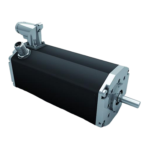
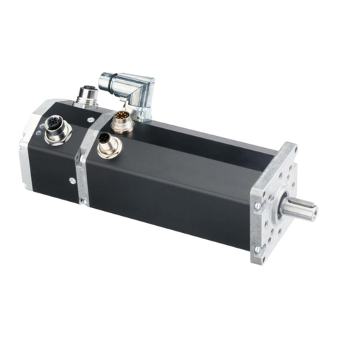
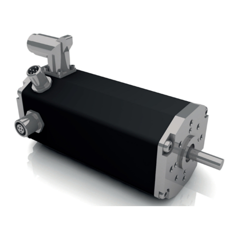
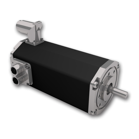
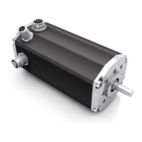
Ametek dunkermotoren BG 75 SI Series User manual

Edition / Ausgabe (05/2017)
Instruction Manual / Betriebsanleitung
BLDC-motor with integrated speed controller
EC-Motor mit integriertem Drehzahlregler
BG 75 SI

2Instruction Manual/Betriebsanleitung BG75SI, Version: 1.1 en_de
© 2011 Dunkermotoren GmbH; D-79848 Bonndorf; Germany
Page
1 Contents 2
2 About this document 4
3 General description 5
3.1 Motor series BG 75 SI 5
3.2 Explanations of terms used 6
3.3 Proper use 6
3.4 Standards and guidelines 7
4 Safety instructions 8
5 Technical data, accessories 9
5.1 Electrical data 9
5.2 Mechanical data 10
5.3 Dimensions 10
5.4 Motor BG 75x25 SI 11
5.5 Motor BG 75x50 SI 11
5.6 Motor BG 75x75 SI 11
5.7 Accessories 12
6 Protective functions 13
6.1 Ballast circuit 13
6.2 Over-temperature protection 13
6.3 Current limitation 13
7 Installation / terminal assignment 14
7.1 Mechanical assembly 14
7.2 Electromechanical compatibility 15
7.3 Ground wire 15
7.4 Connection alternatives 16
7.5 Motor power supply 16
7.6 Signal interface supply 17
7.7 Schematic circuit of the digital outputs 19
7.8 Schematic circuit of the digital inputs 20
7.9 Maximum cable length and
power supply 20
8 Connection schematic 21
8.1 Schematic circuit for power supply
controller/ motor BG75 SI 22
8.2 Connection motor power
supply 23
8.3 Connection signal interface supply 23
9 Operation hints 24
9.1 Operation 25
9.2 Function of the digital inputs
IN0 and IN1 25
Seite
1 Inhalt 2
2 Über dieses Dokument 4
3 Allgemeine Beschreibung 5
3.1 Motorbaureihe BG 75 SI 5
3.2 Begriserklärungen 6
3.3 Bestimmungsgemäße Verwendung 6
3.4 Normen und Richtlinien 7
4 Sicherheitshinweise 8
5 Technische Daten, Zubehör 9
5.1 Elektrische Daten 9
5.2 Mechanische Daten 10
5.3 Motormaßzeichnung 10
5.4 Motor BG 75x25 SI 11
5.5 Motor BG 75x50 SI 11
5.6 Motor BG 75x75 SI 11
5.7 Optionale Anbauten 12
6 Schutzfunktionen 13
6.1 Ballastschaltung 13
6.2 Übertemperaturschutz 13
6.3 Strombegrenzung 13
7 Installation und Anschlussbelegung 14
7.1 Mechanische Montage 14
7.2 Elektromagnetische Verträglichkeit 15
7.3 Schutzleiter Anschluss 15
7.4 Anschlussmöglichkeiten 16
7.5 Leistungsversorgung Motor 16
7.6 Schnittstellenversorgung 17
7.7 Prinzipschaltung der Digitaleingänge 19
7.8 Prinzipschaltung der Digitalausgänge 20
7.9 Maximale Kabellänge und
Spannungsversorgung 20
8 Anschlussschema 21
8.1 Prinzipschaltbild Spannungs
versorgung Regler/ Motor BG75 SI 22
8.2 Anschluss Leistungsversorgung
Motor 23
8.3 Anschluss Schnittstellenversorgung 23
9 Betriebshinweise 24
9.1 Inbetriebnahme 25
9.2 Funktion der Digitaleingänge
IN0 und IN1 25

3
Instruction Manual/Betriebsanleitung BG75SI, Version: 1.1 en_de
© 2011 Dunkermotoren GmbH; D-79848 Bonndorf; Germany
9.3 Function of the digital inputs
IN2 and IN3 25
9.4 Teaching of xed speeds 26
9.5 Teaching of ramps 27
9.6 Function of the pulse output OUT1 29
9.7 Protection function and fault output
OUT2 30
9.8 Function of the analogue input
AI+/AI- 31
9.9 Motors with additional brake 32
10 Maintenance & Service 33
10.1 Maintenance, taking out of service
and disposal 33
10.2 Service & Support 33
10.3 Scope of delivery and accessories 34
10.4 Download PDF-Data 34
11 Appendix 35
A) CE-declaration of the manufacturer 35
9.3 Funktion der Digitaleingänge
IN2 und IN3 25
9.4 Teachen von festen Geschwindigkeiten 26
9.5 Teachen von Rampen 27
9.6 Funktion des Pulsausgangs OUT1 29
9.7 Schutzfunktionen und Meldeausgang
OUT2 30
9.8 Funktion des Analogeinganges
AI+/AI- 31
9.9 Motoren mit zusätzlicher Bremse 32
10 Wartung & Service 33
10.1 Wartung, Ausserbetriebsetzung
und Entsorgung 33
10.2 Service & Support 33
10.3 Lieferumfang und Zubehör 34
10.4 Download PDF-Daten 34
11 Anhang 35
A) CE-Herstellererklärung 35

4Instruction Manual/Betriebsanleitung BG75SI, Version: 1.1 en_de
© 2011 Dunkermotoren GmbH; D-79848 Bonndorf; Germany
2 About this document
These operating instructions introduce you to the SI
drives and provide you with information on all the
stages required for the installation of the drives and
the performance of functional tests.
2 Über dieses Dokument
Die vorliegende Betriebsanleitung stellt Ihnen die SI-
Antriebe vor und informiert Sie über alle Schritte zur
Installation der Antriebe und zur Durchführung von
Funktionstests.
Before commissioning, it is
essential that the safety instructions
in the relevant section are read and
understood, and then observed!
Non-observance can result in danger
to persons or damage to the machine.
► Disconnect the electrical power
supply!
Vor der Inbetriebnahme sind unbe-
dingt die Sicherheitshinweise zu lesen
und zu beachten! Eine Nichtbeach-
tung kann zu Gefahren bei Personen
oder Beschädigungen an der
Maschine führen.
► Gerät spannungsfrei
schalten !
WARNUNG
WARNING
Lesen und befolgen Sie in diesem
Dokument die Warnhinweise
sorgfältig. Die Warnhinweise sollen
Sie vor Gefahr schützen oder helfen
Ihnen, eine Beschädigung des
Gerätes zu vermeiden.
HINWEIS
Read and observe the warnings in this
dokument. Warnings are there
to protect you from danger, and to
help you to avoid damage to
the device.
NOTICE
Hinweise erläutern Ihnen Vorteile
bestimmter Einstellungen und helfen
Ihnen, den optimalen Nutzen aus dem
Gerät zu ziehen.
HINWEIS
Instructions explain the advantages of
certain settings and help you use the
device to the best possible eect.
NOTICE

5
Instruction Manual/Betriebsanleitung BG75SI, Version: 1.1 en_de
© 2011 Dunkermotoren GmbH; D-79848 Bonndorf; Germany
Hall sensors integrated/
Integrierte Hallsensoren Output shaft, optional attached gearbox/
Antriebswelle, optional angebautes Getriebe
BLDC-motor/ EC-Motor
2 Plugs for power and logic supply /
2 Motorstecker für Leistungsversorgung und Logik
Encoder integrated /
integrierter Inkrementalgeber
optional attached brakes/
optional angebaute Bremse
Power and control elecronics integrated/
Leistungs- und Steuerelektronik (integriert)
3 General description
3.1 Motor series BG 75 SI
The motor type BG 75 SI represents EC-motors
(brushless DC motor) with an integrated speed control
electronic for 4-quadrant operation.
The desired speed is set via an analogue signal input
0 ... +10 V. The four operating modes “clockwise rota-
tion”, “counter clockwise rotation”, “O” (rapid break-
point with freewheel) and “Stop” (rapid breakpoint with
holding torque) are controlled via the two digital inputs
IN0 and IN1. Optional, two further digital inputs for
additional functions are available. Therewith, among
other things, 2 xed motor speeds (e.g. for rapid
movement and creep speed), acceleration ramp and
braking ramp can be memorized (Teach). Two digital
output signals are available additionally: one giving
12 pulses per turn (e.g. for position and speed con-
trol), the other showing “fault”.
By means of of the integrated incremental encoder
with a resolution 4096 (4x 1024) increments per revo-
lution, a very high positioning accuracy with very good
regulating characteristics can be achieved.
In case of larger needs, customer specic solu-tions
with special rmware are available on request.
The motor has except of the ball bearings no expen-
dable parts and is hence excellently suited for conti-
nuous operation. The motors BG 75 SI can be com-
bined with planetary or worm gears with a multitude
of ne tuned gear ratios.
3 Allgemeine Beschreibung
3.1 Motorbaureihe BG 75 SI
Bei der Motorbaureihe BG 75 SI handelt es sich um
EC-Motoren (bürstenlose DC-Motoren) mit einer inte-
grierten Drehzahlregelelektronik für den
4-Quadrantenbetrieb.
Die Drehzahlsollwertvorgabe erfolgt standardmäßig
über einen Analogspannungseingang 0 ... +10 V.
Über zwei digitale Eingänge (IN0, IN1) lassen sich die
vier Betriebszustände „Rechtslauf“, „Linkslauf“, „Aus“
(Schnellstopp mit Freilauf) und „Stopp“ (Schnellstopp
mit Haltemoment) ansteuern. Wahlweise stehen zwei
weitere digitale Eingänge für erweiterte Funktionalität
zur Verfügung. Damit lassen sich unter anderem 2
feste Motordrehzahlen (z.B. für Eil- und Schleichgang)
und Beschleunigungs- und Bremsrampen (z. B. für
sanftes Beschleunigen und Abbremsen) abspeichern
(teachen). Außerdem werden zwei digitale Ausgänge
herausgeführt, womit ein Pulsausgang mit 12 Impul-
sen pro Umdrehung (z. B. für Positions- und Ge-
schwindigkeitsüberwachung) und eine Fehlermeldung
zur Verfügung stehen.
Durch den integrierten Inkrementalgeber mit einer Auf-
lösung von 4096 (4x 1024) Inkrementen pro Umdre-
hung werden eine hohe Positioniergenauigkeit und
sehr gute Regeleigenschaften erreicht.
Kundenspezische Ausführungen mit spezieller
Firmware sind bei größeren Bedarfsfällen auf Anfrage
möglich.
Der Motor hat außer den Kugellagern keine Ver-
schleißteile und eignet sich deshalb hervorragend
auch für Dauerbetrieb. Die Motoren BG 75 SI können
auch mit Planeten- oder Schneckengetrieben kombi-
niert werden, die in einer Vielzahl fein abgestimmter
Untersetzungen verfügbar sind.

6Instruction Manual/Betriebsanleitung BG75SI, Version: 1.1 en_de
© 2011 Dunkermotoren GmbH; D-79848 Bonndorf; Germany
3.2 Explanations of terms used
Bridge rectier
Component for the transfor-
mation from AC voltage to DC
voltage
Smoothing capaci-
tor
Component to smooth the
uctuation voltage
Hall sensors Sensors for determining the
position of a rotor
Index impuls Reference mark of the inte-
grated encoder panel
Ramps Settings to accelerate and brake
the drive
CAN-Monitor Adjustment- and storring possi-
bility for speed and ramps
3.3 Proper use
- The BG 75 SI motor is a supplied part and may
be installed into (industrial) machinery and
equipment in the described conguration.
- The drive must be securely xed, and may only be
installed using cables and components specied by
Dunkermotoren.
- The drive may only be put into operation once the
entire system has been installed in accordance with
EMC. Please follow the instructions in chapter 7.2.
3.2 Begriserklärungen
Brückengleichrich-
ter
Bauteil zur Umwandlung von
Wechselspannung in Gleich-
spannung
Glättungskonden-
sator
Bauteil zur Glättung von
Spannungsschankungen
Hallsensoren Sensor zur Positionsbestim-
mung des Rotors
Indeximpuls Referenzmarke der inte-
grierten Geberscheibe
Rampen Einstellungen zum Beschleuni-
gen und Bremsen des Antriebs
Teachen / Toggeln
Einstellung undAbspeichermög-
lichkeit für Geschwindigkeiten
und Rampen
3.3 Bestimmungsgemäße Verwendung
- Der Motor BG 75 SI ist ein Zulieferteil und
darf in der beschriebenen Konguration in
Maschinen und Anlagen eingesetzt werden
(industrieller Bereich).
- Der Antrieb muss fest montiert werden und darf nur
mit den von Dunkermotoren spezizierten Kabeln
und Zubehörteilen eingesetzt werden.
- Der Antrieb darf erst nach EMV-gerechter Montage
des Gesamtsystems in Betrieb genommen werden.
Beachten Sie hierzu die Anweisungen in Kap. 7.2.

7
Instruction Manual/Betriebsanleitung BG75SI, Version: 1.1 en_de
© 2011 Dunkermotoren GmbH; D-79848 Bonndorf; Germany
3.4 Standards and guidelines
EU guidelines: the EU guidelines formulate the mi-
nimum requirements made on a product and must be
observed by all manufacturers and dealers marketing
the product in the member states of the European
Union.
Machine guideline: the drive is a machine in the sense
of the EU guideline for machinery. It has moveable
parts in accordance with its intended purpose: ho-
wever, it may only be installed as a component of a
machine or a system. The advice described in these
instructions regarding installation and operation must
be adhered to.
EMC guideline: the EU guidelines for EMC apply to
devices which can cause electromagnetic interrup-
tions or whose operation can be impaired by these
interruptions. Compliance of the drive with the EMC
guideline can only be tested once it has been instal-
led. The information pertaining to EMC described in
these instructions must be adhered to.
Conformity: by means of the conformity declaration
of the product (see appendix), Dunkermotoren con-
rms that the drive complies with the safety standards
listed therein and with EMC standards. The product
may be sold and used within the European Union.
3.4 Normen und Richtlinien
EG-Richtlinien: Die EG-Richtlinien formulieren die
Mindestanforderungen an ein Produkt und müssen
von allen Herstellern und Händlern beachtet werden,
die das Produkt in den Mitgliedstaaten der Europä-
ischen Union auf den Markt bringen.
Maschinenrichtlinie: Der Antrieb ist eine Maschine
im Sinne der EG-Richtlinie für Maschinen. Er hat
zweckgerichtet bewegliche Teile, darf aber nur als
Bestandteil einer Maschine oder Anlage eingesetzt
werden. Die in dieser Betriebsanleitung beschrie-
benen Hinweise zur Installation und Inbetriebnahme
müssen beachtet werden.
EMV-Richtlinie: Die EG-Richtlinien für EMV gelten
für Geräte, die elektromagnetische Störungen ver-
ursachen können oder deren Betrieb durch diese
Störungen beeinträchtigt werden kann. Die Überein-
stimmung des Antriebs mit der EMV-Richtlinie kann
erst nach dem Einbau überprüft werden. Die in dieser
Betriebs-anleitung beschriebenen Angaben zur EMV
müssen beachtet werden.
Konformität: Mit der Konformitätserklärung (siehe
Anhang) des Produkts bescheinigt Dunkermotoren,
dass der Antrieb den dort aufgeführten Normen zur
Sicherheit und EMV entspricht. Das Produkt darf in
der Europäischen Union vertrieben und eingesetzt
werden.

8Instruction Manual/Betriebsanleitung BG75SI, Version: 1.1 en_de
© 2011 Dunkermotoren GmbH; D-79848 Bonndorf; Germany
4 Safety instructions 4 Sicherheitshinweise
Before commissioning, it is
essential that the safety instructions
in the relevant section are read and
understood, and then observed!
Non-observance can result in danger
to persons or damage to the machine.
► Disconnect the electrical power
supply!
Vor der Inbetriebnahme sind unbe-
dingt die Sicherheitshinweise zu lesen
und zu beachten! Eine Nichtbeach-
tung kann zu Gefahren bei Personen
oder Beschädigungen an der
Maschine führen.
► Gerät spannungsfrei
schalten !
WARNUNG
WARNING
Die Antriebe dürfen nur von
qualiziertem Personal nach den
entsprechenden Normen eingebaut
und eingerichtet werden.
Als qualiziert gilt eine Person dann,
► wenn ihre Erfahrung mögliche Gefahren
vermeiden kann.
► wenn ihr die Unfallverhütungsvor-
schriften bekannt sind.
► wenn sie gemäß den Normen Stromkreise
und Geräte in Betrieb setzen und
installieren darf.
HINWEIS
The drive must only be installed
and adjusted by qualied persons
in accordance with the relevant
standards.
Qualied persons are those who:
► on the basis of their experience, can
recognise and avoid potential dangers.
► are familiar with the accident-prevention
regulations for the equipment deployed.
► are able to connect circuits and install
equipment in accordance with the
standards and regulations.
NOTICE
Der störungsfreie Betrieb setzt
entsprechende Lagerung und
Transport nach den entsprechenden
Vorgaben voraus.
Lagern Sie bitte den Antrieb geschützt vor:
► Staub, Schmutz und Feuchtigkeit!
Achten Sie auch auf die Lagerbedingungen:
► z.B. Lagerungstemperatur!
(Siehe technische Daten)
Transportieren Sie die Antriebe unter
Lagerbedingungen:
► stoßgeschützt
HINWEIS
To ensure trouble-free operation,
appropriate methods of transport and
conditions of storage must be
deployed.
Please store the drive so that it is protected from:
► dust, dirt and moisture
Take care also at the storage conditions:
► e.g. storage temperature!
(See technical data)
Transport the drive under storage
conditions
► protection against shock
NOTICE

9
Instruction Manual/Betriebsanleitung BG75SI, Version: 1.1 en_de
© 2011 Dunkermotoren GmbH; D-79848 Bonndorf; Germany
5 Technical data, accessories
5.1 Electrical data
Speed range
adjustable 0 ... 4092 U/min
Minimum motor
voltage 7 V DC
Maximum motor voltage50 V DC
Maximum ripple on
supply voltage Max. 5 %
Recommended logic supply 24 V */- 20%
Undervoltage shutdown
Logic < 16,5 V
Demolition boundary > 58 V
Required
external fuse 25 AT external
Over-temperature
protection
> 110°C at the
power output stage
Max. peak current (2 sec.)
up to 30° C (motor) 50 A
Max. peak current up to
100° C (motor) 30 A
Current consumption
of 24 V-logic supply
70 mA + power of
digital outputs
5 Technische Daten, Zubehör
5.1 Elektrische Daten
Regelbarer Drehzahl-
bereich 0 ... 4092 U/min
Minimal zulässige
Motorspannung 7 V DC
Maximal zulässige
Motorspannung 50 V DC
Zulässige Restwelligkeit
der Versorgungsspannung Max. 5 %
Empfohlene Logikspan-
nung 24 V */- 20%
Unterspannungsabschal-
tung Logik < 16,5 V
Zerstörungsgrenze > 58 V
Absicherung 25 AT extern
erforderlich
Übertemperaturabschal-
tung
> 110°C an der
Leistungsendstufe
Max. Spitzenstrom (2 sek.)
bis 30° C (Wicklung) 50 A
Max. Spitzenstrom
bis 100° C (Wicklung) 30 A
Stromaufnahme
der 24 V-Logikversorgung
70 mA + Strom digi-
taler Ausgänge

10 Instruction Manual/Betriebsanleitung BG75SI, Version: 1.1 en_de
© 2011 Dunkermotoren GmbH; D-79848 Bonndorf; Germany
5.2 Mechanical data
Temperature range
motor
-20 °C ... +100 °C
housing temperature
Recommended envi-
ronmental temperature
range *)
0 °C ... 50 °C
Relative humidity
(not condensing) Max. 90%
Protection class **) IP50 (in special versions
up to IP65)
Connector plug
12-pole ***)
Round connector accor-
ding DIN 45326, compa-
ny Amphenol, C091
*) The motor is specied for an ambient temperature
of 20°C. The performance data refer to this ambient
temperature.
**) The protective system only refers to the motor /
gearbox casing. The shaft is to be sealed by the client.
The drive may only be used in an environment com-
plying with IP54 if the shaft outlet has been installed
such that it is protected from dust and water.
***) Please see the pin diagram for further information.
5.3 Dimensions
5.2 Mechanische Daten
Temperaturbereich
Motor
-20°C…+100°C
Gehäusetemperatur
Empfohlener Umge-
bungstemperaturbereich *) 0°C…50°C
Relative
Luftfeuchtigkeit Max. 90%
Schutzart **) IP 50 (in Sonderaus-
führungen bis IP 65)
Anschlussstecker
12-polig ***)
Rundstecker nach
DIN 45326, Firma
Amphenol, C091
*) Der Motor ist für eine Umgebungstemperatur von
20°C speziziert. Die Leistungsangaben beziehen sich
auf diese Umgebungstemperatur.
**) Die angegebene Schutzart bezieht sich nur auf das
Motor- bzw. Getriebegehäuse. Die Abdichtung der Welle
ist vom Kunden vorzunehmen. Nur wenn der Wellenau-
stritt staub- und wassergeschützt montiert wird, kann der
Antrieb in einer Umgebung entsprechend IP54 einge-
setzt werden.
***) Weitere Informationen nden Sie im Abschnitt An-
schlussbelegung.
5.3 Motormaßzeichnung

11
Instruction Manual/Betriebsanleitung BG75SI, Version: 1.1 en_de
© 2011 Dunkermotoren GmbH; D-79848 Bonndorf; Germany
5.4 Motor BG 75x25 SI
Nominal voltage 24V 40V
Nominal power 250 W 284 W
Rated speed 3900 rpm 3820 rpm
Nominal torque *) 61 Ncm 71 Ncm
Nominal current 12,2 A 8,3 A
Connector lenght 107 mm
Weight approx. 1660 g
5.5 Motor BG 75x50 SI
Nominal voltage 24V 40V
Nominal power 320 W 400 W
Rated seed 4050 rpm 3900 rpm
Nominal torque *) 76 Ncm 98 Ncm
Nominal current 16,0 A 11,2 A
Connector length 132 mm
Weight approx. 2200 g
5.6 Motor BG 75x75 SI
Nominal voltage 40 V
Nominal power 450 W
Rated speed 3700 rpm
Nominal torque *) 116 Ncm
Nominal current 12,7 A
Connector length 157 mm
Weight approx. 2800 g
*) The nominal torque depends on the motor‘s heat
dissipation. The tables thus list the values taken in
accordance with VDE (the German Electrical Engi-
neers’ Association) / EN (European Standard) and
taken during the installation of a thermally-conductive
steel plate with the dimensions 105x105x10mm (data
inbrackets).
5.4 Motor BG 75x25 SI
Nennspannung 24V 40V
Nennleistung 250 W 284 W
Nenndrehzahl 3900 rpm 3820 rpm
Nenndrehmoment *) 61 Ncm 71 Ncm
Nennstrom 12,2 A 8,3 A
Steckerlänge 107 mm
Gewicht ca. 1660 g
5.5 Motor BG 75x50 SI
Nennspannung 24V 40V
Nennleistung 320 W 400 W
Nenndrehzahl 4050 rpm 3900 rpm
Nenndrehmoment *) 76 Ncm 98 Ncm
Nennstrom 16,0 A 11,2 A
Steckerlänge 132 mm
Gewicht ca. 2200 g
5.6 Motor BG 75x75 SI
Nennspannung 40 V
Nennleistung 450 W
Nenndrehzahl 3700 rpm
Nenndrehmoment *) 116 Ncm
Nennstrom 12,7 A
Steckerlänge 157 mm
Gewicht ca. 2800 g
*) Das Nenndrehmoment ist abhängig von der Wär-
meabführung des Motors. In den Tabellen aufgeführt
sind deshalb die Werte gemessen nach VDE/EN so-
wie gemessen bei Montage einer thermisch leitenden
Stahlplatte der Größe 105 x 105 x 10 mm (Angabe in
Klammern).

12 Instruction Manual/Betriebsanleitung BG75SI, Version: 1.1 en_de
© 2011 Dunkermotoren GmbH; D-79848 Bonndorf; Germany
5.7 Accessories
Worm gear (WG):
The worm gear is extremely quiet. In many applica-
tions, the gear shaft shifted by 90° compared to the
motor shaft is ideal with regard to structural aspects.
Worm gears with hollow shafts are also available upon
request.
Gear reductions 5:1 … 80:1
Constant torques max. 30 Nm
Planetary gear (PLG):
Planetary gears have the most reliable constant tor-
ques of all gears and are very compact, have a low
weight and an excellent degree of eectiveness.
Gear reductions 3:1 … 512:1
Constant torques max. 160 Nm
Breaks (E):
Brushless DC motors in the BG range can be tted with
a power-o or a power-on brake as an option.
Absolute encoder:
For larger projects brushless DC motors in the BG 75
rankge can be tted with an attached absolute
encoder. The signals of the SI only can be evaluated
externally.
5.7 Optionale Anbauten
Schneckengetriebe (SG):
Die Schneckengetriebe zeichnen sich durch hohe
Laufruhe aus. Bei vielen Anwendungen ist die um
90° gegenüber der Motorwelle versetzte Getriebewel-
le von baulichen Gegebenheiten her optimal. Auf
Anfrage sind Schneckengetriebe auch mit Hohlwelle
lieferbar.
Untersetzungen 5:1 … 80:1
Dauerdrehmomente max. 30 Nm
Planetengetriebe (PLG):
Planetengetriebe haben die höchsten zulässigen Dau-
erdrehmomente aller Getriebe bei gleichzeitig sehr
kompakter Bauform, geringem Gewicht und ausge-
zeichnetem Wirkungsgrad.
Untersetzungen 3:1 … 512:1
Dauerdrehmomente max. 160 Nm
Bremsen (E):
Bürstenlose Gleichstrommotoren der Baureihe BG
können optional mit angebauten Ruhe- oder Arbeits-
strombremsen ausgerüstet werden.
Absolutwertgeber (AE):
Für größere Projekte können Motoren der Baureihe
BG 75 mit angebautem Absolutwertgeber ausgestattet
werden. Diese Signale können dann beim SI aller-
dings nur extern ausgewertet werden.

13
Instruction Manual/Betriebsanleitung BG75SI, Version: 1.1 en_de
© 2011 Dunkermotoren GmbH; D-79848 Bonndorf; Germany
6 Protective functions
The objective of protective functions is to protect the
motor against damages by use outside of the permitted
operating range.
6.1 Ballast circuit
During braking operations, kinetic energy is stored as
electrical energy in an intermediate part of the regu-
lation circuit. This can cause excessive voltage in the
intermediate circuit, which, in an extreme case, could
cause damage to electrical components. To prevent
this, a DC-power supply should be used which has a
bridge rectier and a smoothing capacitor of at least
1000 µF per 1 A nominal motor current.
In addition, an external ballast resistor (drop resistor)
is neccessary.
Dunkermotoren recommends a resistor ≥ 2,2Ω (24V)
and ≥ 4,7Ω (40V).
The ballast resistor has to be dened depending on the
braking power (at least 50watts). It is necessary to use
a fuse of 6,3AT against overloading of the ballast resistor.
The ballast circuit switches on at 52V and o at 50V mo-
tor voltage. It does only work and protect the motor (and
supply) if the ballast resistor is connected like shown in
chapter 8.1 / 8.2.
According to standard, Dunkermotoren oers the bal-
last resistor (must be ordered seperately).
Ballast resistor 2,2Ω SNR 41197.57200
Ballast resistor 4,7Ω SNR 41197.57201
6.2 Over-temperature protection
To protect the motor against overloading, a temperature
sensorisbuiltintotheelectronicoutputstage,whichmea-
sures the temperature of the printed circuit board (PCB)
and switches the controller o at approx. 110 °C. To
return the drive to service after the over-temperature
cut-o, the error must be acknowledged either by swit-
ching the digital inputs in the mode „stop with free-
wheel“ or must be short-time disconnected from the
logic power supply.
6.3 Current limitation
To protect the motor against overloading, the motor
current (phase current) will be supervised from a I2t
protective function and will be limited (if necessary).
6 Schutzfunktionen
Schutzfunktionen dienen dem Schutz des Motors vor
Zerstörung außerhalb des zulässigen Betriebsbe-
reiches.
6.1 Ballastschaltung
Bei Bremsvorgängen wird die kinetische Energie als
elektrische Energie in den Zwischenkreis zurückge-
führt. Dabei kann es im Zwischenkreis zu Spannungs-
überhöhungen kommen, die im Extremfall Schäden an
elektrischen Bauteilen verursachen können. Um dies
zu vermeiden, sollten DC-Netzteile mit Brückengleich-
richter und einem Glättungskondensator von min-
destens 1000µF pro 1A Motornennstrom verwendet
werden. Zusätzlich ist ein externer Ballastwiderstand
notwendig. Dunkermotoren empehlt einen Ballastwi-
derstand ≥ 2,2Ω (bei 24V) und ≥ 4,7Ω (bei 40V). Der
Bremswiderstand muß an die zu erwartende Brems-
leistung angepasst werden (mindestens 50Watt). Eine
Sicherung von 6,3AT ist als Schutz gegen Überbela-
stung des Ballastwiderstandes erforderlich.
Die Ballastschaltung wird bei 52V ein- und bei 50V
Motorspannung ausgeschalten. Sie funktioniert und
schützt den Motor (und Motorversorgung) nur, wenn
der Ballastwiderstand wie in Kapitel 8.1 / 8.2 ange-
schlossen ist.
Dunkermotoren bietet den Ballastwiderstand stan-
dardmäßig an (dieser muss separat bestellt werden).
Ballastwiderstand 2,2Ω SNR 41197.57200
Ballastwiderstand 4,7Ω SNR 41197.57201
6.2 Übertemperaturschutz
Zum Schutz des Motors bei Überlastung ist ein Tempe-
raturmeßfühler in der elektronischen Endstufe integriert,
welcher die Temperatur der Leiterplatte mißt und den
Regler bei 110°C abschaltet. Um den Antrieb nach dem
Abschalten wieder in Betrieb zu nehmen, muß der Fehler
entweder durch schalten der digitalen Eingänge in den
Modus „Stop mit Freilauf“ oder durch kurzzeitiges trennen
der Logikspannungsversorgung quittiert werden.
6.3 Strombegrenzung
Um den Motor vor Überlastung zu schützen wird der
Motorstrom (Phasenstrom) über eine I2t-Schutzfunktion
überwacht und gegebenenfalls begrenzt.

14 Instruction Manual/Betriebsanleitung BG75SI, Version: 1.1 en_de
© 2011 Dunkermotoren GmbH; D-79848 Bonndorf; Germany
7 Installation / terminal assignment
7.1 Mechanical assembly
Check the drive for visible damage before carrying out
the installation. Do NOT install damaged drives.
The drive must be fastened to a at surface using 4
screw connections. The ange screws must be preven-
ted from distortion by means of spring washers.
The motor drive shaft may be axially or radially loa-
ded with a maximum of 130/ 90 N. For gear motors,
please refer to the relevant documentation regarding the
gears.
7.2 Electromechanical compatibility
Electromagnetic radiated interferences occur in the
drive BG 75 SI and the machine in which the drive is in-
stalled. Should no suitable protective measures be
implemented, these interferences can inuence the si-
gnals of control panel wirings and can endanger the
system‘s operational safety.
For complying with limits in accordance with DIN EN
61000-6-4 (emission standard for industrial environ-
ments), it is necessary to use shielded connection ca-
bles as well as low-inductive shield connection for all
components.
Further measures can be necessary depending on the
application.
For complying with limits in accordance with DIN EN
61000-6-3 (emission standard for residential environ-
ments), further measures are required.
These measures can be:
• Assembling the drive in metal housing, or metallizing
plastic housing
• Low-inductive connection of all components in the
7 Installation und Anschlussbelegung
7.1 Mechanische Montage
Prüfen Sie den Antrieb vor der Installation auf äußerlich
sichtbare Beschädigungen. Bauen Sie beschädigte An-
triebe nicht ein.
Der Antrieb muss mit 4 Schraubverbindungen an einer
planen Oberäche befestigt werden. Die Flansch-
schrauben müssen mit Federscheiben gegen Verdre-
hen geschützt werden.
Die Motorabtriebswelle darf mit maximal 90 bzw. 130 N
radial oder axial belastet werden. Bei Getriebmotoren
sind die entsprechenden Daten der Dokumentation
zum Getriebe zu entnehmen.
7.2 Elektromagnetische Verträglichkeit
Beim Antrieb BG 75 SI und bei der Maschine, in welche
der Antrieb eingebaut wird, entstehen elektromagne-
tische Störstrahlungen. Diese können ohne geeignete
Schutzmaßnahmen die Signale von Steuerleitungen
und Anlageteilen beeinussen und die Betriebssicher-
heit der Anlage gefährden.
Zur Einhaltung der Grenzwerte gemäß DIN EN 61000-
6-4 (Störaussendung Industriebereich) ist die Ver-
wendung geschirmter Anschlussleitungen, sowie eine
niederinkuktive Schirmanbindungen an allen Kompo-
nenten notwendig.
Weitere Maßnahmen können, abhängig von der jewei-
ligen Anwendung notwendig sein.
Zur Einhaltung der Grenzwerte gemäß DIN EN 61000-
6-3 (Störaussendung Wohnbereich) sind weitere Maß-
namen erforderlich.
Diese können sein:
• Montage des Antriebs in Metallgehäusen, oder
Metallisierung von Kunstogehäusen
• Niederinduktive Verbindung aller Bauteile der Anlage,
Before commissioning, it is
essential that the safety instructions
in the relevant section are read and
understood, and then observed!
Non-observance can result in danger
to persons or damage to the machine.
► Disconnect the electrical power
supply!
Vor der Inbetriebnahme sind unbe-
dingt die Sicherheitshinweise zu lesen
und zu beachten! Eine Nichtbeach-
tung kann zu Gefahren bei Personen
oder Beschädigungen an der
Maschine führen.
► Gerät spannungsfrei
schalten !
WARNUNGWARNING
Achten Sie bei der Installation darauf,
dass die Steckverbinder nicht beschä-
digt werden. Umgebogene Pins kön-
nen den Antrieb durch Kurzschluss
zerstören!
HINWEIS
During installation, ensure that con
nectors are not damaged. Bent pins
can cause a short circuit and destroy
the drive!
NOTICE

15
Instruction Manual/Betriebsanleitung BG75SI, Version: 1.1 en_de
© 2011 Dunkermotoren GmbH; D-79848 Bonndorf; Germany
system
• Hidden shielded cable routing in metal ducts
• Using additional suppression components (ferrite
or lter modules).
• Additional storage capacitors
The electromagnetic compatibility of the machine must
be tested and ensured before it is put into operation.
7.3 Ground wire
• The motor housing must be connected to the machine
earth via a separate earth wire
• Please do not touch the connector pins
• If possible, the drives should only be handled by
persons wearing protective ESD equipment
7.4 Connection alternatives
In the following, the standard connection types with
4-pole and the 12-pole connectors are described
again explicitly.
The 4-pole motor connector is for the accomodation
to the engine. The alternative with 12-pole connector
oers the grea-test functional range including teaching
of 2 xed speeds as well as run-up ramp and break
ramp, and should be used in favour. .
• Verdeckte Verlegung der geschirmten Leitungen in
metallischen Kabelkanälen,
• Verwendung zusätzlicher Entstörbauteile (Ferrite
oder Filtermodule).
• Zusätzliche Speicherkondensatoren
Vor dem Betrieb muss die elektromagnetische Verträg-
lichkeit der Maschine geprüft und sichergestellt wer-
den.
7.3 Schutzleiter Anschluss
• Das Motorgehäuse muss mit einer separaten Erdlei-
tung mit der Maschinenmasse verbunden werden.
• Bitte die Steckerpins nicht berühren.
• Nach Möglichkeit sollten die Antriebe nur von Perso-
nen mit ESD-Schutzausrüstung angefasst werden.
7.4 Anschlussmöglichkeiten
Im folgenden werden die Standardanschlussarten mit
4-poligem Stecker und 12-poligem Stecker nochmals
explizit dargestellt.
Der 4-polige Motorstecker dient zur Versorgung des
Antriebs. Die Variante mit 12-pol. Stecker bietet den
größten Funktionsumfang einschließlich dem Ab-
speichern (engl. „Teachen“) von 2 festen Geschwin-
digkeiten sowie von Hochlauf- und Bremsrampe und
sollte deshalb bevorzugt eingesetzt werden.
Zum Schutz des Antriebs vor Beschädi-
gung oder Zerstörung durch statische
Entladung (ESD) muß das Motorgehäuse
geerdet werden. Nach Möglichkeit sollten
die Antriebe nur von Personen mit ESD-
Schutzausrüstung angefaßt werden.
HINWEIS
To protect the drive against damage or
destruction by static discharge (ESD), the
motor housing must be earthed. As far as
possible, the drive should only be handled
by persons wearing ESD-protective
clothing.
NOTICE

16 Instruction Manual/Betriebsanleitung BG75SI, Version: 1.1 en_de
© 2011 Dunkermotoren GmbH; D-79848 Bonndorf; Germany
7.5 Motor power supply
Connector:
Round connector, Intercontec
The 4pin plug for motor power supply.
Con-
nec-
tor
pin
Connection
Lead colour
in connection
cable with
4-pin right-
angle con-
nector *1)
1+ (motor
power) black
2Ballast resi-
stor black
3P GND (0V) black
4Functional
Earth *2) yellow/green
*1) Lead colours refers to standard connection cables
of Dunkermotoren.
*2) By default, Pin 4 is connected with the motor hou-
sing via the motor connector housing.Thus, it is not
suited as protective earth but only as functional earth.
On request, Pin 4 can be connected to the motor hou-
sing with a seperate lead. Then Pin4 can be used as
protective earth connection.
7.5 Leistungsversorgung Motor
Stecker:
Rundstecker, Fa. Intercontec
Der 4-polige Stecker dient zur Leistungsversorgung
des Motors.
Ste-
cker-
Pin
Anschluss
Litzenfarbe der
Anschlusslei-
tung mit 4pol.
Winkelstecker
*1)
1+ (motor
power) schwarz
2Ballastwi-
derstand schwarz
3P GND
(0V) schwarz
4Funktions-
erde *2) gelb/grün
*1) Litzenfarben beziehen sich auf Standard An-
schlussleitungen von Dunkermotoren.
*2) Standardmäßig ist Pin 4 über das Steckergehäuse
mit dem Motorgehäuse verbunden und ist damit nur
als Funktionserde, aber nicht als Schutzerde ver-
wendbar. Auf Anfrage kann Pin 4 über eine separate
Litze intern mit dem Gehäuse verbunden und dann als
Schutzerde verwendet werden.
Verdrehen des Anschlußsteckers über
einen Drehwinkel von +240°/ - 10°!
Die Folge:
Kurzschluss, Körperschluss oder
Fehlfunktion durch gelöste Litzen an
den Lötstellen möglich
► Stecker maximal um +240°/ - 10° verdrehen!
VORSICHT
Turning the connector of more
than +240°/ - 10°!
Consequence:
Short circuit, short circuit to frame or
malfunction by unxed wires at the
solder point possible
► Don‘t turn the plug more than +240°/ - 10°!
CAUTION

17
Instruction Manual/Betriebsanleitung BG75SI, Version: 1.1 en_de
© 2011 Dunkermotoren GmbH; D-79848 Bonndorf; Germany
Mating connector with cable (please order in addition)
For the BG 75 SI motors with 4-pin connector, pre-
assembled connection cables are available in a range
of lengths from stock. On one end these cables have
the appropriate 4-pin right-angle connector already
tted. At the other end the cable is simply cut o. The
diameter of the cable is 9.5 to 12 mm.
The following cable lengths are available:
Cable length
3m
10m
7.6 Signal interface supply
Plug:
Round plug to DIN 45326, Binder, Series 723
The 12pin motor connector is for logic supply of the
motor.
Gegenstecker mit Anschlußleitung (bitte mitbestellen):
Für die Motoren BG 75 SI mit 4-poligem Anschlußste-
cker stehen passende, vorkonfektionierte Anschlußlei-
tungen in verschiedenen Längen ab Lager zur Ver-
fügung. Die Leitungen sind auf einer Seite mit einer
entsprechenden 4-poligen Winkeldose anschlußfertig
konfektioniert. Auf der anderen Seite sind die Lei-
tungen glatt abgeschnitten. Die Leitungen haben
einen Durchmesser von 9,5 bis 12 mm.
Es sind folgende Leitungslängen lieferbar:
Leitungslänge
3m
10m
7.6 Schnittstellenversorgung
Stecker:
Rundstecker nach DIN 45326, Fa. Binder, Serie 723
Der 12-polige Motorstecker dient zur Logikversorgung
des Motors.
F
H
G
M
A
E
D
K
J
C
B
L

18 Instruction Manual/Betriebsanleitung BG75SI, Version: 1.1 en_de
© 2011 Dunkermotoren GmbH; D-79848 Bonndorf; Germany
Stecker-
Pin
An-
schluss
Funktion Litzen-
farbe der
Anschluss-
leitung mit
12 pol.
Winkelste-
cker (*)
A IN0 Links gelb
B IN1 Rechts blau
C IN2 Teach-Eingang braun
D IN3 spd1/spd2
(Eingang):
„0“ = speed1,
„1“ = speed2
grün
E OUT1 Pulsausgang,
12 Pulse/Umdr.,
(+24 V-schal-
tend)
grau
F OUT2 hi = O.K.
lo = Störung
OK - Meldung
grau-pink
G AI+ Analogsollwert
N+
(0 ... +10 V)
pink
H AI- Analogsollwert
N- (Referenz-
masse für N+)
violett
JUc (24V) Logikversorgung rot
K GND
(0V)
Bezugsmasse
für Uc
schwarz
LService - Service
Schnittstelle
rot-blau
MService + weiß
(*) Litzenfarben beziehen sich auf Standard An-
schlussleitungen von Dunkermotoren.
Connec-
tor-Pin
Connec-
tion
Function Strand
colour of the
connecting
cable with
12-pole
angular con-
nector (*)
A IN0 left yellow
B IN1 right blue
C IN2 teach-input brown
D IN3 spd1/spd2
(input):
“0” = speed1,
“1” = speed2
green
E OUT1 Pulse output,
12 pulses/rot.
(+24 V-swit-
ching)
grey
F OUT2 hi = ok
lo = fault
OK - mes-
sage
grey-pink
G AI+ Analogue set
value N+
(0 ... +10 V)
pink
H AI- Analogue set
value N- (re-
ference mass
for N+)
violet
JUc (24V) Logic Supply red
K GND
(0V)
ground Uc black
LService - Service
interface
red-blue
MService + white
(*) Lead colours refers to standard connection cables
of Dunkermotoren.

19
Instruction Manual/Betriebsanleitung BG75SI, Version: 1.1 en_de
© 2011 Dunkermotoren GmbH; D-79848 Bonndorf; Germany
7.7 Schematic circuit of the digital inputs
7.8 Schematic circuit of the digital outputs
Mating connector with cable (please order in addition)
For the BG 75 CI motors with 12-pin connector, pre-as-
sembled connection cables are available in a range of
lengths from stock. On one end these cables have the
appropriate 12-pin right-angle connector already tted.
At the other end the cable is simply cut o. The diameter
of the cable is 7.8 mm.
7.7 Prinzipschaltung der Digitaleingänge
7.8 Prinzipschaltung der Digitalausgänge
Gegenstecker mit Anschlußleitung (bitte mitbestellen):
Für die Motoren BG 75 CI mit 12-poligem Anschlußstecker
stehen passende, vorkonfektionierte Anschlußleitungen
in verschiedenen Längen ab Lager zur Verfügung. Die
Leitungen sind auf einer Seite mit einer entsprechenden
12-poligen Winkeldose anschlußfertig konfektioniert. Auf der
anderen Seite sind die Leitungen glatt abgeschnitten. Die
Leitungen haben einen Durchmesser von 7,8 mm.
Ausgang
Mit max.
250 mA
belastbar.
Output
Chargeable
with max.
250 mA.
Verdrehen des Anschlußstecker über
einen Drehwinkel von +/- 45°!
Die Folge:
Kurzschluss, Körperschluss oder
Fehlfunktion durch gelöste Litzen an
den Lötstellen möglich
► Stecker maximal um +/- 45° verdrehen!
Turning of the connector of more
than +/- 45°!
Consequence:
Short circuit, short circuit to frame or
malfunction by unxed wires at the
solder point possible
► Don‘t turn the connector more than +/- 45°
CAUTION VORSICHT

20 Instruction Manual/Betriebsanleitung BG75SI, Version: 1.1 en_de
© 2011 Dunkermotoren GmbH; D-79848 Bonndorf; Germany
Connector with cable, 12-pin
7.9 Maximum cable length and
power supply
If the supply of power and logic electronic
is procceded by separate power sources,
the following cable lengths are available:
Cable length
3m
10m
Anschlussleitung mit Winkeldose, 12-polig
7.9 Maximale Kabellängen und
Spannungsversorgung
Erfolgt die Versorgung von Leistungs- und Lo-
gikteil durch getrennte Spannungsquellen, sind
folgende Leitungslängen lieferbar:
Leitungslänge
3m
10m
Type of motor/
Motortyp
Min. power
supply/
min. Versor-
gungsspan-
nung [V]
Max. current/
max. Strom
[A]
Conductor
cross section/
Leiterquer-
schnitt [mm2]
Max. recom-
mended cable
length/ max.
empfohlene
Kabellänge
[m]
Standard
cable length
*/ Standard
Kabellänge*
Order numb-
er cable/ Be-
stellnummer
Kabel
BG75 (SI, PI, CI, MI) 21,6 35 2,5 4,4 3m 27573 40650
27573 40660
24,0 35 2,5 8,7 3m
* Can be ordered at Dunkermotoren/ bestellbar bei Dunkermotoren
If the supply of power and logic
electronic is procceded by a
common 24V DC power source, a safe
operation is not always
guaranteed!
Possible consequence:
▪ Low-voltage cut-o or
▪ motor reset
► Mind the maximum cable length!
CAUTION
Erfolgt die Versorgung von
Leistungs- und Logikteil durch eine
gemeinsame 24V DC Spannungs-
quelle, ist ein sicherer Betrieb nicht
immer gewährleistet!
Die Folge:
▪ Unterspannungsabschaltung oder
▪ Motor Reset
► Maximale Kabellänge beachten!
VORSICHT
This manual suits for next models
3
Table of contents
Other Ametek Engine manuals

Ametek
Ametek dunkermotoren BG 65 dMove Series User manual

Ametek
Ametek dunkermotoren BG dCore Series Repair manual

Ametek
Ametek dunkermotoren BG 66 dPro CO User manual

Ametek
Ametek Dunkermotoren Linear Series User manual

Ametek
Ametek Dunkermotoren BG65Sx25 MI User manual

Ametek
Ametek Dunkermotoren BG 45 15 Series User manual

Ametek
Ametek dunkermotoren D258 User manual

Ametek
Ametek Dunkermotoren D339 User manual

Ametek
Ametek Dunkermotoren BG User manual

Ametek
Ametek dunkermotoren BG 75 User manual