Moore Large Sonic Glamour User manual

010307

Please ensure you have read and fully understood the entirity of this
manual before assembling your child’s bicycle and allowing them to use it.
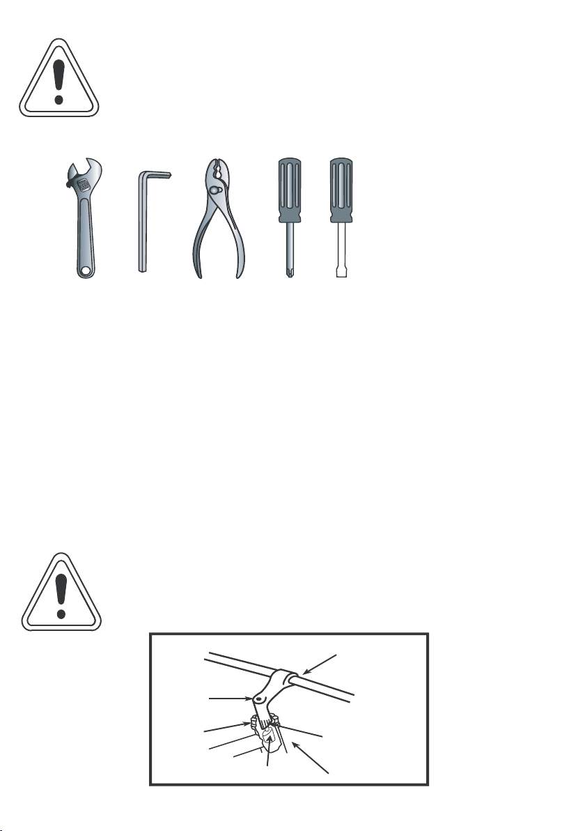
This is the WARNING symbol. It is used throughout this
manual to preceed safety instructions. Make sure you and
your child understand these instructions. Failure to do so
may result in your child losing control and falling. As any fall
has the potential to result in serious injury or death please pay
particular attention to these warnings. If you are unsure of any aspect of
these warnings you should consult a qualified bicycle technician before
using this product.
Congratulations on your purchase of this MooreLarge child’s bicycle.
Cycling is an excellent way for children to get some of the daily exercise
they need to keep healthy. It is also a fun way of teaching young children
valuable skills such as mobility, independence, balance, judgment and
self-confidence.
Once learned, these are skills that will last a lifetime
The most important part of fun cycling is to learn to do it safely.
IMPORTANT INFORMATION FOR PARENTS.
This manual has been written to help you maximise your child’s safety,
comfort and enjoyment whilst cycling. It is important that you and your
child understand the bike’s operations, limits and features to ensure
that your child enjoys safe cycling from the very first ride.
Rules for Children
To avoid accidents, teach children good riding skills with an emphasis on safety from an early age.
Children should be supervised by an adult.
1. Always wear a properly fitted helmet.
2. Do not play in driveways or the road.
3. Do not ride on busy streets.
4. Do not ride at night.
5. Be aware of other road vehicles behind and nearby.
6. Before entering a street: Stop, look right, left, and right again for traffic. If there's no traffic,
proceed into the roadway.
7. If riding downhill, be extra careful. Slow down using the brakes and maintain control of the steering.
8. Never take your hands off the handlebars, or your feet off the pedals when riding downhill.
The riding of small wheel diameter bicycles at excessive speeds can lead to instability and
is not recommended.Children should be made aware of all possible riding hazards and correct
riding behavior before they take to the streets. - Do not leave it up to trial and error.
-i-

1
Contents
Important information for parents ..............................................
Rules for children ...............................................................................
What it’s called ....................................................................................
Before you start...................................................................................
Helmets..................................................................................................
Assembly Tools required ............................................................
Getting started....................................................................................
Handlebars ...........................................................................................
Saddle and seat post.........................................................................
Pedals .....................................................................................................
Front wheel .........................................................................................
Training wheels ..................................................................................
Stabilizer safety ...................................................................................
Riding position Saddle height ...................................................
Handlebar height...............................................................................
Reach ......................................................................................................
Safety checklist ...................................................................................
Bicycle care ..........................................................................................
Basic maintenance ............................................................................
Storage...................................................................................................
Security .................................................................................................
Brake safety ..........................................................................................
Brake adjustment ..............................................................................
Brake cables .........................................................................................
Forks .......................................................................................................
Headset ..................................................................................................
Chain .......................................................................................................
Saddle and seat post.........................................................................
Tyres .......................................................................................................
Lubrication schedule ........................................................................
Service checklist..................................................................................
Torque settings...................................................................................
i
i
2
3
3
4
4
4
5
5
6
6
7
9
9
9
10
11
11
11
11
12
13
14
15
15
16
17
18
19
20
21

saddle
seatpost
seat binder bolt
rear brake
chain
top tube
chain ring
crank arm
pedal
tyre
handlebar grip
handlebar
brakelever
head tube
front brake
fork
rim
spokes
2
What it’s called

Before you start
CORRECT FITTING - MAKE
SURE YOUR HELMET COVERS
YOUR FOREHEAD.
INCORRECT FITTING. FOREHEAD
IS EXPOSED AND VULNERABLE
TO SERIOUS INJURY.
3
This bicycle is a child’s play cycle. It is designed for use by children aged 3
and over up to a maximum weight of 18kg. The maximum permissible weight
(cycle+ child) is 30kg. It is not designed to carry luggage or any other loads.
It is designed to be used by one child at a time and is for light recreational use
only. It has not been made to withstand the rigours of stunting, jumping or
competitive cycling.
It is not designed for use on roads and highways.
It is intended for supervised use by your child on safe pavements, parks and
paths.
Whatever style of bicycle they ride, children should sit more upright than adults. This helps
develop spatial awareness and encourages children to look in the direction they are travelling.
standover height. This is the distance between the top of the
top tube (at a point half way between the saddle and the handlebar stem) and the ground.
Your child’s inside leg measurement, when wearing shoes, should be at least 5cm greater than
this distance.
If it is not, the cycle is too big for your child and should not be ridden.
too small for the rider will be uncomfortable to ride and hard to
control and fall.
Whilst it may not be a legal requirement, we strongly recommend
all riders (especially young children) wear a bicycle helmet whilst
cycling. Any bicycle helmet should be CE approved and meet the
requirements of EN1078.
Most serious bicycle injuries involve head injuries that may have
been less severe if the rider had worn a helmet. A helmet must
purpose. Please refer to the owner’s manual provided with your
helmet for further instruction.

Adjustable spanner
Allen keys (provided)
Pliers with cable cutting ability
Philips head screwdriver
Square-bladed screwdriver
Tools required
Getting started
Open the carton from the top and remove the bicycle. Remove the straps and protective
wrapping from the bicycle. Inspect the bicycle and all accessories and parts for possible
shortages. It is recommended that the threads and all moving parts in the parts package be
lubricated prior to installation. Do not discard packing materials until assembly is complete to
ensure that no required parts are accidentally discarded.
Handlebars
Remove the protective cap from the stem wedge and loosen the stem bolt using the Allen key.
Some models may use a hexagonal bolt instead of an Allen key bolt.
Place the handlebar stem into the head tube, observing the minimum insertion mark on the
handlebar stem and ensuring that all cables are free of tangles.
Check that the fork and the handlebar are facing forward, and that they are properly aligned
with the front wheel.
Tighten the stem bolt 2 turns. Rotate the handlebar to the desired position in relation to the
front wheel.
Tighten stem bolt until the bar is fully secured. Check that the stem binder bolt is tight and secure.
The handlebar must be inserted so that the minimum insertion
mark cannot be seen. Over tightening the stem bolt or
headset assembly may cause damage to the bicycle
and/or injury to the rider.
Assembly
Minimum Insertion
Marks
Stem Bolt
Head T ube
Binder Bolt
Top Nut
W edge
It is recommend that you consult a bicycle specialist if you have
ANY doubts or concerns as to your experience or ability to
properly assemble, repair, or maintain your bicycle.
4

Attachment of an incorrect pedal into a crank arm will
cause irreparable damage.
Pedals
Saddle and seat post
To avoid damage to either the seat post, the frame
or possibly the rider, the minimum insertion mark
must be inside the frame to such an extent it cannot be seen.
Seat Post
Binder Bolt
Minimum Insertion
Line
5
Loosen nut on the seat post binder bolt
and add 3 or 4 drops of oil onto the
threads of the bolt. Thread the nut on the
seat post binder bolt loosely. Insert the seat
post into the seat tube of the bicycle frame
observing the minimum insertion mark on
the seat post.
Position the top surface of the seat parallel
with the ground.
Securely tighten the bolts on the seat post
binder bolt.
Look for the letters “R” for right, and “L” for left,
stamped on each pedal spindle. Start each pedal
spindle by hand to avoid stripping the threads.
Tighten with a spanner. Note that the right hand
pedal attaches to the chainwheel side crank arm
with a right-hand (clockwise) thread. The left
pedal attaches to the other crank arm and has a
left-hand (counter-clockwise) thread. It is very
important that you check the crank set for correct
adjustment and tightness before riding your bicycle.
Once the pedals have been attached, check that the
crank arm rotates smoothly and that there is no
lateral movement.

Axle Nut
Axle Hub
Cone Nuts
Fork Drop Out
Retaining
Washer
p
e
t
S
g
n
i
n
i
a
t
e
R
r
e
h
s
a
W
t
u
n
x
e
H
r
e
h
s
a
W
l
e
e
h
w
g
n
i
n
i
a
r
T
Should t
l
o
b
r
e
e
c
a
r
b
l
e
e
h
W
Front wheel
6
1. Make sure the brakes are loose enough to allow the wheel to pass through the brake pads
easily.
2. Place wheel into fork drop outs.
3. Install retaining washers with raised lip pointed towards the fork and insert into the small
hole of the fork blade. NOTE: ehtfoecalpnisrehsawgniniaterpetsevahyamsekibemoS
retaining washer (shown in dotted box). If so, install the step retaining washer, raised
portion sliding in to the fork dropouts.
4. Install axle nut and tighten. Make sure the wheel is centered between the fork blades.
5. Spin the wheel to make sure that it is centered and clears the brake shoes. Tighten the
brakes if necessary.
It is very important to check the front wheel connection to the
bicycle. Failure to properly tighten may cause the front wheel
to dislodge.
Training wheels
First attach the training wheels to the wheel brace. Insert the shoulder bolt through the wheel.
on the shoulder bolt. Lock the training wheel into place by screwing another hex nut onto the
shoulder bolt. Repeat for both training wheels.

C-Shape
7
It is very important to check the training wheel connection
to the bicycle. Failure to properly tighten may cause the
training wheel to dislodge and cause the child to lose
control and fall.
Training wheels should be checked before every use to
not over-worn, cracked or otherwise damaged.
Damaged training wheels should be replaced before
any future use.
Attaching training wheel brace to bicycle
Remove the axle nut and washer from the rear wheel axle. Place the brace stabilizer washer
out. Next, place the C-shaped wheel brace onto the axle and replace the washer and axle nut.
Tighten the axle nut securely, making sure that the wheel brace stays in the proper vertical
position. The elongated hole on the wheel brace allows the training wheel height to be
It is important that any child using stabilisers is fully
supervised. As they provide extra width, more contact
surfaces with the ground and are behind the child, they can
increase the risk of a collision, especially on uneven ground.
Any collision can render the bicycle unsafe and can lead to
the child losing control and falling.
Brace stabilizer
washer
c-shaped
wheel brace
Axle nut
Inner axle
Training wheel
Inner axle nut
DO NOT
REMOVE

This bicycle is supplied with one front (white), one rear (red) two wheel (white) and four
and mountings for signs of wear or damage. If damage is found, replace immediately.
First insert one washer onto the hex bolt and insert hex bolt through the
onto the bolt and thread a hex nut onto the bolt behind the fork.
position. See diagram to the right.
see the top diagram. Next, remove the clamp screw and open the
the handlebar or seatpost. If the clamp is too loose,
insert the shim inside of the clamp. Tighten the
see the diagram below. Finally, adjust the
is upright and facing away from the bike.
8

Riding position
Saddle height
Arms not over-
extended
Handlebar stem
height about
the same as
seat height
Pedal at
bottom position
Handlebar height
Handlebar
Binder Bolt
Exceeds 2 1/2”
(64mm)
Reach
To obtain maximum comfort, the rider should not
overextend his or her reach when riding.
9
In order to obtain the most comfortable riding position and
should be set correctly in relation to the rider’s leg length.
The correct saddle height should not allow leg strain from
over-extension and the hips shoud not rock from side to side
when pedalling. While sitting on the bicycle with one pedal
at its lowest point, place the ball of the foot on that pedal.
The correct saddle height will allow the knee to be slightly
bent in this position. If the rider then places the heel of that
foot on the pedal, the leg should be almost straight.
Under no circumstances should the seat post
project from the frame beyond its “Minimum
Insertion” mark. If your seat post projects from
the frame beyond these markings, the seatpost or
frame may break which could cause the rider to
lose control and fall. Prior to each ride
ensure the saddle tightening mechanism are
properly adjusted. A loose saddle clamp or seat
post binder can cause damage to the cycle and
can cause the rider to lose control and fall.
Maximum comfort is usually obtained when the handlebar
height is equal to the height of the seat. You may wish to try
The stem’s “Minimum Insertion” mark must not
be visible above the top of the headset. If the
stem is extended beyond this mark, the stem
may break or damage the fork’s steerer tube,
which could cause you to lose control and fall.
Failure to properly tighten the stem binder bolt,
the handlebar binder bolt, or the bar end
extension clamping bolts may compromise the
steering action which could cause you to lose
control and fall. Place the front wheel of the
bicycle between your legs and attempt to twist
the handlebar/stem assembly using a reasonable amount of force. If you can
twist the stem in relation to the front wheel, turn the handlebars in relation to
the stem, or turn the bar and extensions in relation to the handlebar, you must
tighten the appropriate bolts accordingly.
Minimum Insertion M ark
(should not be visibl e)
Stem wedge
bolt
Max imum Height/
Mini mum Insertion
Mark

1. Brakes
- Ensure front and rear brakes work properly.
- Ensure brake shoe pads are not over worn and are correctly positioned in relation to the rims.
- Ensure brake control cables are lubricated, correctly adjusted and display no obvious wear.
- Ensure brake control levers are lubricated and tightly secured to the handlebar.
2. Wheels and tyres
tyre sidewall.
- Ensure tyres have tread and have no bulges or excessive wear.
- Ensure rims run true and have no obvious wobbles or kinks.
- Ensure all wheel spokes are tight and not broken.
- Check that axle nuts are tight.
3. Steering
- Ensure handlebar and stem are correctly adjusted and tightened, and allow proper steering.
- Ensure that the handlebars are set correctly in relation to the forks and the direction of travel.
- Check that the headset locking mechanism is properly adjusted and tightened.
4. Chain
- Ensure chain is oiled, clean and runs smoothly.
- Extra care is required in wet or dusty conditions.
5. Bearings
- Ensure all bearings are lubricated, run freely and display no excess movement, grinding
or rattling.
6. Cranks and pedals
- Ensure pedals are securely tightened to the cranks.
- Ensure cranks are securely tightened to the axle and are not bent.
7. Frame and Fork
- Check that the frame and fork are not bent or broken.
- If either are bent or broken, they should be replaced.
8. Accessories
- Ensure the rider is wearing a helmet.
10
SAFETY CHECKLIST
Before every ride, it is important to carry out the following safety checks:

Storage
Keep your bicycle in a dry location away from the weather and the
sun. Ultraviolet rays may cause paint to fade or rubber and plastic
parts to crack. Before storing your bicycle for a long period of time,
paint. Don't cover with plastic as "sweating” will result which may
cause rusting.
Security
It is advisable that the following steps be taken to prepare for and
help prevent possible theft.
1. Maintain a record of the bicycle’s serial number, generally located
on the frame underneath the bottom bracket.
2. Register the bicycle with the local police.
3. Invest in a high quality bicycle lock that will resist hack saws and
bolt cutters. Always lock your bicycle to an immovable object if it
is left unattended.
11
Bicycle care
Basic maintenance
The following procedures will help you maintain your bicycle for years of enjoyable riding. For
painted frames, dust the surface and remove any loose dirt with a dry cloth. To clean, wipe
with a damp cloth soaked in a mild detergent mixture. Dry with a cloth and polish with car or
furniture wax. Use soap and water to clean plastic parts and rubber tyres. Chrome plated
Avoid leaving it in the rain or exposed to corrosive materials.Riding on the beach or in coastal
areas exposes your bicycle to salt which is very corrosive. Wash your bicycle frequently and
wipe or spray all unpainted parts with an anti-rust treatment. Make sure wheel rims are dry so
This will prevent accelerated bearing deterioration.If paint has become scratched or chipped
to the metal, use touch up paint to prevent rust. Clear nail polish can also be used as a
preventative measure. Regularly clean and lubricate all moving parts, tighten components and
make adjustments as required. The use of BED, SATIN and TITANIUM surface treatments
minimizes the number of places where rust can surface. Over a period of time, components
will wear out and need replacing. This is quite normal and is not covered by any guarantee or
warranty. When replacing components, it is of paramount importance that only good quality,
the safety of your child and will shorten the life of the bicycle.

Wet Weather
IT IS RECOMMENDED TO NOT RIDE IN WET WEATHER
In wet weather you need to take extra care. Brake earlier, you will take a
longer distance to stop.
Decrease your riding speed, avoid sudden braking and take corners with
additional caution.
Pot holes and slippery surfaces such as line markings and train tracks
all become more hazardous when wet.
Moisture or dirt on the brake shoes reduces their ability to grip.
Brakes
Teach your child to brake properly so that he/she is ready to stop quickly in an
emergency. The front brake can provide much greater stopping power than the
rear brake, but jamming on the front brake too hard in an emergency can lift the
rear wheel and throw the child over the handlebars.
Have him/her practice applying the front brake hard, but not so hard that the
rear wheel starts to lift or skid.
Braking on slippery surfaces, curves, and steep downgrades requires additional skill and care.
The way to maintain control on loose or wet surfaces is to go more slowly
to begin with.
12
the rear brake and the right hand lever operates the front brake.
The correct adjustment and operation of these brakes is extremely important for safe operation
and control of the bicycle. The rider should fully understand their brakes and be capable of
before every ride.
Frequent checking and adjustment is necessary as the control cables will stretch and the brake
pads will become worn with use.
Never ride a bicycle unless the brakes are functioning properly.
Inspection
Brake levers should be checked for tightness at least every three months. They should be set in
a comfortable position within easy reach of the rider's hands, and must not be able to move
on the handlebar. Some brake levers make use of a reach adjustment screw, which can be
altered to the distance between the handlebar grip and the lever, as required.
The brake pads should be checked for correct positioning and tightness before every ride and
the various bolts and nuts at least every three months.
Squeeze each brake lever to make sure they operate freely and that the brake pads press hard
enough on the rims to stop the bike.
There should be about 1mm - 2mm clearance between each pad and the rim when the brakes
are not applied. The brake pads must be properly centered for maximum contact with the rim.
Replace the brake pads if they are over worn so that the grooves or pattern cannot be seen.
The brake cable wires should be checked for kinks, rust, broken strands or frayed ends.
The outer casing should also be checked for kinks, stretched coils and other damage. If the
cables are damaged, they should be replaced.

Side Pull
Brakes
When assembling or adjusting the brakes, make
sure the cable anchor is tight. Failure to securely
tighten the nut could result in brake failure and
personal injury.
Cable
Adjusting
Barrel
Center Bolt
Cable
Anchor
Nut
Brake Shoe
Fixing Nut
in Back
Brake
Arm
Loosen the cable anchor nut and thread the brake cable through it.
Tighten the nut by hand until it holds the cable in place.
Squeeze the brake arms together against the rim of the wheel.
Loosen the nuts on the brake shoes and turn until they match the angle of the rim.
Tighten the nuts securely.
Pull down on the end of the brake cable with pliers, hold taut and securely tighten the
cable anchor nut.
Spin the wheel, the brake shoes should not contact the rim at any point and should be an
equal distance from the rim on both sides.
Make sure all nuts and bolts are securely tightened.
13
Brake adjustment

Cables and cable housing
Cables and housing are one of the most over-looked parts on the bicycle.
pressure needed to operate the brakes. Before every rid e, check that there are no kinks or frays
in the cables and housing. Also check that the housing is seated properly into each cable
stop of the bicycle.
Do not ride a bicycle that is not operating properly.
ki
n
k
f
ray
goo
d
ca
bl
e
Depress the brake lever about 10 times as
far as the grip and check that everything is
operating correctly and that the shoe clear ance
is correct before using the brakes.
14

Forks
(Figure 1) consisting of stationary tubing with curved blades.
The other type is a suspension fork (Figure 2) consisting of stanchion tubes riding on elastomers or
adjustable.
Do not attempt to disassemble a suspension fork yourself. Consult a professional
bicycle technician should you have any problems.
Check the tightness of the headset and the fork. Rotate the fork checking for smoothness.
If it feels like the fork is binding, then an adjustment will need to be made to the headset. Move the
fork in a push/pull manner checking for tightness. If any play is detected, loosen the top nut, adjust the
bearing cup, and retighten the top nut. Recheck the rotation and tightness. If necessary, readjust until a
smooth rotation is achieved without backward or forward movement. If your bike is equipped with a
suspension fork, check that the fork compresses and rebounds smoothly. To do this, place the fork
dropouts against the ground, push and release the handlebar. The fork will generally compress 2-5cm
and rebound quickly. Most elastomer type forks will gradually soften with use.
Steering Tube
Crown
Brake Boss
Blade
Drop-out
1.
Steering Tube
Brake Boss
Fork Blade
Drop-out
Brake Bridge
Crown
2.
Headset
Inspection
The headset bearing adjustment should be checked every month.
This is important as it is the headset which locks the fork into the
frame, and if loose, can cause damage or result in an accident.
While standing over the frame top tube with both feet on the ground,
detect any looseness in the headset, it will need adjustment. Check
that the headset is not over tight by slowly rotating the fork to the right
and left. If the fork tends to stick or bind at any point, the bearings
are too tight.
Adjustment
Loosen the headset top locknut or remove it completely along with the
lock nut using a suitable wrench.
Note: Do not over tighten or bearing damage will occur.
Lock Nut
Lock Washer
Adjusting Cup/Cone
Ball Retainer
Top Head Cup
Bottom Head Cup
Ball Retainer
Crown Race
Always make sure that the headset is properly
adjusted and that the headset locknut is fully
tightened before riding.
Over tightening the stem bolt or headset
assembly may cause damage to the bicycle
and/or injury to the rider.
Standard Headse t
15

Chain
Inspection
The chain must be kept clean, rust free and frequently lubricated in order to extend its life as
long as possible. It will require replacement if it stretches or breaks. Make sure that there are
Lubrication
The chain should be lubricated with light oil at least every month, or after use in wet, muddy,
braking surfaces.
Adjustment and replacement
To adjust the chain:
1. Loosen the rear axle nuts and move the wheel forward to loosen, or backward to tighten.
2. When correctly adjusted, the chain should have approximately 10mm of vertical movement
when checked in the centre between the chainwheel and rear sprocket.
Centre the wheel in the frame and re-tighten the axle nuts after any adjustment.
Bicycles which have a single speed freewheel, generally use a wider chain than derailleur
geared bicycles. These chains can generally be disconnected by way of a special U-shape
of the chain, position the master link side plate, and slip on the U-shaped snap-on plate.
Make sure the open end of the U-shaped plate is trailing as the link approaches the chainwheel
when pedaling forward.
Straightedge
10 mm
Rear Sprocket Front Chainwheel
Pull up
Master link
Master link
side plate
Snap on
plate
16

Inspection
adjustment every month. On removing the seat post from the frame, you will notice a mark
about 65mm up from the bottom with the words or “minimum insertion”. To avoid damage
to either the seat post, the frame or possibly the rider, the minimum insertion
mark must be inside the frame.
Lubrication
gr ease, rust or dirt. T hen apply a thin
to the fra me. Re-insert, adjust and tighten
the seat post in the frame.
Seat Clamp Nut
Standard
Seat Post
Seat Post
Binder Bolt
17
Saddle and seat post
Adjustment
The seat can be adjusted in height, angle and distance from the handlebars to suit the
individual rider. Saddle angle is a matter of personal preference but the most comfortable
position will usually be found when the top of the seat is almost parallel to the ground, or
slightly raised at the front.
The saddle can also be adjusted by sliding it forward or back along the mounting rails to
the clamp under the seat and place it in the frame without tightening. Adjust it to the desired
position on the post, adjust the height to the required level and tighten the binder bolt. Test the
security by grasping the seat and trying to turn it sideways. If it moves, you will need to further
tighten the binder bolt.
Remember that the minimum insertion mark must remain inside the frame assembly.

Tyre Inspection
Tyres must be maintained properly to ensure road holding and stability. Check the following areas:
tyre gauge and a hand pump r ather than a service station pump . Caution: Using a sevice
dangerous and is not recommended.
Tread:
other damage. Caution: Excessively worn or damaged tyres should be replaced.
Valves:
If you need to repair a tyre, follow these steps:
1. Remove the wheel from the bicycle.
Loosen the tyre bead by pushing it inward all the way around.
3. Press one side of the tyre bead up over the edge of the rim.
Note: Use tyre levers, not a screwdriver, otherwise you may damage the rim.
4. Remove the tube, leaving the tyre on the rim.
5. Locate the leaks and patch using a puncture repair kit following the instructions carefully, or
alternatively, replace the tube. Note: Ensure that the replacement tube size matches the
size stated on the tyre sidewall and that the valve is the correct type for your bicycle.
6. Match the position of the leak in the tube with the tyre to locate the possible cause and
mark the location on the tyre.
Inspect the inside of the rim to ensure there are no protruding spokes, rust or other
potential causes.
8. Remount one side of the tyre onto the rim.
10. Place the valve stem through the hole in the rim and work the tube into the tyre.
11. Using your hands only, remount the other side of the tyre by pushing the edge toward
the centre of the rim. Start on either side of the valve and work around.
12. Before the tyre is completely mounted, push the valve up into the rim to make sure the tyre
can sit squarely in position.
14. Check that the tube is not caught between the rim and the tyre bead at any point.
16. Replace the wheel into the frame.
Tyres
18
This manual suits for next models
5
Table of contents
Popular Bicycle manuals by other brands

Schindelhauer Bikes
Schindelhauer Bikes Viktor manual

HP Velotechnik
HP Velotechnik Street Machine Gte 2008 Operating manual and service instructions

Milly Mally
Milly Mally hero Operational manual

Otto
Otto FLYING PIGEON user manual

TRYBIKE
TRYBIKE High Bicycle User instructions

Scott
Scott SPARK owner's manual