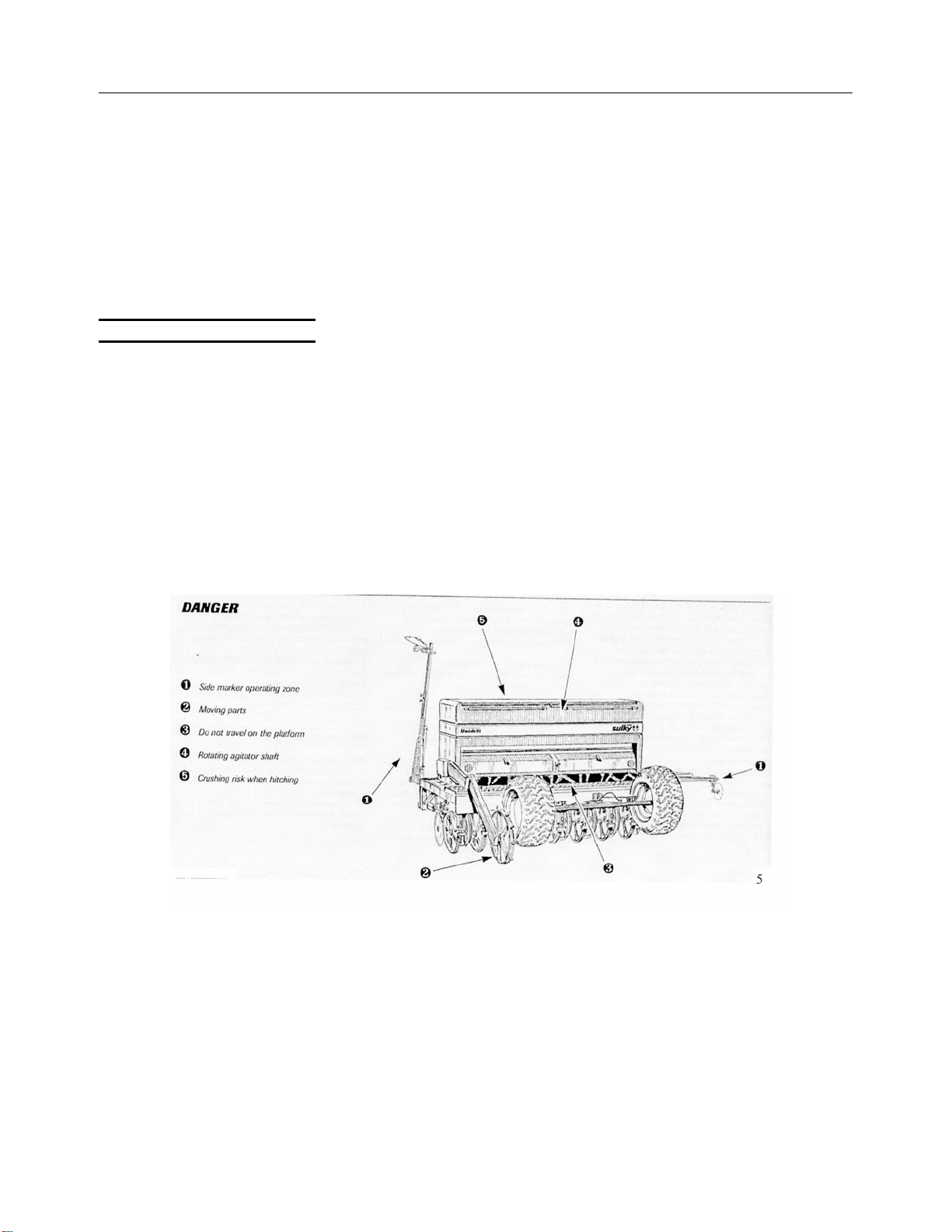
Safety / Instruction Decals
6
the ignition and wait until all
moving parts have come to a
standstill.
26 – Do not stand between the
tractor and the machine until the
handbrake has been applied
and/or the wheels have been
wedged.
27 – Before any operation on the
machine, ensure that it cannot be
started up accidentally.
28 – Do not use the lifting ring to
lift the machine when it is loaded.
PROPER USE OF THE
MACHINE
The seed drill must only be used
for tasks for which it has been
designed. The manufacturer will
not be liable for any damage
caused by using the machine for
applications other than those
specified by the manufacturer.
Using the machine for purposes
other than those originally
intended will be done so entirely
at the user’s risk. Proper use of
the machine also implies:
- complying with instructions on
use, care and maintenance
provided by the manufacturer;
- using only original or
manufacturer recommended
spare parts, equipment and
accessories.
The seed drill must only be
operated, maintained and
repaired by competent persons,
familiar with the specifications and
methods of operation of the
machine. These persons must
also be informed of the dangers to
which they may be exposed.
The user must strictly abide by
current legislation regarding:
- accident prevention
- safety at work (Health and
Safety Regulations)
- transport on public roads (Road
Traffic Regulations).
Strict compliance with warnings
affixed to the machine is
obligatory.
The owner of the equipment shall
become liable for any damage
resulting from alterations made to
the machine by the user or any
other person, without the prior
written consent of the
manufacturer.
HITCHING
1– When hitching or unhitching
the machine form the tractor,
place the control lever of the
hydraulic lift in such a position
that the lifting mechanism cannot
be activated accidentally.
2 – When hitching the machine to
the three-point-lifting mechanism
of the tractor, ensure that the
diameters of the pins or gudgeons
correspond to the diameter of the
tractor ball joints.
3 – Caution! In the three-point
lifting zone, there may be a
danger of crushing and shearing
4 – Do not stand between the
tractor and the machine whilst
operating the external lift control
lever.
5– When in transport, lifting
mechanism stabilizer bars must
be fitted to the machine to avoid
floating and side movement.
6– When transporting the
machine in the raised position,
lock the lift control lever.
DRIVE EQUIPMENT
(Power take-off and universal
drive shafts)
1– Only use universal drive
shafts supplied with the machine
of recommended by the
manufacturer.
2– Power take-off and universal
drive shaft guards must always be
fitted and in good condition.
3 – Ensure that the tubes of the
universal drive shafts are properly
guarded, both in the working
position and in the transport
position.
4– Before connecting or
disconnecting a universal drive
shaft, disengage the power take-
off, turn off the engine and re-
move the key from the ignition.
5– If the primary universal drive
shaft is fitted with a torque limiter
or a free wheel, these must be
mounted on the machine power
take-off.
6– Always ensure that universal
drive shafts are fitted and locked
correctly.
7– Always ensure that universal
drive shaft guards are
immobilized in rotation using the
specially provided chains.
8– Before engaging power take-
off ensure that the speed selected
and the direction of rotation of the
power take-off, comply with the
manufacturer’s instructions.
9 – Before engaging power take-
off, ensure that no persons or
animals are close to the machine.
10 – Disengage power take-off
when the universal drive shaft
angle limits laid down by the
manufacturer are in danger of
being exceeded.
11 – Caution! When power take-
off has been disengaged, moving
parts may continue to rotate for a
few moments. Do not approach
until they have reached a
complete standstill.
12 – On removal from the
machine, rest the universal drive
shafts on the specially provided
supports.
13 – After disconnecting the
universal drive shafts from the
power take-off, the protective cap
should be fitted to the power take-
off.
14 – Damaged power take-off and
universal drive shaft guards must
be replaced immediately.
HYDRAULIC CIRCUIT
1– Caution! The hydraulic circuit
is pressurized.
2– When fitting hydraulic motors
or cylinders, ensure that the
circuits are connected correctly in
accordance with the
manufacturer’s guidelines.
3– Before fitting a hose to the
tractor’s hydraulic circuit, ensure
that the tractor-side and machine-
side circuits are not pressurized.
4– The user of the machine is
strongly recommended to identify
the hydraulic couplings between
the tractor and the machine in
order to avoid wrong connection.
Caution! There is a danger of
reversing the functions (for
example: raise/lower).
5– Check hydraulic hoses once a
year, for:
- Damage to the outer surface
- Porosity of the outer surface
- Deformation with and without
pressure
- State of the fittings and seals
The maximum working life for
hoses is 6 years. When replacing
them, ensure that only hoses with
the specifications and grade
recommended by the machine
manufacturer are used.
6– When a leak is found, all
necessary precautions should be
taken to avoid accidents.