Moore Unidrill-W Series User manual

1
August 1999

Dear Customer
Thank you for purchasing a MOORE UNIDRILL and for showing
confidence in our product.
For effective use, and to benefit from all the features of our drill,
we recommend that you read this document very carefully.
From your experience, please do not hesitate to inform us of
your comments and suggestions, which will always be useful to
us in improving our products.
We wish you success with your drill.
Assuring you of our best attention at all times.
Sam Moore
Managing Director
33 Kirk Road, Ballymoney, Co. Antrim, N. Ireland
Tel: Ballymoney (012656 64444) Fax : (012656 65696)
2

Moore Uni Drill Limited
33 Kirk Road , Ballymoney,
Co. Antrim , N. Ireland, BT53 6PP
Tel : (0044) 12656 64444
Fax (0044) 12656 65696
Machine Width :
Serial Number :
Customer Name :
Address :
Tel:
Mobile No :
E. mail : Post Code :
I HAVE RECEIVED THE ABOVE MACHINE IN AN ACCEPTIBLE
CONDITION AND TO THE CORRECT SPECIFICATION.
I HAVE RECEIVED AND READ THE OWNERS MANUAL FOR
SAFE AND CORRECT OPERATION OF MACHINE.
I WISH TO REGISTER MY MACHINE FOR WARRANTY.
SIGNED :- CUSTOMER DATE : -
1. To be completed , detached and returned to Moore Uni Drill
within 14 days of customer receipt / purchase.
2. It is essential that all details be completed.
3. Failure to complete and return this form will prevent claim
settlement.
3

Declaration of Conformity
Moore Uni Drill Limited,
Of 33 Kirk Road, Ballymoney, Co. Antrim, N. Ireland. BT53 6PP
hereby declare that
Model ………………………………
Serial No …………………………..
Date ………………………………..
conforms with the following Directives and Regulations, and has
been certified accordingly.
The supply of Machinery (Safety) Regulations 1992
( S.I. 1992/ 3073)
The Provision and Use of Work Equipment Regulations 1992
( S.I. 1992/2932)
Certified on behalf of Moore Uni Drill Limited
James A O’ Kane
Technical Director
4

5

CONTENTS
SPECIFICATIONS
ADDITIONAL GENERAL SAFETY RULES
HITCHING
TRANSPORT
DEPTH CONTROL
STANDARD CONTROL SYSTEM
HEAD LAND CONTROL SYSTEM
ROGER SEEDBOX, FAN UNIT
FAN SPEED
CHECKING COULTERS
ROGER HOPPER CALIBRATION
CALIBRATION TEST
MAINTENANCE OF SEEDHOPPER
MAINTENANCE (Additional to main instruction book)
PROBLEM SOLVING
SUPPLEMENT TO MAIN PARTS LIST
6

SPECIFICATIONS
Moore Unidrill 4m HP
•· Width of work 4m
•· Transport Width. 3m
•· Seedbox capacity 1600L (Roger)
•· Row width 16.6 cm
•· No of Rows 24
•· Horsepower required 120 H.P
•· Weight 3400 kg
•· Transport Height 3.5 m
•· Tyres 500 x 50 x 17
Options:
•Bogie axles
(For extreme wet / cloddy / stony / trashy conditions)
•Stepped Pneumatic Tyres
•Hydraulic brakes
•Air brakes
•Head Land Control system
7

SPECIFICATIONS
Moore Unidrill 6m HP
•· Width of work 6m
•· Transport Width. 3m
•· Seedbox capacity 2200L
•· Row width 16.6 cm
•· No of Rows 36
•· Horsepower required 160 H.P
•· Weight 5100 kg
•· Transport Height 4.5 m
•· Tyres 550 x 45 x 22.5
Options:
•Bogie axles
(For extreme wet / cloddy / stony / trashy conditions)
•Stepped pneumatic tyres
•Hydraulic brakes
•Air brakes
•Head Land Control system
8

ADDITIONAL GENERAL SAFETY RULES
(SUPPLEMENT TO MAIN INSTRUCTION BOOK)
1. Additional care must be taken with H.P. Drills due to the increased
transport height. Good driving sense in avoiding low obstacles
especially overhead power lines and cables, bridges, trees and other
factors which may effect transport and use of H.P. Drills.
2. Always unfold H.P. Drills in raised position with transport pins
engaged and mechanical wing locks dis – engaded trying to
unfold wings whilst transport locks are still engaged can damage
main frame.
3. Always transport H.P. Drills with hopper empty, and do not exceed
25km/h.
4. Never operate bout markers unless area is clear.
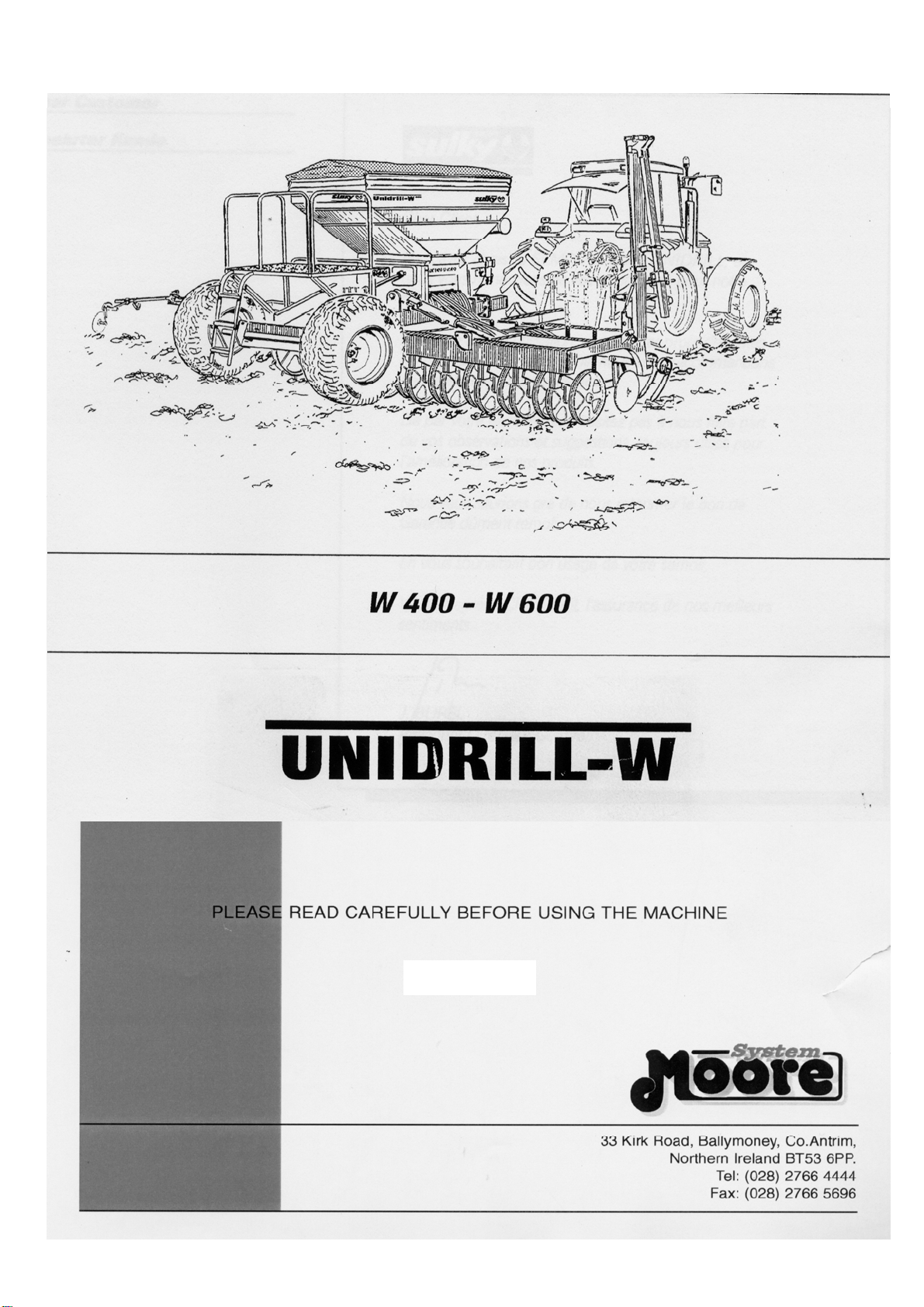
HITCHING
1. Attach tractor to drill using pick up hitch or clevis.
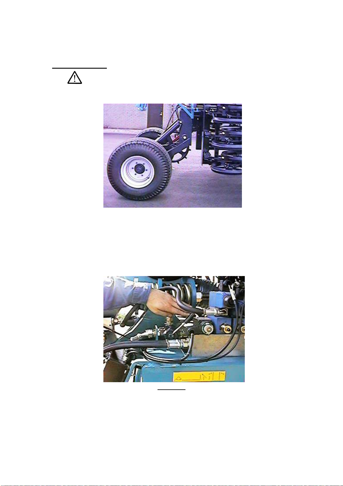
2. Attach the pipes of the hydraulic fan to the tractors priority valve (if
fitted) a cap fitted with a chain identifies the pressure hose.
The return hose must have unrestricted return access to hydraulic tank
(i.e ‘dump valve’), otherwise damage may occur . If in doubt refer to your
tractor supplier.
3. Attach the hoses for the Head Land Control (HLC) system, Must be
fitted to double acting spool.
4. Connect HLC hand grip onto the spool lever that is being used to run
HLC system.
5. Connect HLC hand grip cable to the cable from the HLC control box.
6. Connect the other cable from the HLC control box to the tractors
standard 12V power source.
7. Connect the cable from the tram – lining system to the tractors 12V
Supply.
8. Connect lighting cables and braking hoses to the appropriate places.
9

TRANSPORT
Road to Work.
1. Ensure that the drill is in an open and clear area.
2. Lift the drill fully and insert the transport pins on the axle unit, Figure A
Figure A
3. Extend the depth control ram to its maximum.
4. Change the manual divertor valve from the marker to the wings ;
Lever towards the rear engages the wings, see Figure B
Figure B
10

Lever toward the front engages the markers, see figure C
Figure C
5. Dis – engage the wing locks as shown in figure D
Figure D
6. Operate the hydraulics to unfold the wings.
7. Pressure the wings down, i.e allow time to purge air from the system.
8. Change the manual divertor valve from wings back to the markers.
9. Operate hydraulics to raise drill from transport position and remove
axle transport pins.
10. Machine is ready for work.
11

Note : it is advisable during the working day to check that the centre
section is drilling at the same depth as the wings, if not repressurise the wings
from time to time. This means that the manual divertor valve must be put
back from markers to wings and vice versa.
Work to Road
1. Ensure the drill is clear of all obstacles when folding the wings.
2. Change manual divertor valve to wings and engage mechanical wing
locks.
3. Ensure hopper is empty, and both markers are raised.
4. Raise drill to transport position and insert transport pins.
5. Lower drill onto transport pins.
6. Fully extend depth control ram.
7. Operate the hydraulics to fold the wings.
8. The drill is now ready to transport.
Note When transporting drill always press
button 5 on Head Land Control Joystick to
de – activate electro – hydraulic system
See also Head Land Control
Standard Head Land System
12

1234
Standard Joystick
1 = Markers
2 = Draw bar
3 = Axle unit
4 = Auxilary
Figure D
Shown in Figure D is a schematic sketch of the standard hand
grip.
The system uses a single double acting service to provide
individual or sequenced control over all functions of the drill. The
operation is as follows:- press a button to move a cylinder and
simultaneously operate the tractors double acting control valve to
and fro’ to achieve the desired cylinder movement.
Press Button 1 and this will operate the markers,
Press Button 2 and this will adjust the hydraulic draw bar,
Press Button 3 and this will operate the axle unit,
Press Button 4 and this will operate the auxiliary function i.e
levelling board.
With this system, functions can be “locked on” to help
automate a head land turn, i.e. push buttons 2 and 3 forward to
lock them on, then when going to do a head land turn, press
button one and pull the spool lever, this will bring in the markers,
raise the draw bar and lower the axle unit.
Whilst drilling, you may want to bring in a marker, without
lifting the drill switch off buttons 2 and 3, and just press button one
to bring in the markers.
13

Head Land Control
The system uses a single double acting service from the tractor to
provide individual or sequenced control over all functions of the
drill. The operation is as follows :- press a button to operate a
sequence or move a cylinder and simultaneously operate the
tractors double acting control valve to and fro’ to achieve the
desired cylinder movement.
The sequence for each button is listed below :-
Press button 1 – standard head land turn - operates the
markers first and ensures the rear axle moves before the draw bar,
thus dis – engaging the drive wheel.
14

Press button 2 – adjusts the memory cylinders internal stop
postion; this is best done on the ground. This controls drill depth.
Press button 3 – operates an auxiliary function where fitted, e.g
levelling board.
Press button 4 – operates the rear wheels only.
Press button 5 – turns the markers “off”. Therefore over – riding
the markers when doing head lands.
Press button 6- switches the markers back “on”.
Pulling the spool and not using any button operates the markers
only. Be careful not to pull the spool lever in transport as
either:
The wings will be activated ,
The markers will be activated ,
Additional safety can be gained by pressing button 5 before
road transport, the will dis engage the electro – hydraulic
system, unless one of the other buttons is pressed.
Depth Control
The depth control is controlled from the tractor cab, by operation of the spool
valve.
As previously mentioned in the transport section, the depth control is
controlled direct from the spool. Now you are ready to set the depth.
It is recommended that when starting to drill the depth should be set and
checked after a number of metres and adjusted to suit.
There is a colour scale on the depth control ram, which is clearly visible from
the tractor; this is to give guidance. When the correct depth has been
achieved, use the stroke control segments to maintain this depth through out
drilling. (On machines without HLC)
15

To prevent the ram from creeping one way or the other when in work or in
transport, they are fitted with Double Pilot Operated Check Valves.
Because it is hydraulically operated it may be adjusted on the move, hence
when in changeable conditions it is often required to exert more pressure
when going from light into heavy soils , and vice versa.
Memory cylinder
Using the same procedure as above, you can set the depth by using the
button marked Memory Cylinder Adjust on the Head Land Control Hand Grip,
this will maintain your drilling depth. Should you need to adjust the drill
through variable soils, always use this button.
See also Head Land Control system
W SEEDBOX
FAN UNIT
Hydraulically Driven Fan
1. The maximum oil flow required for the fan speed (2800 rpm) is about
26 litres / min.
2. The use of the fan requires the connection on a motor valve (see
tractor dealer) or single acting spool with dump facility to tank.
3. The hoses are equipped with a quick release coupling, the return must
be unrestricted as previously mentioned.
4. A cap fitted with a chain identifies the pressure hose. A one way
valve is located on the oil return hose in order to avoid damage to the
hydraulic motor.
5. A flow control valve is used to adjust the fan speed.
To increase fan speed, move the lever to the higher numbers on the
scale (1-10). To decrease the fan speed, move the lever the lower end
of the scale (10-1).
6. If the tractor used is fitted with a variable flow pump and integrated
control valve the flow valve, located on the drill, must be completely
open and the tractor’s valve must be used to adjust the fan speed. This
uses less tractor oil.
16

Use of the Hydraulically Driven Fan
1. Wait until the fan has reached its working speed before starting to drill.
2. The maximum fan speed is 3500 rpm. Beyond this speed damage is
probable.
3. By using the flow control valve it is possible to adjust the fan speed
and therefor the air flow from the fan according to the type of seed
being used.
Rape & Small Seeds. 1800 -2000 Rpm.
Wheat & Barley, in dry soil 2000 - 2200 Rpm
Peas & Beans 2200 - 2800 Rpm.
This is only a guide
Be aware to set the fan speed accordingly to avoid blowing the seed
back out of the soil, (especially in dry conditions).
4. Check the fan speed by using the multifunction control box.
Fan Speed
Before setting fan speed, run system at half throttle to warm oil and gradually
increase to full throttle. On cold mornings it may take 15 minutes before target
fan speed is reached.
Golden Rules
Read instruction manual fully before operation .
Each time the drill is refilled check for blocked coulters, this will
minimise the risk of any miss drilling ,
Note: Under no circumstances should the drill be reversed with the
coulters in the ground ,
Always Dis – engage mechanical transport locks before folding ,
In wetter conditions, firm seed beds, which have hazed on top, and
plenty of forward speed, will keep the Uni – Drill going when lesser drill
have stopped.
17

W HOPPER
CALIBRATION
Introduction.
Due to the wide variation in operating conditions it is not possible to make
specific statements regarding performance or machine set up and therefore
no liability can be accepted for loss or damage due to the following guidelines
or any error or omission.
SAFETY
-Beware of rotating fan parts - never place hands near inlet or outlet of
fan.
- Never place hands over suspected oil leaks.
- Never place hands on or near rotating feed rollers or shafts.
- Never enter hopper when drill is in motion - agitator shafts rotating
under guards.
Set up and calibration
There are three basic settings, which must be adjusted prior to a calibration
test.
1) Feed flap position
2) Variator setting 0 - 90
3) Seed wheel - fine or standard
Tramlinging
On W600 drills, 2 rows per wheel track are knocked out, on W400 drills this
can be either 1 or 2 rows per track, by swapping seed pipes with spare peg
wheels.
18

SETTING 1
Spring loaded flaps one below each fluted metering roller allow the sowing of
a wide range of seed sizes, with a single adjustment to positively control the
flow of small to large seeds past the rollers without causing bruising. Should
any foreign objects enter the hopper e.g.. stones then the flap will retract to
allow the stone to pass through without causing damage.
A single lever situated at the right-hand end of the hopper adjusts the flaps;
each notch in the lever bracket is numbered 1-6 (7). See the seed calibration
charts for the guideline flap setting, Position 1 is for small seeds e.g. rape etc
where the flap is almost touching the roller and position 6 is for large seeds
for example beans. The operator must set the flaps to best suit the seed
being used. SETTING 2
The variator can be thought of as an infinitely variable gearbox within its lower
0-rpm and upper limit. The sliding scale is split into increments from 0-90 the
number being purely for reference.
Refer to the seed calibration charts in main manual. Each seed type has the
approximate output in Kg/Ha for a particular setting on the variator. Choose
the desired seed rate and therefore variator setting and adjust variator slide
accordingly. SETTING 3
White plastic blanking covers are used to disengage standard seedwheel;
these are easily put on/taken off, when flaps are in position 6.
Attention: This is only the start of calibration test. The actual sowing
rate must be checked prior to drilling.
Calibration test.
The following step by step procedure should be adopted to accurately test the
sowing rate.
1. Release the two black plastic lock screws above each venturi unit by
turning anti-clockwise slightly until locks can be slid upwards, then
retighten.
2. Push both venturi units forward to clear the air box inlets.
3. Position calibration trays underneath feed rollers.
19

4. Ensure the drill is not in tramline mode so that all the rollers turn.
5. Wind calibration handle to prime rollers, once all pegs are full , empty
trays and reposition.
6. Turn handle the required number of turns for the width of drill
according to the chart below.
Drill width (M) No. Turns of Handle.
4 37.5
6 25 .0
7. Weigh the seed collected from both trays in Kg using an accurate set
of scales. The amount collected is equivalent to 1/40 th of a hectare.
Sowing rate (Kg/Ha ) = Weight collected (Kg ) x 40.
If the result is different to the target weight then adjust variator and repeat
process.
Calibration charts are the same as those in main manual.
20
This manual suits for next models
2
Table of contents
Other Moore Farm Equipment manuals
Popular Farm Equipment manuals by other brands

Blue Diamond
Blue Diamond Extreme Duty 2 Series Operation and maintenance manual

Goldmedal
Goldmedal 2410 Series instruction manual

Blue Diamond
Blue Diamond TRENCGER Operation and maintenance manual

Hi-Spec
Hi-Spec V7 Operator's manual

Spraying Systems
Spraying Systems TeeJet Aeros 9040 user guide

DALBO
DALBO FRONTFLEX manual