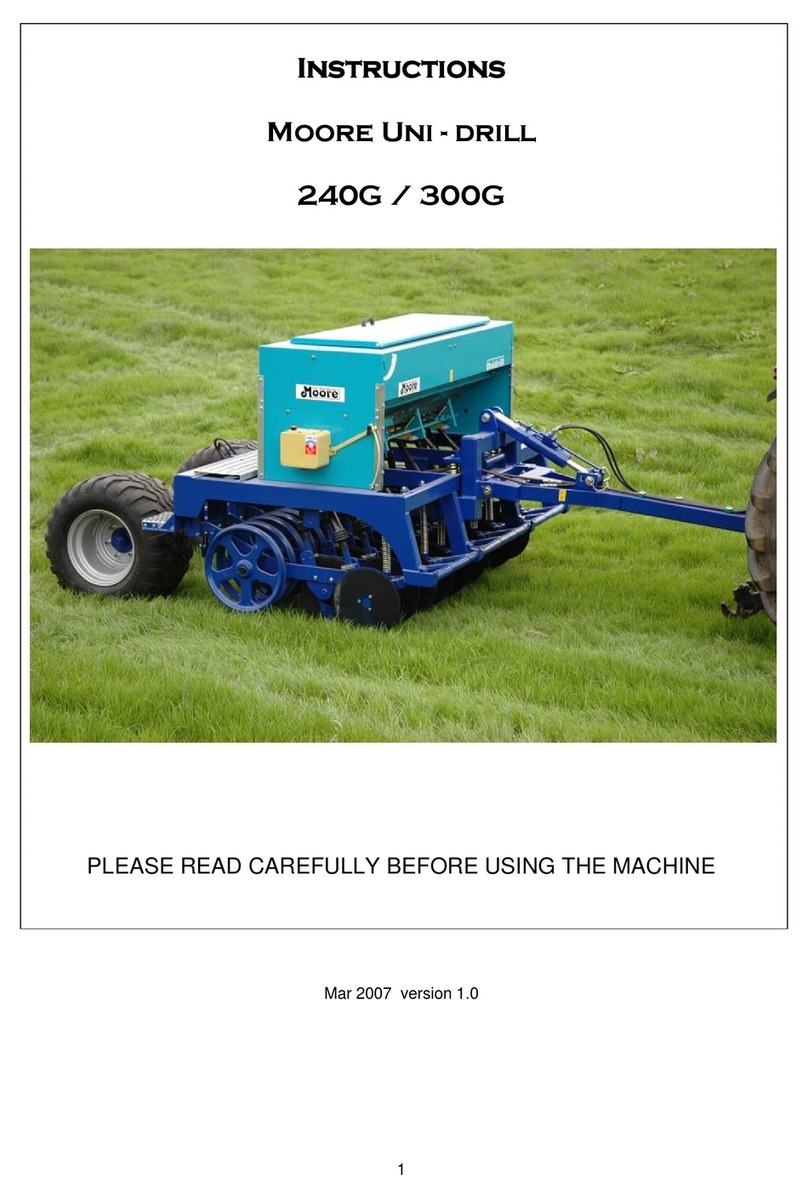
Moore 300G User manual

Foreword
Please read and observe these instructions very carefully before you proceed to operate the seed
drill. This way you will avoid accidents, reduce repair costs and downtime and increase the
reliability and service life of your seed drill. Pay particular attention to the safety instructions!
Moore Unidrill Ltd cannot assume any liability for damage or malfunctions caused by a failure to
observe the instructions contained in this operating manual.
The purpose of this operating manual is to enable you to familiarize yourself with the working
of your seed drill and to make full use of the many possibilities of application which it affords.
The manual will first of all explain the seed drill in general and then proceed to describe the
special features of the different models. The chapters entitled "Additional Accessories", "Care
and Maintenance" and 'Troubleshooting" apply to all seed drill models.
The terms "right", 'left", "front" and "back" are used here for when sitting in the tractor seat
looking forward. This operating manual must be read and used by all persons who are required
to carry out work either on or with the seed drill, e.g.,
•Operation
•Maintenance
•Transporting.
Enclosed with this operating manual is a registration card. Once you have familiarised yourself
with the drill’s operation, please return the registration card to Moore Unidrill Ltd. This will confirm
your acquisition of the seed drill. The period of guarantee commences on the date of delivery.
Moore Unidrill Ltd reserve the right to make changes to the illustrations and data on specifications
and weights contained in this operating manual if we make any improvements to the seed drills.
Seed drill identification.
Once you have accepted delivery of the seed drill, please enter the following data:
Serial No: ....................................................................................
Seed drill model: .........................................................................
Working width: ............................................................................
Number of coulters: ....................................................................
P.T.O. shaft speed: ....................................................................
Accessories: ....................................................................................
Date of issue of Operating Manual: April 2021
Randalls Farm,
Scottlethorpe Road,
Edenham, Bourne,
Lincs. PE10 0LN
Tel. +44(0)28 2766 44444
reception@moore-unidrill.com
www.moore-unidrill.com

Guarantee Guidelines
1. Our products are guaranteed [or a period of 12 months commencing on the date of deliv-
ery to the user. The guarantee does not cover the replacement of parts subject to wear.
2. Guarantee claims must be submitted on special Moore Unidrill Ltd claim forms to Moore
Unidrill Ltd product support, at PE10 0LN, Bourne. Claims cannot be considered unless
the claim form has been completed in full and submitted no later than 3 months after oc-
currence of the damage or defect giving rise to the guarantee claim.
3. Parts replaced under the terms of the guarantee will first of all be charged to the cus-
tomer pending a decision by Moore Unidrill ltd Product support Department as to
whether or not the guarantee claim is justified Parts replaced under the guarantee must
therefore be returned to our works for inspection.
4. Once the guarantee claim has been acknowledged, a credit note will be issued on the
basis of prices ruling on the date on which the guarantee claim was received and in ac-
cordance with Moore Unidrill Ltd. general terms of delivery and payment.
Safety
Proper Use
Operational safety
No liability for consequential damage
Road safety
Accident prevention
Coupling the seed drill to the tractor
Using the PTO shaft
Using the hydraulic system
Operating the seed drill
Care and maintenance
Please read all safety instructions contained in this operating manual with the utmost care and also
observe all warning signs attached to the seed drill. These warning signs must be kept in a legible
condition and must be replaced if missing or damaged. This is especially the case when whole
sections are replaced when making repairs. Warning signs are available from your dealer or
importer.
Follow these instructions to prevent accidents. These instructions must also be made available
to all other users. You are advised to refrain from any working methods which may be
hazardous.

Proper use
MOORE seed drills are based on state-of-the-art technology and are manufactured in
accordance with recognized safety requirements. Nevertheless, the use of these seed drills does
not preclude the risk of injury to the user or third parties and/or the risk of damage to the seed drill
itself or to other materials or items of equipment.
Always make sure that the seed drill is in a technically perfect condition and that it is used
properly and for its intended purpose and entirely in accordance with the instructions given in this
manual! Any malfunctions or defects which might affect the safe operation of the seed drill must
be immediately eliminated.
The seed drill may be used, maintained and repaired only by persons who are familiar with
its working and have been made fully conversant with the risks involved.
OEM replacement parts and accessories from Moore Unidrill have been specially designed for
use with Moore Unidrill drills. Any replacement parts and accessories not supplied by Moore
Unidrill have not been tested or approved by us. The installation and/or the use of non-Moore
products may under certain circumstances have a negative influence on the given design features
of your seed drill and may therefore adversely affect its safe and reliable operation and your
safety.
Moore Unidrill cannot be held liable for damage or injury caused by the use of non-
OEM replacement parts or accessories.
Moore Unidrill seed drills are intended for seeding (sowing). Any uses other than those for which
the seed drills are intended, such as transportation, will automatically exempt or the supplier
from its/their Moore Unidrill liability in respect of ensuing damage. Such cases of improper use
will therefore be entirely at the user's own risk.
All relevant accident prevention regulations, as well as other generally acknowledged safety
and health regulations and road traffic regulations, must be strictly observed.
Improper use also comprises failure to observe the instructions given in this operating manual
and the manufacturer's maintenance and servicing requirements.
Operational safety
The seed drill must not be put into operation until the user has been given proper initial instruction
either by the dealer or by one of Moore Unidrill Ltd representatives or employees. Completed
registration cards are to be sent to Moore Unidrill Ltd
The seed drill may be used only if all safety devices, e.g. detachable guards, are fitted and in
proper working order.
Nuts and bolts should be checked at regular intervals and tightened if
necessary.
Tyre pressures must also be checked regularly.
In the event of a malfunction, immediately cease operation and secure the seed drill in its
stationary position. Malfunctions must be eliminated immediately.

No liability for consequential damage
Even though your Moore Unidrill seed drill has been manufactured with the utmost care and
you are using it properly, fluctuations and interruptions in seed delivery may still occur, the
possible causes being:
•differences in composition of the seed or fertilizer (grain size, density, shape,
dressing, treatment)
•clogging or bridging (e.g. through foreign bodies, glumaceous seed, sticky dressing
agents, moist fertilizers)
•worn parts (e.g. metering device, V-belt)
•damage through external influences
•incorrect drive speeds and forward speeds
•incorrect setting of seed drill (wrongly mounted, failure to observe calibration charts)
•incorrect connection or operation of the electronic seed drill drive or an error in the
tractor's electric installation.
It is therefore advisable, both before and during use, to check that the seed drill is functioning
properly and delivering the seed with the required accuracy. Such deviations in the delivery rate
are only partially detectable by the electronic seed drill control and the monitor of the electronic
seed drill drive!
Any claims for damages not directly incurred by the seed drill cannot be accepted. By the same
token, Moore Unidrill cannot be held liable for any consequential damage resulting from incorrect
metering or distribution.
Road safety
Road traffic regulations must be observed when towing the seed drill on roads, paths and
other public places. The seed drill must be in a roadworthy condition!
Observe the maximum permissible width for road transport and fit all necessary rear
lights, warning signs and guards. Disconnect the electrical supply when fitting.
Fold up the side sections, track markers, etc. and secure them in the transport position. When
transporting the seed drill on the road, lock the control valve in the tractor cabin in order to
prevent the coulter bar from being opened out accidentally. In addition, close the ball valve in the
hydraulic hose.
Trip ropes for quick-release couplings must hang loose and must not, when in their
lowered position, release the couplings of their own accord.
Observe maximum permissible axle loads, the load-bearing capacity of the tyres and the
maximum total weights in order to ensure adequate steering and braking. The behaviour of the
tractor is also influenced by attached implements. Take the width and balancing weight of the seed
drill into consideration, especially on sharp bends.
No persons may be allowed to ride on or in the seed drill.

Accident prevention
Care must be paid not only to the safety instructions contained in this operating manual but also to
'the accident prevention regulations governing the operation of agricultural machinery.
Coupling the seed drill to the tractor
The work of coupling and uncoupling the seed drill (using the three-point linkage) involves a
high risk of injury. The following instructions must therefore be carefully observed:
•Secure the tractor in such a way that it cannot roll forwards or backwards.
•Slowly and carefully work the three-point power lift system.
•Be extremely careful when working with a three-point linkage.
•Position the seed drill with its support legs on firm, level ground.
The tractor and the seed drill must be equipped with the same category of three-point linkage.
Using the PTO shaft
See operating instructions for universal joint shaft!
Use only the universal joint shaft which is intended for use with your seed drill and make sure that
it is fitted with the prescribed protective equipment (protective tube and funnel-shaped P.T.O. shaft
guard must be fitted). Make sure that the tractor engine and the P.T.O. shaft are switched off
before proceeding to fit the universal joint shaft.
Make sure that the tubes overlap by the prescribed distance in both transport and
operating position and are secured in such away that they cannot rotate with the shaft.
Be absolutely sure that there is nobody standing in dangerous proximity to the seed drill when
you switch on the P.T.O. shaft.
The P.T.O. shaft speed of the tractor must correspond with the maximum permissible
rotational speed of the seed drill. The angle of attachment will depend on the type of P.T.O.
shaft (see operating instructions for P.T.O. shaft).
Always switch off the P.T.O. shaft whenever the P.T.O. shaft is not required.
Using the hydraulic system
Do not connect the hydraulic hoses to the tractor's hydraulic system until you have made sure
that the system is at zero pressure on both the tractor and the equipment side.
The hydraulic system generates extremely high pressures. All piping, hoses and connections
must therefore be checked regularly for leakage and visible external damage! Use a proper and
thorough means of searching for leakage and repair all damage immediately! Spurting hydraulic
oil can cause injuries and fires. Call a doctor immediately in the event of injury!
In order to exclude the possibility of incorrect connection, all mating plugs and sockets belonging
to the hydraulic connections between the tractor and the seed drill should be marked with

matching colours. Ensure hydraulic fittings are clean and free of grit / mud that could cause
damage.
Operating the seed drill
Prior to start-up and operation, make sure that nobody is standing in dangerous proximity to
the seed drill.
No persons may ride on the seed drill during operation.
None of the prescribed guards supplied with the seed drill may be removed during operation.
Care and maintenance
Observe all maintenance check interval guidelines and inspections.
Before carrying out any care or maintenance work, always de-pressurize the hydraulic system
and switch off the P.T.O shaft and the tractor engine. Uncouple the seed drill from the tractor.
Make sure, prior to carrying out any care or maintenance work on the drill, that the seed drill is
standing on firm, level ground and cannot roll away or tip over (support legs). Use the steps
provided for access to the drill, do not use parts of the frame.
When cleaning down the drill, ensure any electrics are covered to avoid water damage.
All hydraulic lines must be checked for leakage, looseness, abrasion and damage. All defects
and damage must be immediately rectified.
Prior to carrying out maintenance and repair work on the electrical system, disconnect it from
the power supply.
When carrying out any welding on the seed drill, disconnect the drill fully from the tractor.
All screw connections which had been slackened or unscrewed for maintenance and repair
purposes must now be refitted and properly tightened.

Description and technical detail.
1. Hopper Access Steps
2. Hand Rail
3. 850L Hopper
4. Tractor Top Link
5. Cat 3 Linkage Mount
6. 1000rpm PTO Drive Fan (*Option Hydraulic)
7. Parking Stand in work position
8. Rear Packer Depth Rams
9. Land Drive Wheel
10. Hopper A-Frame
11. Rubber Suspension Arms
12. Seeding Coulter Disc Assembly
13. LED Road Lights
14. Guttler Greenmaster Self-Cleaning Packer Roller
1
2
3
4
5
7
8
9
10
12
14
6
11
13

Setting and using the seed drill
Road transport
Fit warning signs and the necessary lighting and guards for road transport.
Make sure the seed hopper is empty before you proceed to transport your seed drill along
the road.
The maximum speed at which the seed drill may be transported on the road is 25km/h
Retract the Seeding drive wheel and lock it in position.
Fold up the hopper access steps.
Prior to sowing
Coupling the drill to tractor
When coupling the seed drill to tractor, make sure there are no persons standing between
the tractor and the seed drill.
Set the tractors draft links in such a way that the seed
drill can swing sideways only very slightly, and so that
each arm can float independently, and allow the rear
packer to control the seeding depth independently of
the tractor. After hitching on to the lower links, raise the
drill and fold up the parking stands, slide them inside
the chassis and secure with the linch pins provided.
Swingometer Lower the lower link arms and then attach the top link.
The top link should be positioned as high as possible
on the tractor and as low as possible on the
headstock so that the seed drill is as parallel as
possible with the ground when raised.
On level ground, Set the top link length so that the swingometer on the side of the drill points to
the middle position, to indicate that the chassis is level, so that both front and rear discs will
operate at the same depth.
Make sure the tractor engine and PTO are switched off before you proceed to fit the universal
joint shaft.
Observe the special operating instructions for the universal joint shaft. (If Fitted)
In the case of some tractor models, the universal joint shaft must be cut to the correct length. This must
be done in such a way that the power transmission is not adversely affected. After shortening

the shaft, cut the PTO drive shaft guard to size at both ends and then de-burr, clean and grease
the protective tubes and the special section tubes.
After it has been adapted fit the universal joint shaft.
The PTO shaft speed of the tractor must correspond with the maximum permissible rotational
speed of the seed drill.
In the field pull out the land drive wheel and secure with pins provided in working position. An
adjustable stop can be used to set the downward limit of the drive wheel.
When unhitching the drill, fully extend the hydraulic packer rams so the machine is in its
shallowest working position and the packer is carrying the weight of the drill. Set the drill down,
and uncouple the top link first, then raise the drill, with the full weight on the rear packer, and at
this point, and at this point pull out the parking stands, so that the hinge is just proud of the
chassis, unfold them, and gently lower the drill onto the stands, making sure the hinge mechanism
has engaged properly on both sides until they have taken the remaining weight, at which point,
uncouple the lower link arms.
FAILURE TO FOLLOW THIS PROCEDURE WILL CAUSE DAMAGE TO THE HINGE
MECHANISM ON THE PARKING STANDS.
Setting the sowing depth
The sowing depth can be adapted to the soil conditions by adjusting the coulter pressure.
This is done by adjusting the hydraulic packer depth control ram to the desired depth on the
sliding depth sight gauge. The rear packer acts as a depth stop and can increase and decrease
the amount of pressure on the discs.
(If Fitted) In normal circumstances, in good moist conditions, very few of the removable ballast
weights are required to achieve grass and small seeding depths, and so these 27kg weights, can
be added and removed as required. Please observe HSE manual handling guidelines.
When the desired seeding depth is achieved, check that the front and rear coulters are sowing at
the same depth, by re-adjusting the top link again, and keeping the swingometer in the central
and therefore level position.

Calibration and sowing operation.
Setting the Seed Rate
To obtain the desired seed rate, please refer to the seed rate calibration chart,which
indicates the settings for medium to large seeds on the left-hand side and fine seeds on the
right-hand side.
SEED RATE CHART
Type of
seed:
Wheat
Rye
Barley
Oats
Beans
Peas
Lupines
Vetches
Corn
Grass
Type of
seed:
Rape
Red clover
Grass
kg/dm3
0,77
0,74
0,68
0,5
0,85
0,81
0,76
0,83
0,79
0,36
kg/dm3
0,65
0,77
0,39
Standard seeds Kg/ha Fan opened –N-
Fine seeds Kg/ha Fan ½ closed-F-
Standard seeds
10
34
33
32
24
23
21
28
32
8
Fine seeds
2,50
1,80
0,90
2,30
1,15
15
51
49
48
35
42
40
45
51
24
18
5,00
4,60
2,30
5,30
2,65
20
69
66
64
47
61
59
62
70
47
26
7,50
6,80
3,40
8,60
4,30
2,80
1,40
25
86
83
79
59
79
78
79
89
70
34
10,0
0
9,10
4,55
12,0
0
6,00
5,20
2,60
30
104
100
95
71
98
97
96
108
92
42
12,5
0
11,4
0
5,70
15,3
0
7,65
7,20
3,60
35
122
117
111
82
116
117
113
127
115
50
15,0
0
13,7
0
6,85
18,0
0
9,00
9,20
4,60
40
140
134
127
94
135
136
130
146
137
17,5
0
15,9
0
7,95
21,3
0
10,6
5
11,2
0
5,60
45
157
151
143
106
154
155
147
165
156
20,0
0
18,2
0
9,10
24,0
0
12,0
0
13,2
0
6,60
50
174
168
159
118
172
174
164
184
175
22,5
0
20,5
0
10,2
5
26,6
0
13,3
0
15,0
0
7,50
55
192
184
174
130
191
194
181
203
194
25,0
0
22,8
0
11,4
0
27,5
0
13,7
5
16,2
0
8,10
60
210
200
190
141
209
213
198
222
212
N
M
N
M
N
M
65
228
217
206
153
228
232
216
241
231
70
246
235
222
165
246
251
234
260
249
75
264
252
238
177
265
270
251
279
267
80
281
269
253
189
283
289
268
298
285
85
298
286
268
200
302
309
285
317
304
90
316
302
284
212
320
328
302
336
323
95
335
319
300
224
338
347
320
355
342
100
352
337
316
236
356
366
337
374
361
N - NORMAL -M - MICRO
105
370
354
332
248
374
385
354
393
380
85 handle turnings = 1/10 ha
110
387
371
348
260
393
404
371
412
398
Depending on the calibration chart side to be used, the following settings apply:
LEFT HAND SIDE –Standard seeds
Position red knob 3 (pict. 1) to N position - right
Set RED gear to position N (pict 2)
Set fan airflowvalve to fully opened N (Pict 3)
RIGHT HAND SIDE –Fine seeds
Withhandle 4 move the indicator to 0 on the scale
Position red knob 3 (pict. 1) to F position –left
Set RED gear to position N (pict 2) for
readingcolumn N (NORMAL) or
Set RED gear to position M (pict 2) for
readingcolumn M (MICRO)
Set fan airflowvalve to half opened F (NOT APPLICABLE FOR OILSEED RAPE)
Pict 1

NOTE: Make all the above operations only when the hopper is empty or by rotat-
ing the metering system to avoid damages to the unit.
By rotating the handle 4, set the reading on the scale to the same number shown in the
chart depending on the seed type and rate required. The adjustment range for position N
of red knob3 is 0-110 whereas for position F of red knob 3 is 0-25. DO NOT force the
screw after 25 when in position F to avoid breakages.
NOTE; When an adjustment to a lower figure is required, the adjustment must be made
whilerotating the calibration handle.
CALIBRATION TEST
The calibration test is necessary to confirm that the desired seed rate will be achieved
in the field.
Ensure the hopper is at least half filled with seed.
Undo the thumbscrewthat holds the plastic elbow7 andplace a bucket beneath the opening.
Remove the drive shaft to the land wheel attached to shaft 1 (pict 2) and replace it with
the handle.
Turn the handle anticlockwise a sufficient number of times until the seed flows evenly
from themetering device. Empty the bucket into the hopper and put it back under the
metering unit.Check that the correct scale value remains as set.
Turn the handle anticlockwise 85 times at 1 turn per second. The collected seed quan-
tity in the bucket corresponds to the quantity sown on a 1/10 of a hectare. Therefore
the weightmultipliedby 10 gives a rate in Kgs/Ha.
If this quantity differs fromthe one required, repeat the test after adjusting the scale until
the correct weight is achieved -ie; move towards higher numbers if an higher rate is
requiredor vice-versa.
At the end of the test, replace the elbowand the drive shaft.
NOTE: The above figures have been calculated with an average number of land wheel
turningsover 100 mts. of 44 which correspond to the 85 handle turnings requiredfor the
calibration.
Various factors can affect the wheel slip and circumference thus affecting the seed rate.
FINE/Micro Seed Calibration
Whenverylowrates are required, by pullingthe red
gearout, position M pict 2, the speed is halved
therefore to obtain the same rate the width of the
metering vane must be doubled as shown by the
scale in the M columns on the righthandside of the
calibration chart.
This reduces the possibility of errors since the self
cleaning effect of the vane is increased. To further
increase the precision when metering small
seeds, a cleaning brush is fitted inside the unit to
keep cleaned the small seeds vanes.
PICT 3

Whendrilling small seeds check that the cleaning brush is ingood workingorder.
CARE AND MAINTENANCE
DAILY MAINTENANCE
Clean the brush for the fine seed barrel regularly to avoid blockages.
Grease the PTO shaft yokes andguards daily throughthe appropriate nipples.
Grease all the pivot points provided with grease nipples.
Check the fan belt for tightness and adjust it if necessary.
Check allnuts and bolts for tightness before starting work and during the first 40 hours.
Check allwearing parts for tightness and breakage and replace them if necessary.
Check all electricalconnectors
EMPTYING THE HOPPER AND METERING SYSTEM
After drilling, the hopper and metering system must
beemptied completely.
To empty the hopper, place a suitable container un-
der thehopper and open the gate valve.
To empty the metering system, open the rear door, insert
and turn the calibration handle to clear all the vanes and
remove any seed, remove the elbow and cleanit fromany
seed.
It is important to clean the machine thoroughly
to avoid rodent damage.
DAMPNESS
If water enter inside the hopper and tubes, it is important to run the fan until the tubes
are dry to avoid seeds and dressing mixing with the moisture and creating blockages.
STORAGE AND POST SEASON
Before storing the machine, check all the parts for wear and damages and replace themas
necessary.
When parking the machine, ALWAYS, use the parking legs fitted to the coulter bar to
relievethe weight fromthe coulters
Protect allthe electricalconnectors with water repellent products.
Hydraulic Drive Fan Drills (*Optional)
Safety precautions
Moore Unidrill does not accept liability for damage due to incorrect usage of the drill to either the
drill or tractor. Only trained and competent persons should carry out repair and changes to the
Hydraulic Fan. At all times, disconnect the hydraulics before working on the machine.

Product data
Chart 2 Product data of hydraulic drive of the fan
Working
Oil Flow
Type
Hydraulic motor
Fan
Width
(Rate)
Displacement
Speed
(l/min)
Fan Speed
(cm3)
(rpm)
(rpm)
MK
3m
8
4200
40
4200
Installation of hydraulic hoses
Oil escaping under high pressure can penetrate clothing and skin and causes serious injuries. In case
of injury, emergency first aid services should be called.
Always fit the hydraulic hoses so that they won’t be damaged or exposed to chafing while lifting the
seed drill up and down in work.
Connecting to the tractor
The Oil flow is directed to the 3-way flow control valve and is thus regulated according to the speed
of the hydraulic motor. The constant oil flow rate give the speed ofthe hydraulic fan drive. This speed
is controlled via the display on the terminal or by using a speed sensor.
Freeflow return
The freeflow return prevents damage to the hydraulic motor.
!
Maximum permissible pressure in the freeflow return is 10 bar.
The hydraulic motor will be damaged by overpressure.
Following points must be taken into account when selecting the position of the back branch
connection to the tractor hydraulic system:
Return oil must flow through the tractor hydraulic filter system.
Return oil must not flow through any regulation valves (freeflow return) to avoid any
backpressure.
Operation
!
Maximum permissible fan revolutions is 4200 rpm. Only adjust the revolution speed
while the fan is switched off.
A= Input to the hydraulic valve/motor
B= Outlet from the hydraulic valve/motor
P= Input (From the tractor)
T= Outlet (return at less than 10 Bar back pressure)
Three-way regulation valve

Connection to the tractor
Hyd. fittings and connectors can differ depending on tractor manufacturer.
Perform the connections on the tractor in following order:
1. Outlet (T)
2. Input (P)
First putting in operation
With first putting in operation, the revolutions have to be adjusted until the hydraulic oil reaches the
operational temperature and the fan revolutions are stable.
In case of operating with cold oil the fans speed is higher until the oil has reached operational
temperature.
Application on various tractors
On tractors with the flow regulating valve
Open the flow-regulating valve fully. (The 3-way flow control valve is fully open when the adj
screw is fully screwed in)
Activate the operating valve on the tractor.
Set the desired fan speed by regulating the oil flow rate on the tractor
On tractors without the flow regulating valve, without the regulating pump
Set the desired speed with
the adjusting screw at the 3-way flow control valve
On tractors without the flow regulating valve, with the regulating pump
The three-way flow regulating valve must be switched from 3-way to 2-way. The adjustment has
to be done as follows:
Release the safety nut
Thread in the screw completely. The conversion to a 2-way flow control is now complete.
Re-tighten the safety nut.
Set the desired speed with the adjusting screw on the2-way flow control valve.
!
The switch from the three-way to two-way flow regulating valve, or in the opposite direction,
must be done when the fan is off. Adjusting while the fan is running will cause damage to the
machine.
Care and Maintenance
All maintenance should be carried out with machine unhitched, with packer roller on lowest pin
position, the top link unattached, and both front stands in park position. There is no need ever to
get underneath the machine whilst mounted on the tractor. All maintenance and checks can be
achieved whilst in the park position. In the highly unlikely event of coulter blockage, this can be
relieved, by undoing the corbin clips which attach the flexible seed pipes on top of the tungsten

seed tube coulters, and relieving the blockage with a long screw driver or piece of stiff wire from
above. When removing arti
cles for service, please observe HSE manual handling guidelines. Common service component
weights are listed in the full spare parts list included later in this operating manual.
Guttler roller
The Guttler roller is self cleaning except at each end, were the hardox scrapers work to clean the
back to back 50cm rolls. Scrapers should be adjusted and replaced as necessary.
Guttler roll main bearings (1 on each end, and 2 in the middle) should be greased every 20 hours
of work and before storage.
Nuts and bolts
All nuts and bolts should be checked regularly. When working in stoney or trashy conditions it will be
necessary to check all nuts and bolts daily, particularly the seed tube coulters and disc bolts.
Seed tube coulter adjustment
Check the position of the seed tube coulters in relation to the disc coulters daily.
For most seeding conditions and as a general rule the tip F of the seed tube coulter should be
set so that it is approximately 12mm above the outer edge of the disc.
The leading edge of the seed coulter should be set parallel
to the disc and just touching it. This can be achieved by
means of the retaining bolts A and B and the adjusting
screws C and D. If the tip, F, of the seed coulter is out from
the disc, this can be corrected by tightening bolt A (front
bolt) more than bolt B, while the top, G of the seed coulter
can be brought in towards the disc by tightening Bolt B
(rear bolt) more than Bolt A. Some discs, may be slightly
distorted, but when in work the side force of the soil on the
disc will keep it in contact with the seed coulter. A certain
amount of bedding in and wear takes place between the
disc and the seed coulter and it may become necessary to
adjust screws C and D to position the seed coulter close to
the disc
3

MOORE UNIDRILL 300G August 2016 S/N 8314-
Guttler roller
3
1.
PA900597
UCF 40mm bearing
4
2.
PA900354
45cm special end Guttler
3.
PA900420
Guttler scraper holder
5
4.
PA900595
Guttler hardox scraper
2
5.
PA900464
50cm Guttler
66.
PA900331
45cm Guttler
1
7.
PA900892
1472mm shaft to fit 40mm
7
3
4
5
1.
PA900775
RH grass suspension
2.
PA900776
LH grass suspension
1.
PA900777
RH arable suspension
2.
PA900778
LH arable suspension
1.
PA900779
RH arable outer unit
2.
PA900780
LH arable outer unit
3. PA900021
rubber sausage 300
4.
PA900002
m12 nyloc
5.
PA900028
m12 x 40 cup head 8.8
6.
PA900616
suspension arm upper
7.
PA900026
m10 x 70 bolt
8.
PA900013
seed tube retaining plate
9.
PA900089
m10 x 20 set screw
10. PA900152
right hand coulter t’sten
11. PA900153
left hand coulter t’sten
12. PA90029
Hub Bearing
13. PA900007
3/8”M10 split washer
14. PA900010
3/8”x 3/4” set screw
15. PA301515
M16 Binx nut
16. PA900008
410 x 5 serrated disc

MOORE UNIDRILL 300G August 2016 S/N 8314-
Parts list of common serviceable components.
Part No
Material
Quantity
PA900029
Moore Unidrill Peer Hub 5 hole 3/8" UNF
1
PA900775
RH Grass Suspension Unit
1
PA900776
LH Grass Suspension Unit
1
PA900777
RH Arable Suspension Unit
1
PA900778
LH Arable Suspension Unit
1
PA900779
RH Arable Outer Suspension Unit
1
PA900780
LH Arable Outer Suspension Unit
1
PA900616
Upper Suspension Arm Bracket
1
PA900008
Moore Unidrill Notched 415x5mm Disc 5 Hole
1
PA900152
Right Hand Tungsten 30mm Coulter
1
PA900153
Left Hand Tungsten 30mm Coulter
1
PA900010
3/8 X 3/4"UNF SET SCREW
5
PA900007
3/8 Rectangular Spring BZP Washer
5
PA900013
Seedtube Retainer Plate
1
PA900035
Rubber Cord Suspensions 240mm (32 Row)
4
PA900021
Rubber Cord Suspensions 300mm (24 Row)
4
PA900028
M12 x 40 Cup Square Bolt 8.8
8
PA900465
Cat 3 Top Link Pin
1
PA900422
Cat 3 Bottom Link Pin
2
PA900274
Cat 2 Pin 25.4x110
2
PA900421
Parking Legs LH/RH (Pair)
2
PA900052
7/16 Lynch Pin
15
PA900626
LED Lights
2
PA900349
7 Pin Plug
1
PA900423
Light Mounting Brackets LH/RH (Pair)
2
PA900420
Guttler Scraper Mounting Plate
2

Part No
Material
Quantity
PA900595
Guttler Hardox Scraper
2
PA900457
Drive Wheel Rest
1
PA900597
Guttler Packer Bearing
4
PA900354
Guttler 45cm End Ring
4
PA900464
Guttler 50cm Ring
26
PA900331
Guttler 45cm Ring
22
PA900892
1472mm Packer Shaft
2
PA900509
1.25" Washer Pin & Split Pin
2
PA900652
1/4" Lynch Pin T1
2
PA900466
Handrail
1
PA900467
Step Frame
1
PA900400
Safedeck 360x750
1
PA900399
Safedeck 300x750
1
PA900449
Hectametre
1
PA900017
A2 6B Corbin Clip
64
PA900054
Hose Holder Plastic Sleeve
32
PA900433
Walterscheid PTO Shaft
1
PA900655
PTO Yoke 30mm Round
1
PA900415
SPZ1512 Drive Belt
2
PA302914
Replacement Landwheel for 3m
1
PA900639
27kg Wafer weights
20
PA900215
Amber Reflector Amber Round Sticky
2
PA900654
Top Link Cat 2 7"
1
PA900628
LED 2 Chamber Rear Lamp c/w 7m
2
PA900312
Red/White Triangle Reflector
2
PA900273
50x30 D/A Cyl 420x134 Stroke Ram
2
PA900863
7 Pin Stocket Mounting Bracket
1
PA900649
3/8 D/A Check Valve
1

MOORE UNIDRILL 300G August 2016 S/N 8314-
Techniques
The Moore Unidrill prepares its own mini seedbed by using an angled disc and seed tube coulter
tine. All seeds are planted at a constant depth, The points of the Guttler roller slit the ground 305
times per square meter, to give good seed soil contact, however in some conditions another
pass with a flat roll is necessary. In all conditions, drilling should be conducted in reasonably
straight lines as turning with the drill engaged in the ground, can cause premature bearing
failure, and blockages, by pulling disc away from seed tube coulters.
Direct drilling grass or clover into grass
A healthy field of grass is one of the most valuable assets a livestock farmer can have and direct
drilling can help you grow more and better grass at less cost, because there is less labour,
machinery and time involved. Other benefits are reduced poaching, a reduction in the number of
broad-leaved weeds, and the direct drills ability to tackle even quite “difficult” land. The direct
drilling of grass into either a short term or midterm sward is a simple enough matter, and even
older worn-out pastures can be reseeded with the direct drill provided a few precautions are
observed.
A one-to-ten-year-old sward which is open, presents few problems having had no time to build up
any substantial quantity of mat/thatch under the surface. As a rule of thumb, if you can sink the
disc into 25mm of 80% clean soil and not root mat and thatch, then you are in business. As with
all reseeding, weather plays an important part, but with reasonable moisture and heat the
following methods may apply for successful seeding.
Method 1, No chemical top up.......clean (weed free) open swards following silage.
Where a final cut of silage is being taken, and the field is going to grazing, cut low to the ground
and direct drill 1/2 to full rate seeds as soon as possible, whilst moisture is retained in the ground,
and before the regrowth starts. There should be enough moisture retained in the ground to get the
seeds germinated and provided it doesn't dry out subsequently due to lack of rain, seed should be
established before the old sward has fully recovered and should be grazed with young stock or
sheep 2 to 4 weeks later, depending on growing conditions. This grazing keeps the old grass
down, stops the old sward choking the new seedlings, and allows light into the newly established
grass. This sward should be grazed in 2/3 weekly intervals until the end of the season, never
overgrazing as this can cause the new seedlings to be pulled out. Newly established grass often
does not normally become apparent until the regrowth following first cut the following season.
Check the Ph of ground prior to seeding and apply lime as necessary to get the ideal pH of
6.5, especially with clover. A light to medium coat of slurry immediately after seeding
(depending on moisture) can be applied providing it contains no effluent or dairy washings.
Method 2, No chemical top up.......clean (weed free) open swards following grazing.
Graze the sward really bare, using a mob stocking rate, harrow/rake/roll the dung pats if
necessary, drill the sward, and keep the stock grazing on, until the new shoots are just visible. As
above re graze in 2 to 4 weeks’ time, depending on growth.
Check the Ph of ground prior to seeding and apply lime as necessary to get the ideal pH of
6.5, especially with clover.
A light to medium coat of slurry immediately after seeding (depending on moisture) can be
applied providing it contains no effluent or dairy washings
Table of contents
Other Moore Farm Equipment manuals
Popular Farm Equipment manuals by other brands

Kersten
Kersten KM 10037 H-FKDR Original operating instructions

AKO-Agrartechnik
AKO-Agrartechnik BA-1165 instruction manual

First Products
First Products UA60T Operator's manual & parts list

AXT ELECTRONIC
AXT ELECTRONIC VSE Insruction manual

Spearhead
Spearhead Multicut 620 Handbook

Krone
Krone Fortima F 1250 Original operating instructions

horsch
horsch Maestro 12 SV Translation of the original operating instructions

Raven
Raven AIM Command FLEX installation manual

FarmTek
FarmTek Growers Supply HydroCycle Vertical Aeroponic... Important information

Fast
Fast 8200 Operation manual

Wacker Neuson
Wacker Neuson GreenTec 1402 Handbook

GSI Group
GSI Group TopDry 2000 Series installation manual