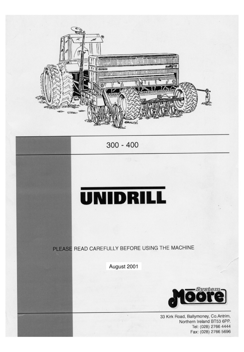
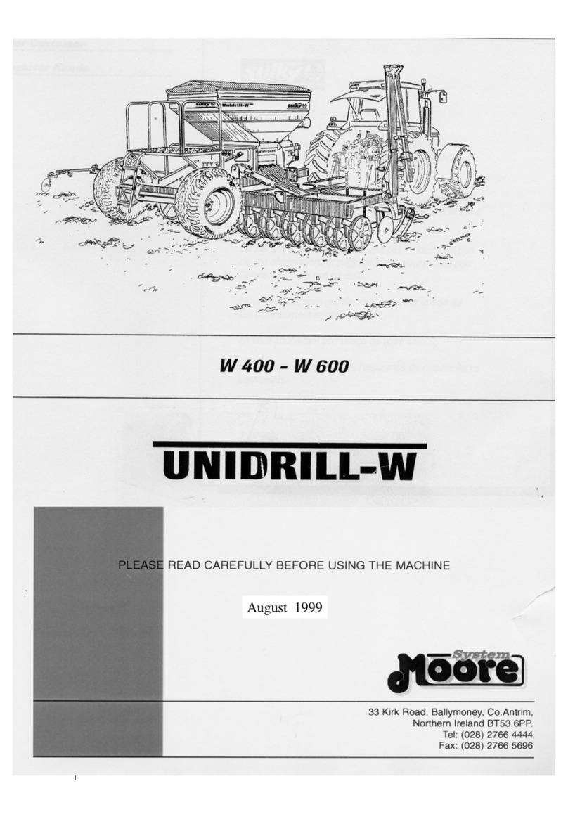
Moore Tandem Uni-Drill DP400A User manual

Instructions
Tandem Uni - drill
DP400A / DP600A
PLEASE READ CAREFULLY BEFORE USING THE MACHINE
June 2005 stdpa version 2.0
1

Dear Customer
Thank you for trusting our equipment and choosing the
Tandem UNIDRILL.
To ENSURE correct operation, and make full use of
your seed drill’s capabilities, we recommend that you
read this operators manual carefully.
Please do not hesitate to make suggestions or
comments based on your experience; they will
always be of use to us, and will help us improve our
products.
Please return the duly completed guarantee form to us.
We wish you success with your seed drill.
Yours sincerely
Sam Moore
Managing Director
2

Guarantee Form
Moore Uni Drill Limited
33 Kirk Road , Ballymoney,
Co. Antrim , N. Ireland, BT53 6PP
Tel : +44(0)28276 64444
Fax +44(0)28276 65696
Machine Width:
3
Serial Number:
Customer Name:
Address:
Tel:
Mobile No:
E. mail : Post Code :
I HAVE RECEIVED THE ABOVE MACHINE IN AN ACCEPTIBLE CONDITION AND TO
THE CORRECT SPECIFICATION.
I HAVE RECEIVED AND READ THE OWNERS MANUAL FOR SAFE AND
CORRECT OPERATION OF MACHINE.
I WISH TO REGISTER MY MACHINE FOR WARRANTY
SIGNED :- CUSTOMER DATE : -
1. To be completed, detached and returned to Moore Uni Drill within 14 days
of customer receipt / purchase.
2. It is essential that all details be completed.
3. Failure to complete and return this form will prevent claim settlement

Declaration of Conformity
Moore Uni Drill Limited,
Of 33 Kirk Road, Ballymoney, Co. Antrim, N. Ireland. BT53 6PP
hereby declare that
Model ………………………………
Serial No …………………………..
Date ………………………………..
conforms with the following Directives and Regulations, and has been
certified accordingly.
The Essential Health and Safety Regulations Directive. 98 – 37 - EC
The Proposed Seed Drills Safety Document 2000
(00/714171 DC)
Certified on behalf of Moore Uni - Drill Limited
James A O’ Kane
Technical Engineer
4

Safety Regulations
•These symbols are used in these instructions every time recommendations are provided concerning
your safety, the safety of others or the correct operation of the machine.
•These recommendations must be given to all users of the machine.
GENERAL SAFETY
REGULATIONS
5
Every time the tractor/machine
assembly is to be started up and
used, you should ensure
beforehand that it complies with
current legislation on safety at
work and Road Traffic
regulations.
___________________________
___
GENERAL
1 - In addition to the instructions
contained in this manual,
legislation relating to safety
instructions and accident
prevention should be complied
with.
2– Warnings affixed to the
machine give indications
regarding safety measures to be
observed and help to avoid
accidents.
3 – When traveling on public
roads, abide by the provisions of
the Highway Code.
4– Before starting work, it is
essential that the user is familiar
with the control and operating
elements of the machine and their
respective functions. When the
machine is running, it may be too
late.
5– The user should avoid
wearing loose clothing, which may
be caught up, in the moving parts.
6– We recommend using a
tractor with a safety cab or roll bar
conforming to standards in force.
7 – Before starting up the
machine and beginning work,
check the immediate
surroundings, particularly for
children. Make sure that visibility
is adequate. Clear any persons
or animals out of the danger zone.
8– It is strictly forbidden to
transport any persons or animals
on board the machine whether it
is in operation or not.
9– The machine should only be
coupled up to the tractor at the
specially provided towing points
and in accordance with applicable
safety standards.
10 – Extreme care must be taken
when coupling or uncoupling the
machine from the tractor.
11 – Before hitching up the
machine, ensure that the front
axle of the tractor is sufficiently
weighted. Ballast weights should
be fitted to the special supports in
accordance with the instructions
of the tractor manufacturer.
12 – Do not exceed the maximum
axle weight or the gross vehicle
weight rating.
13 – Do not exceed the maximum
authorized dimensions for using
public roads.
14 – Before entering a public
road, ensure that the protective
and signaling devices (lights,
reflectors, etc) required by law are
fitted and working properly.
15 – All remote controls (cords,
cables, rods, hoses etc) must be
positioned so that they cannot
accidentally set off any
manoeuvre, which may cause an
accident or damage.
16 – Before entering a public
road, place the machine in the
transport position, in accordance
with the manufacturer’s
instructions.
17 – Never leave the driver’s
position whilst the tractor is
running.
18 – The speed and the method
of operation must always be
adapted to the land, roads and
paths. Avoid sudden changes of
direction under all circumstances.
19 – Precision of the steering,
tractor adhesion, road holding and
effectiveness of the braking
mechanism are influenced by
factors such as the weight and
nature of the machine being
towed, the front axle stage and
the state of the land or path. It is
essential, therefore, that the
appropriate care is taken for each
situation.
20 – Take extra care when
cornering, taking account of the
overhang, length, height and
weight of the machine or trailer
being towed.
21 – Before using the machine,
ensure that all protective devices
are fitted and in good condition.
Damaged protectors should be
replaced immediately.
22 – Before using the machine,
check that nuts and screws are
tight, particularly those for
attaching tools (discs, flickers,
deflectors, etc). Tighten if
necessary.
23 – Do not stand in the operating
area of the machine.
24 – Caution! Be aware of any
crushing and shearing zones on
remote-controlled and particularly
hydraulically controlled parts.

Safety Regulations
6
25 – Before climbing down from
the tractor, or before any
operation on the machine, turn off
the engine; remove the key from
the ignition and wait until all
moving parts have come to a
standstill.
26 – Do not stand between the
tractor and the machine until the
handbrake has been applied
and/or the wheels have been
wedged.
27 – Before any operation on the
machine, ensure that it cannot be
started up accidentally.
28 – Do not use the lifting ring to
lift the machine when it is loaded.
PROPER USE OF THE
MACHINE
The seed drill must only be used
for tasks for which it has been
designed. The manufacturer will
not be liable for any damage
caused by using the machine for
applications other than those
specified by the manufacturer.
Using the machine for purposes
other than those originally
intended will be done so entirely
at the user’s risk. Proper use of
the machine also implies:
- complying with instructions on
use, care and maintenance
provided by the manufacturer;
- using only original or
manufacturer recommended
spare parts, equipment and
accessories.
The seed drill must only be
operated, maintained and
repaired by competent persons,
familiar with the specifications and
methods of operation of the
machine. These persons must
also be informed of the dangers to
which they may be exposed.
The user must strictly abide by
current legislation regarding:
- accident prevention
- safety at work (Health and
Safety Regulations)
- transport on public roads (Road
Traffic Regulations).
Strict compliance with warnings
affixed to the machine is
obligatory.
The owner of the equipment shall
become liable for any damage
resulting from alterations made to
the machine by the user or any
other person, without the prior
written consent of the
manufacturer.
HITCHING
1– When hitching or unhitching
the machine form the tractor,
place the control lever of the
hydraulic lift in such a position
that the lifting mechanism cannot
be activated accidentally.
2 – When hitching the machine to
the three-point-lifting mechanism
of the tractor, ensure that the
diameters of the pins or gudgeons
correspond to the diameter of the
tractor ball joints.
3 – Caution! In the three-point
lifting zone, there may be a
danger of crushing and shearing
4 – Do not stand between the
tractor and the machine whilst
operating the external lift control
lever.
5– When in transport, lifting
mechanism stabilizer bars must
be fitted to the machine to avoid
floating and side movement.
6– When transporting the
machine in the raised position,
lock the lift control lever.
DRIVE EQUIPMENT
(Power take-off and universal
drive shafts)
1– Only use universal drive
shafts supplied with the machine
of recommended by the
manufacturer.
2– Power take-off and universal
drive shaft guards must always be
fitted and in good condition.
3 – Ensure that the tubes of the
universal drive shafts are properly
guarded, both in the working
position and in the transport
position.
4– Before connecting or
disconnecting a universal drive
shaft, disengage the power take-
off, turn off the engine and re-
move the key from the ignition.
5– If the primary universal drive
shaft is fitted with a torque limiter
or a free wheel, these must be
mounted on the machine power
take-off.
6– Always ensure that universal
drive shafts are fitted and locked
correctly.
7– Always ensure that universal
drive shaft guards are
immobilized in rotation using the
specially provided chains.
8– Before engaging power take-
off ensure that the speed selected
and the direction of rotation of the
power take-off, comply with the
manufacturer’s instructions.
9 – Before engaging power take-
off, ensure that no persons or
animals are close to the machine.
10 – Disengage power take-off
when the universal drive shaft
angle limits laid down by the
manufacturer are in danger of
being exceeded.
11 – Caution! When power take-
off has been disengaged, moving
parts may continue to rotate for a
few moments. Do not approach
until they have reached a
complete standstill.
12 – On removal from the
machine, rest the universal drive
shafts on the specially provided
supports.
13 – After disconnecting the
universal drive shafts from the
power take-off, the protective cap
should be fitted to the power take-
off.
14 – Damaged power take-off and
universal drive shaft guards must
be replaced immediately.
HYDRAULIC CIRCUIT
1– Caution! The hydraulic circuit
is pressurized.
2– When fitting hydraulic motors
or cylinders, ensure that the
circuits are connected correctly in
accordance with the
manufacturer’s guidelines.
3– Before fitting a hose to the
tractor’s hydraulic circuit, ensure
that the tractor-side and machine-
side circuits are not pressurized.
4– The user of the machine is
strongly recommended to identify
the hydraulic couplings between
the tractor and the machine in
order to avoid wrong connection.
Caution! There is a danger of
reversing the functions (for
example: raise/lower).
5– Check hydraulic hoses once a
year, for:
- Damage to the outer surface
- Porosity of the outer surface
- Deformation with and without
pressure
- State of the fittings and seals
The maximum working life for
hoses is 6 years. When replacing
them, ensure that only hoses with
the specifications and grade
recommended by the machine
manufacturer are used.

Safety Regulations
6– When a leak is found, all
necessary precautions should be
taken to avoid accidents.
7– Pressurized liquid, particularly
hydraulic circuit oil, may cause
serious injury if it comes into
contact with the skin. In the case
of injury, consult a doctor
immediately. There is a risk of
infection.
8– Before any operation on the
hydraulic circuit, lower the
machine, release the pressure
from the circuit, turn off the engine
and remove the key from the
ignition.
MAINTENANCE
7
1– Before commencing any
maintenance, servicing or repair
work, or before attempting to
locate the source of a breakdown
or fault, it is essential that the
power take-off is disengaged, the
engine turned off and the key
removed from the ignition.
2– Check regularly that nuts and
screws are not loose. Tighten if
necessary.
3– Before carrying out
maintenance work on a raised
machine, prop it up using
appropriate means of support.
4– When replacing a working part
(seed drill coulter or disc etc)
wear protective gloves and only
use appropriate tools.
5– To protect the environment, it
is forbidden to throw away oil,
grease or filters of any kind. Give
them to specialist recycling firms.
6– Before operating on the
electric circuit, disconnect the
power source.
7 – Protective devices likely to be
exposed to wear and tear should
be checked regularly. Replace
them immediately if they are
damaged.
8–Spare parts should comply
with the standards and
specifications laid down by the
manufacturer. Only use Moore
spare parts.
9– Before commencing any
electric welding work on the
tractor or the towed machine,
disconnect the alternator and
battery cables.
10 – Repairs affecting parts under
stress or pressure, (springs,
pressure accumulators, etc)
should be carried out by suitably
qualified engineers with special
tools
Danger
A = Risk of crushing
B = Marker operating zone
C = Moving parts
D = Do not travel on the platform
E = Rotating agitator shaft
D
E
C
A
B

Safety Regulations Safety Stickers
Warning notices relating to safety are affixed to your machine.
Their aim is to contribute to your safety and to the safety of others.
Know their contents and check their location.
Review the safety notices as well as the instructions contained in this operating manual.
If any safety notices become illegible or lost they should be replaced.
8

Safety Regulations Safety Stickers
9

Contents
10
Start Up Pages
A Technical Specifications 11
B Operator Check List 12
C Hitching 13
D Transport 14
E Hydraulic Connections 15
F Hopper Cover 16
G Turbine 17 - 19
Settings
A Distribution 20 - 25
B Sowing Depth 26
C Weight Transfer 27
D Coulter Adjustment 28
E Markers 29
F Half Width Shut Off 30
G Electronic Tramlines 31
H Tramline Track Width 32
Maintenance
A Wear Check 33
B Seed Distribution 34
C Greasing and Lubrication 35
Optional Equipment
A Multiplier 36
B Flexible Agitator 37
C Pre Emergence Marker 38
D Moore Headland Control 38-46
Practical Recommendations 47 – 48
Flow Rate & Calibration Procedure 49 - 55
Warranty 55 - 56

Start Up
11
A : Technical Specifications
When accepting ownership of your machine note the following information:
Serial Number:_____________________
Type of machine__________________________________________________________
Accessories: _________________________________________________________
MOORE UNIDRILL DP400A DP600A
Width (m) 4 6
Number of rows 24 36
Row spacing (cm) 16.6 16.6
Width in transport (m) 3 3
Hopper capacity (l) 1600 2200
Weight (Kg) 3750 5750
Horse Power Required (HP) 130 180

Start Up
12
B : Operator Check list
It is the owner / drill operators responsibility to set up the drill for:
1. Sowing depth according to conditions in each soil type and pre worked condition
2. Tramline bout number to suit tramlines
3. Tramline track width
4. Number of rows shut off whilst tram lining
5. Marker width setting to allow matching of bouts
6. Operation of half width shut off
7. Folding the machine in and out of work without damage
It is also the owner / operator’s responsibility to check the operation of the various
functions of the machine between each hopper fill, or at least once every hour to check the
machine is operating correctly.

Start Up
C : Hitching
If possible use
the pickup
hitch
•To unhitch, set the machine with the transport wheels resting on the
ground
•Beware of the drawbar motion
1 Hitching height
The height of the hitching point greatly influences the performance of the device (+/- 450 mm).
- The hitching point must be fixed.
-Low hitching heights should be preferred,
-The drawbar should be preferred when twin wheels or wide tyres are used, to make field-end
manoeuvering easier.
2 Damper
-This was set in the factory
13

Start Up D : TRANSPORT
1
Users must scrupulously observe traffic regulations on open roads.
Travel only with an empty hopper.
Users must also use the transport pins when making adjustments to the drill
Important: Do not exceed 25 Kilometers per hour TRANSPORT SPEED
TRANSPORT
•Positioning the transport locks (1)
-Raise the seed drill
-Insert the transport locks
-Lower the machine to rest mandatorily on transport locks
Do not stand near the axle during operation
14

Start Up
E : HYDRAULIC CONNECTIONS
Pressure lines will have a RED cap
Return lines will have a BLUE cap
Hydraulic connections
•1 Double-action spool valve to operate valve block
•1 Motor spool valve for hydraulic fan, c/w free flow back to tractor
•1 hydraulic brake connection
When folding the machine in and out of work, park the tractor
and drill on a level surface, lift the drill fully on the front and
rear, insert the transport pins and then fold unfold the drill with
extreme caution.
15

Start Up
F : HOPPER COVER
•Ensure that sieve (1) is in place in the bottom of the hopper bottom.
•Operate with tarpaulin (2) sealed.
16

Start Up G : TURBINE
17

Start Up G : Turbine – Operating Instructions
1) Mechanical
•Use the 1000 RPM power take-off
•Maintain tractor engine rate during work
•Do not engage the PTO on full load
2) Hydraulic
a) Specification
Warning and reminder: a number of checks need to be made on the tractor when using the hydraulic turbine
drive system. Consult your dealer.
1) The minimum oil flow rate required at working RPM is 30 liters/min
2) The oil pressure rises to 180 bars on start-up
3) Feedback must imperatively be below 15 bar; otherwise extensive damage will be caused to
the hydraulic motor. If possible always try to run the oil back into the tractor, without any
restriction, i.e. put the return pipe for the hydraulic fan motor directly into the back of the
tractor without going through the spool valve.
4) When using a tractor with open center hydraulics, use the oil flow regulator on the tractor to control
the speed of the fan and free flow the oil back to tank. If there is no flow regulator on the tractor,
an inline flow regulator will be required for the motor, again free flow back to tank.
5) When using a tractor with closed center hydraulics (John Deere) use a Series 3 SCV valve (motor
Spool). If this is not fitted refer to your John Deere Dealer
6) When using the spool lever to control the hydraulic fan consider the points listed below.
Failure to disengage the fan through the float facility on the spool lever, will ‘dead head’ the hydraulic motor,
this may then destroy the manometer or damage the fan motor seals.
18

Start Up G : TURBINE – Operating Instructions
7) Always clean the hydraulic connection correctly
8) When putting into service for the first time, the number of revolutions must be corrected between
start-up (cold oil) and normal operation (warm oil)
The turbine speed is checked on the Moore Tronic unit.
9) Tractor connection
-The fan rate can be adjusted with the tractor-metering device regulating valve.
b) Description of operation
(1) Intake with Push Pull connector (red plug on rubber strap)
(2) Divider unit
(3) Motor
(4) Pressure gauge on hydraulic feedback (< 15 bar)
(5) Free feedback hose (blue plug on rubber strap)
c) Using the hydraulically-driven turbine
•Adjusting air flow rate
-Using the tractor oil rate control valve, adjust the rotation to a rate between 3300 and 3600
rpm max
-Depending on the type of seed: operate the air baffle (6) to adjust air flow
-5 settings are available depending on the type of seeds
Mark No :
1. .
2. .
3. Linseed, Ryegrass, Rape, Lucern
4. Wheat, Barley
5. Peas, Field Beans
19

Settings A : Distribution Settings
FOLLOW SETTING INSTRUCTIONS
1) Distribution shutter
•Raise or lower shutter (1) according to recommendations.
2) Clip spring (2) in the corresponding notch
•It is a three-position shutter
•Index 0) Closed (e.g. sowing every other row
1) Small seed <8 kg/ha
2) Large seed
3) Flap
•Move lever (3) slightly to the right and set it to the corresponding notch
•Index 1 Cereals
2
3
4 Preserve peas
5 Peas
6 Field beans
Max Low position, Hopper emptying
•Seek to lead the seed with the peg wheel while tightening the flap as much as possible (e.g.
index 1 for wheat, barley).
However if seeds are continually being projected, set the lever one notch higher than
recommendations (e.g. index 2 for wheat, barley).
20
This manual suits for next models
1
Table of contents
Other Moore Farm Equipment manuals
Popular Farm Equipment manuals by other brands

MacDon
MacDon M100 2009 Operator's manual

breviglieri
breviglieri MEKFARMER 100 Series Operating and maintenance manual

breviglieri
breviglieri mekfarmer 180 K Operating and maintenance manual

albutt
albutt F301 INSTRUCTION MANUAL AND PARTS CATALOGUE

Chore-Time
Chore-Time 108 FLEX-AUGER Installation instruction

TwinStar
TwinStar 2027 Operator's manual