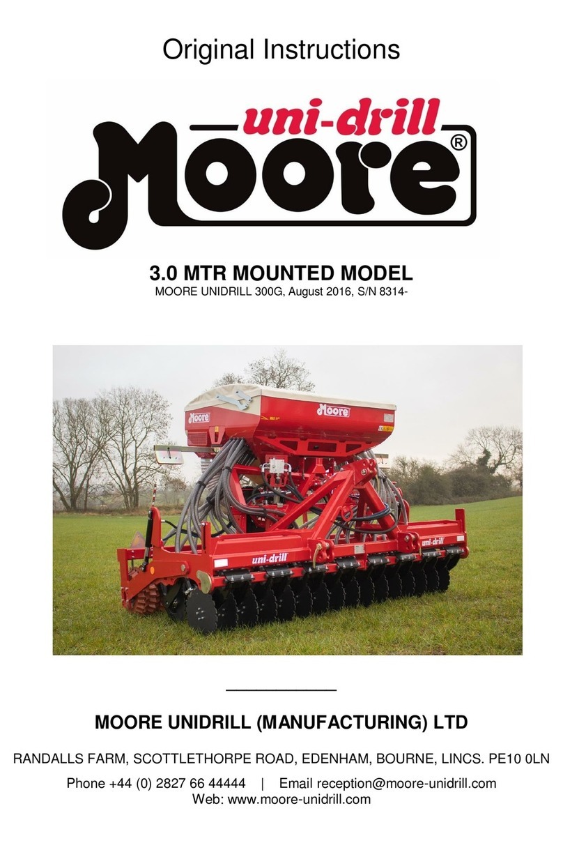
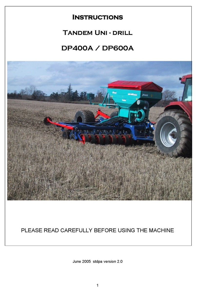
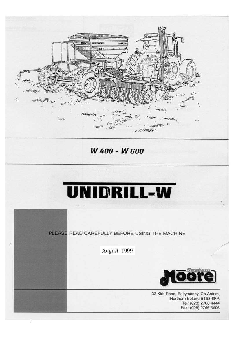
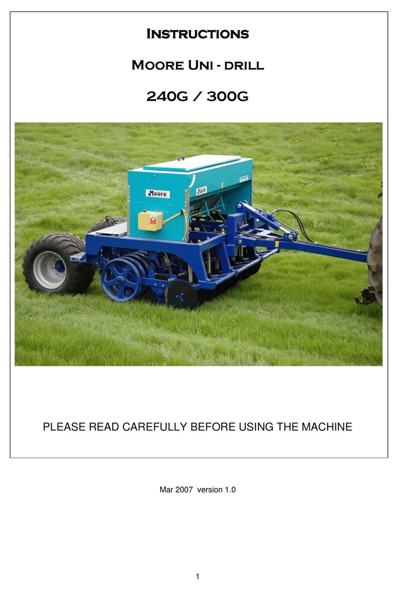
Moore UNIDRILL 300 User manual

August 2001

Thank you for trusting our equipment and choosing
the UNIDRILL.
To Ensure correct operation, and make full use of
your seed drill’s capabilities, we recommend that
you read this operators manual carefully.
Please do not hesitate to make suggestions or
comments based on your experience; they will
always be of use to us, and will help us improve our
products.
Please return the duly completed guarantee form to
us.
We wish you success with your seed drill.
Yours sincerely
Sam Moore
Managing Director
1
Dear Customer

Guarantee Form
Moore Uni Drill Limited
33 Kirk Road, Ballymoney,
Co. Antrim, N Ireland, BT53 6PP
TEL: (++44) 028276 64444
FAX: (++44) 028276 65696
Email: info@moore-unidrill.com
Website: www.moore-unidrill.com
Machine Width:
Serial Number:
Customer Name:
Tel:
Mobile No:
Email:
Address:
Post Code:
I HAVE RECEIVED THE ABOVE MACHINE IN AN ACCEPTABLE
CONDITION AND TO THE CORRECT SPECIFICATION.
I HAVE RECEIVED AND READ THE OWNERS MANUAL FOR SAFE
AND CORRECT OPERATION OF MACHINE.
I WISH TO REGISTER MY MACHINE FOR WARRANTY.
SIGNED:-
CUSTOMER DATE:-
1. To be completed, detached and returned to Moore Uni Drill within 14 days of
customer receipt / purchase.
2. It is essential that all details be completed.
3. Failure to complete and return this form will prevent claim settlement.
2

3
Declaration of Conformity
The Essential Health and Safety Regulations Directive. 98 - 37 - EC
The Proposed Seed Drills Safety Document 2000
(00 / 714171 DC)
Design Engineer
Date: 17 - 05 - 2001
DECLARATION OF CONFORMITY

4
Safety Regulations

5
Only use Moore Spare Parts.
The Pressure line of the hydraulic circuit is marked
with a red probe cover. The Return line of the
hydraulic circuit is marked with a blue probe cover.

6
Warning Symbols 1

Ensure wheel nuts are tight Ensure transport pins are used when
working under raised machine
Do not work under
raised marker Ensure the tramline system is functioning correctly after each fill
Never reach into rotating auger
25
Forward speed should not exceed 25 KPH
7
Warning Symbols 2

Safety / Instruction Decals
8

Safety / Instruction Decals
9
25

10
Technical Specifications
Identification
When accepting ownership of your machine note the following information:
Serial Number:_____________________
Type of machine:___________________________________________________________
Accessories:_______________________________________________________________
Technical Specifications
MOORE UNIDRILL 240M Grassland 240 Grassland
Width (m) 2.4 2.4
Number of rows 18 18
Row spacing (cm) 13.3 13.3
Width in transport (m) 2.4 2.4
Hopper capacity (l) 700 700
Weight (Kg) 2150 2400
Horse Power Required (HP) 90 90
MOORE UNIDRILL 300 Grassland 300M Arable 300 Arable
Width (m) 3 3 3
Number of rows 22 18 18
Row spacing (cm) 13.3 16.6 16.6
Width in transport (m) 3 3 3
Hopper capacity (l) 700 1150 1150
Weight (Kg) 2750 2500 2750
Horse Power Required (HP) 100 100 100
MOORE UNIDRILL 400 Arable
Width (m) 4
Number of rows 24
Row spacing (cm) 16.6
Width in transport (m) 4
Hopper capacity (l) 1600
Weight (Kg) 3150
Horse Power Required (HP) 120

11
Contents
Acknowledgments 1
GuaranteeForm 2
Declaration of conformity 3
SafetyRegulations 4-5
WarningSymbols1 6
WarningSymbols2 7
Safety / Instruction Decals 8 - 9
Technical Specifications 10
Contents 11-12
SECTION 1 STARTING UP
- Preparation and calibration, running in, seedbed preparation 13
- Hitching - Trailed drill 14
- Hitching - Mounted drill 15
- Transport, Hydraulic connections 16
SECTION 2 SETTINGS
-Distributionshutter,Baseflap 17
- Selecting the peg wheel, variator 18
- Preparing calibration test 19
- Carrying out calibration test 20 - 21
- Adjusting with the calculator 22
-SowingDepth 23
- Coulter height setting, tilt setting adjustment 24
-SideMarkers 25
-Sidemarkersafety 26
- Tramlining system. Principle, operation 27
-TramliningSystem.Settings 28
-Postemergencetramlining 29
- Half width shut-off, Emptying the hopper 30
SECTION 3 OPERATION
- Field operation, work rate, Drilling into a conventional seedbed 31
- Drilling in wet conditions, Drilling into trashy conditions, Min tillage, Direct drilling 32
- Direct drilling grass, preventing soil compaction 33
-Buryingthestraw 34
- Other Suggestions 35

SECTION 4 MAINTENANCE
-Points1-12 36
- Cleaning, greasing 37
- Checking and setting disc coulters 38
- Checking for signs of wear, Tyre pressures 39 - 40
SECTION 5 OPTIONAL EQUIPMENT
- MS Flow modulation. Starting up 41 - 44
-Operation 45-49
-Variator 50
- Electro diverter valve 51 - 52
SECTION 6 PARTS LIST
-Notes 53
-Dragarmseedingunit 54-55
- Dragarm axle units. Arable - Grass 56 - 57
- Drawbar and rear axle assembly 58 - 59
- Drive wheel assembly 60 - 61
- Seedbox assembly 62 - 63
- Seedbox drive unit 64 - 65
- Multiplicator 66 - 67
- MS Flow modulation 68 - 69
- Linak Actuator 70 - 71
- Seedbox metering parts 72 - 73
-SPIverticalliftmarker 74-75
- Electric parts - Sensors 76 - 77
- Electric parts - Chassis 78 - 79
SECTION 7 CALIBRATION CHARTS
- Available pre set reminders 80
- Table 1. Recommended shutter, base flap and peg wheel positions 81
- Calibration charts for wheat. Worked example 82
- Calibration charts for rape, barley, peas and field beans 83
- Calibration charts for oats, mustard, phacelia and radish 84
- Calibration charts for lucern, linseed, rye grass and clover 85
Notes 86
Warranty 87
12

Starting up Section 1
A. PREPARATION AND CALIBRATION
Attach the drill to the tractor and raise the drill to its maximum height, remove the transport
pins. Calibrate the seeding mechanism for seeds to be sown as in Section 2. Settings.
B. RUNNING IN
If the drill is new and is to be used in cultivated soil, it is better to “run-in” the drill in hard
ground, such as a grass field. It is easier to work off the paint and rough edges from the seed
tube and disc coulters when working in firm ground as there is more friction to turn the
discs. This only requires a few turns across a field without seed. The depth control of the
Uni-Drill can be tried out by 1. Retracting or extending of the depth control ram to increase
or decrease the depth of penetration. 2. Retracting or extending of the tractor top link if the
drill is mounted, Check that all discs turn relatively freely; it may be necessary to slacken
off seed tubes that are rubbing tight against the discs.
C.SEEDBED PREPARATION
It is not necessary to prepare a fine seedbed as for other drills. The Uni-Drill prepares its
own mini seedbed by using an angled disc and seed tube coulter tine. In most fields it is only
necessary to plough and perhaps level and roll. If the soils are loose, puffy soft or have loose
stones on the surface, it will generally be advantageous to roll or press the field first. This
will reduce blockages and help maintain even depth control.
Where a fine seedbed has been prepared and it gets wet then the soil acts as a sponge and
absorbs a lot of water, making it almost impossible for the drill or any other implement to
work in it. Therefore it is better to consolidate loose seedbeds soon after any tillage, so that
they will not absorb so much water. The drill will work on most consolidated seedbeds
provided the drill is being used at speed. At a speed of over 6 MPH the centrifugal force on
the discs and rollers tends to fling the sticky soil from them; just like driving a tractor along
a road, where the dirt on the tyres is thrown off when it reaches a certain speed.
13

Position 1
Position 2
14
Starting up
To unhitch the seed drill, set the machine in the working position
HITCHING
Trailed drills
Hitching Height
The height of the hitching point greatly
affects the machines correct operation
(+/- 450 mm)
- The hitching point must importantly be
fixed. The lower linkage bar cannot be
used in this case.
- Low hitching heights should be
preferred, such as the pick up hitch or
clevis drawbar especially for direct
sowing.
- The clevis drawbar is recommended
when using dual wheels or wide tyres
to make manoeuvres at the field ends
easier.
Locking the drawbar
2 drawbar locking positions are available.
- Position (1) is the normal working
position.
- Position (2) is used if position (1) is
ineffective on hard ground, or if the
seed drill’s penetration is insufficient.

Starting up 3 Point Linkage Machine
HITCHING
Mounted drills
1). When hitching or unhitching the
machine from the tractor, place the
lift control lever in such a position
that the lifting mechanism cannot be
activated accidentally.
2). When hitching the machine to the
three point linkage, ensure that the
diameters of the pins correspond to
the diameters of the lift arm ball
ends.
3). Caution! In the three point lifting
zone there may be a danger of
crushing and sheering.
4). Do not stand between the tractor and
the machine whilst operating the
external lift control lever.
5). When in transport the lift arm stabilizer
bars or check chains must be tight to
avoid floating and side movement.
6). When transporting the machine in the
raised position, lock the lift control
lever.
Depth Adjustment
Depth adjustment is obtained by adjusting
the length of the tractor top link. As the
top link is shortened / lengthened the
deeper / shallower the sowing depth can
be achieved.
15

16
2
1
Starting up
The user must comply with road traffic regulations. The hopper should be empty
when driving on the road, at a maximum speed of 25KPH.
TRANSPORT
Positioning the pins (1) in their
transport position.
- Raise the seed drill
- Insert the locking pins
- Lower the machine so that it rests on
the pins.
HYDRAULIC
CONNECTIONS
Double-action hydraulic system to lift the
seed drill.
Double-action hydraulic system for depth
control
Single-action hydraulic system controlling
side-markers and tramlining system.
Install the hydraulic hoses on support (2)
The pressure lines are marked with red
probe covers.
The return lines are marked with blue
probe covers.

17
Settings Section 2
SETTINGS
Distribution settings. (Please refer to
section 5).
1) Distribution shutter.
Raise or lower the shutter (1) according to
the recommendations. Insert the spring
(2) into the appropriate catch.
3 opening positions are available for the
shutter.
Marker 0. Closed (when sowing every
2nd row for instance).
1. Small seeds < 8kg/ha
2. Large seeds.
Follow the setting instructions
2) Base Flap
Move the lever (3) slightly to the right and po-
sition at the appropriate marker.
Marker 1. Cereal. 1st Wheats only.
2.
3.
4. Peas for canning.
5. Peas.
6. Beans.
Max. Lower Position. Hopper Emptying
The aim is to have the seeds metered out by
the peg wheel with the base flap open as
little as possible (eg marker 1 for wheat and
barley). However if you notice constant
projections of seed from the distribution
system, position the lever one marker above
the recommended setting.
(eg marker 2 for wheat and barley).

18
Settings
SETTINGS
3) Selecting the peg wheel
(1) standard wheel for cereal and large
seeds.
(2) fine wheel for small seeds
Take hold of the pin located on the
shutter of the first unit to the right.
To select the distribution wheel:
A) Press
B) Turn
1. Small seeds < 8kg/ha
2. Large seeds.
Follow the setting instructions
4) Variator
Using the knob (3) and the lever, position the
marker according to the results of the
calibration test (4).
Read the settings above the flat part (5)
Each marker adjustment must be followed by
a calibration test. For your information, 3
graduations on the adjustment scale equals a
10 kg/ha increase/decrease with cereal.
Scale range from 0 to 90.

19
Settings
SETTINGS
Preparing the calibration test
- Use accurate scales and a container.
- Before carrying out the test, check that
no-one is standing near the seed drill
except the operator.
Procedure
- Open the trays (1) and (2) and push
them down and forward in order to lower
them below the distribution points.
- Fit the calibration handle (3) onto the
variator shaft.
- Check that the distributions in use are
engaged.
- Perform your calibration test according to
the recommendations issued in the
following pages.
- To empty the seeds from the tray more
easily, open the flap slightly lifting the
lever (4).
- Raise the trays back into guard position.
Very precise sowing requires a calibration test. Make sure your scales are accurate.
This manual suits for next models
1
Table of contents
Other Moore Farm Equipment manuals
Popular Farm Equipment manuals by other brands

burchland
burchland XTS Operator's & parts manual

Claas
Claas 930 Information and Basic Field Settings

LUCLAR INTERNATIONAL
LUCLAR INTERNATIONAL MiniStraw UNIBALL 1500 Use and maintenance

Walinga
Walinga AGRI-VAC 5614 OPERATOR'S MANUAL AND PARTS BOOK

Dion
Dion F61 Operator's manual

Kubota
Kubota RA1042T Operator's manual