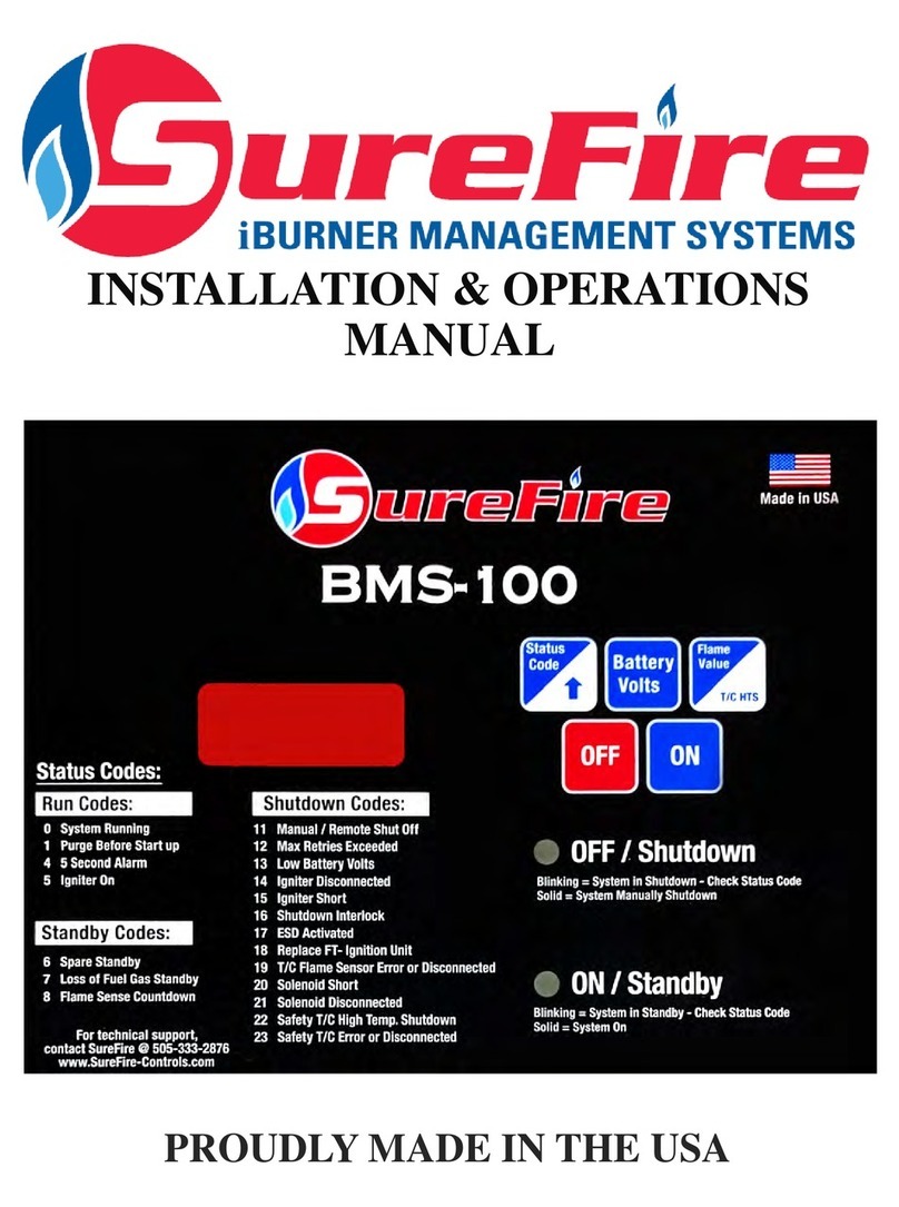
Surefire BMS-350 User manual

PROUDLY MADE IN THE USA
INSTALLATION & OPERATIONS
MANUAL

2
TableofContents 2
SystemIntroduction 3
Certification and Warnings 4
WarrantyandReturnPolicy 5
SystemDescription 6-9
Product Information 10 - 13
Installation Guide 14 - 18
Specifications 19
Run Status and Flame Strength Information 20
Diagrams 21 - 22
SystemSetup 23-28
Sequence of Operation 29 - 34
Troubleshooting Information 35 - 38
Modbus Information 39 - 47
SoftwareVersions 48
Notes 49-51
Table of Contents

3
The BMS-350 is designed for heavy duty oilfield applications and is certified to UL and ISA
standards for hazardous areas. The BMS-350 is designed to operate with the FT Ignition units
to provide optimal ignition.
The controller’s display is designed to operate in ambient temperature from –40°F to 131°F,
and is coated for corrosion resistance. The unit is mounted in a NEMA 4X enclosure supplied
with a UV resistant keypad. Each unit includes function indicator lights and a status code chart
printed on the overlay to provide assistance in troubleshooting. The unit requires 12 VDC
power and is solar ready with a specific solar power termination port.
This Burner Management System is suitable for use in Class 1, Division 2, Groups C and D,
T6 Hazardous (Classified) and Ordinary Location.
The system monitors target temperature with an enhanced RTD or Thermocouple circuits and
indicates temperatures from 0°F to 490°F (RTD) and 32°F to 2700°F (Thermocouple). The
system controls both the pilot and main burner gas valves as necessary and is designed as a fail
safe system. High temperature and flame failure shutdowns are available along with an audible
startup warning. The system’s fail safe run status alarm function allows for remote monitoring
for environmental and regulatory compliance. Standard remote features include temperature
indication, remote ON and OFF utilizing an RTU or PLC, and Modbus read only
communication through RS-485 or RS-232.
The BMS-350 process may also be controlled using the alt sense input. Multiple connections
for additional standby and shutdown requirements are also provided.
Every SureFire system must pass complete factory QA/QC inspections before shipment.
We are dedicated to providing quality, American-made safety control systems
for industrial burners. The system has been developed through thousands of
hours of critical design, engineering, and field testing.
BMS-300 System Introduction

4
ETL Certified to the Following
Standards:
CERTIFIED TO:
CSA STD C22.2 NO. 61010-1
CSA STD C22.2 NO. 213:2017 Ed.3
*WARNING*
EXPLOSION HAZARD – SUBSTITUTION OF COMPONENTS MAY IMPAIR
SUITABILITY FOR CLASS I, DIVISION 2;
*AVERTISSEMENT*
RISQUE D'EXPLOSION – LA SUBSTITUTION DE COMPOSANTS PEUT RENDRE CE MATERIEL
INACCEPTABLE POUR LES EMPLACEMENTS DE CLASSE I, DIVISION 2
*WARNING*
EXPLOSION HAZARD - DO NOT REPLACE FUSES UNLESS POWER HAS BEEN SWITCHED OFF
OR THE AREA IS KNOWN TO BE NON-HAZARDOUS;
*AVERTISSEMENT*
RISQUE D'EXPLOSION - COUPER LE COURANT OU S'ASSURER QUE L'EMPLACEMENT EST
DESIGNE NON DANGEREUX AVANT DE REPLACER LE FUSE.
*WARNING*
EXPLOSION HAZARD - DO NOT DISCONNECT EQUIPMENT UNLESS POWER HAS BEEN
SWITCHED OFF OR THE AREA IS KNOWN TO BE NON-HAZARDOUS;
*AVERTISSEMENT*
RISQUE D'EXPLOSION - AVANT DE DECONNECTER L'EQUIPEMENT, COUPER LE COURANT OU
S'ASSURER QUE L'EMPLACEMENT EST DESIGNE NON DANGEREUX.
*WARNING*
EXPOSURE TO SOME CHEMICALS MAY DEGRADE THE SEALING
PROPERTIES OF MATERIALS USED IN THE FOLLOWING DEVICES: PANASONIC RELAY, MOD-
EL JW2SN-DC12V, AND HAMILIN RELAY, MODEL HE721A0500
*AVERTISSEMENT*
L'exposition à certains produits chimiques peut dégrader les ETANCHEITE
Propriétés des matériaux utilisés dans les dispositifs suivants: RELAIS PANASONIC MODÈLE JW2SN-
DC12V, ET RELAIS HAMILIN, MODÈLE HE721A0500
7.8 amps @ 12.0 vdc MAX
0.025 amps @ 12.0 vdc AVG
CONFORMS TO:
UL STD 61010-1
UL STD 121201:2017 Ed.9
Certifications and Warnings

5
Warranty and Return Policy
SureFire Warranty Statement:
SureFire warrants all equipment of its own manufacture to be free of defects in material and workmanship. SureFire’s
sole obligation hereunder shall be expressly limited to repair or exchange, F.O.B. Farmington, NM, USA of such
defective equipment, but does not apply to claims which are a result of improper installation, misuse, maladjustment,
abnormal operating conditions, or lack of routine maintenance as determined by SureFire. Nor does the warranty
include the furnishing of service for maintenance or problems arising from the foregoing causes. No claims for labor,
installation, removal, transportation, or other expenses will be recognized. Notwithstanding any stipulation of the
purchaser to the contrary, all other obligations, representations, warranties and conditions, express or implied, statutory
or otherwise, including any implied warranties or conditions of merchantability, quality or fitness are hereby excluded
and, SureFire shall not be liable for any loss, cost or damages, of any kind whatsoever, whether consequential, indirect,
special or otherwise, arising out of or in connection with the equipment or any defect therein, even if caused by the
negligence of SureFire, its employees or agents. The provisions hereof relating to the warranty and limitations hereon
and limitation of liability shall continue to be enforceable between the parties notwithstanding termination of the within
agreement for any reason including fundamental breach. Equipment not of SureFire manufacture shall pass through to
the original manufacturer’s or vendor’s warranty.
The warranty policy is related to manufacturing defects. The return policy is related to the return of product for any
reason other than manufacturing defects. Returns must be approved by SureFire in advance of shipment and returned
products must be in their original condition. Restocking fees for returns are at the discretion of SureFire and may vary
by product.
Shipping Cost:
For Warranty Claims, the shipping cost incurred by shipping the product from the customer to SureFire will be at the
expense of the customer. If the product is deemed under warranty by SureFire, then the shipping cost incurred by
shipping the product from SureFire to the customer will be at the expense of SureFire. If the product is deemed
non-warranty by SureFire, then the shipping cost incurred by shipping the product from SureFire to the customer will
be at the expense of the customer.
Product Description Warranty Policy
Defective Products
Return Policy
Customer Return New Product
SureFire Controllers:
BMS-300, BMS-100, Flare-100
and BMS-350 Controllers
3 Years from date of purchase 180 Days from date of purchase
20% Minimum Restocking Fee
SureFire FT Ignition Units:
FT-1, FT-2, FT-4, FT-6 and
FTL-F Ignition Units
2 Years from date of purchase 180 Days from date of purchase
20% Minimum Restocking Fee
Additional Components
Manufacturers carry own
individual warranty policy on
Components.
Manufacturers carry own
individual return policy on
Components.

6
The SureFire BMS-350 System uses a polycarbonate NEMA 4X enclosure to house the circuit board. The
graphic overlay with membrane keypad is mounted on the exterior of the enclosure.
The NEMA 4X enclosure provides a high level of protection from harsh outdoor elements:
Windblown Dust Protection
Water Damage Protection - Rain, Sleet, Snow, Splashing and Direct Water Contact
Corrosion Protection
External Formation of Ice Protection
The Enclosure is IP66 certified and has been tested to the following to meant certification:
Dust tight, no ingress of dust; complete protection against contact
Water projected in powerful water jets (12.5mm nozzle) against the enclosure from any direction
shall have no harmful effects.
WARNING:
When drilling holes in the enclosure, ensure IP66 fittings are used to maintain the IP66 standard.
Failure to use IP66 standard fittings nullifies the IP66 certification.
Enclosure:
BMS-350 Description

7
BMS-350 Circuit Board:
The SureFire BMS-350 System is controlled by state of the art, non-arcing electronics, that monitor and
control all burner functions. It comes with 4 LED indicators and a LED Display. It also comes with
individual terminal blocks, ground lug, and power connector to ease wiring and installation.
BMS-350 Description

8
Graphic Overlay:
The overlay is used for interfacing with the system to acquire system data. The overlay also provides a list of
status codes and a display window that shows data, settings, and information.
LED Indicator Status
GREEN LED ON - Indicates that the system is on and operating properly
Blinking - Indicates a standby switch has been activated
RED
LED ON - Indicates that the system is off
Blinking - Indicates a shutdown switch has been activated
AMBER LED ON - Indicates igniter is on.
Blinking - Indicates an igniter failure.
BLUE LED ON - Indicates a flame has been sensed on the flame sensing device
LED Indicators:
The circuit boards LEDs illuminate through the lid of the enclosure. The LED’s indicate the following:
BMS-350 Description

9
16 Button Keypad:
The SureFire BMS-350 System has a 16 button keypad to control and monitor the system. The buttons
perform the following functions:
Button Displayed Value / Functional Operation
Up Arrow Increases the current value
Press and hold for 5 seconds to unlock. A series of zeros will appear on the screen.
Down Arrow Decrease the current value
Press and hold for 5 seconds to relock the system
High Temp
Displays the High Temperature setpoint
While in locked mode, press and hold for 5 seconds to display the Safety Thermocouple’s
current temperature
Low Temp Displays the Low Temperature setpoint
Flame Sense Displays the current Flame Sensing device:
F = Flame Rod H = Thermocouple
Temp Control Displays the current Temperature Control device:
A = Alt Sense 1 = RTD 2 = Thermocouple
Status Code Displays the code that corresponds with the current unit’s status
Press and hold and use the Up or Down Arrows to display the system’s past 9 codes
EHTD Displays the current Extreme High Temp Delta setting
Battery Volts Displays the current voltage being supplied from the battery to the BMS-350 system
Pilot Mode Displays the current Pilot Mode
1 = Intermittent Pilot 2 = Standing Pilot
FPT Displays the current timing between Stage 1 Solenoid and Stage 2 Solenoid Valves
Flame Strength Displays the current Flame Strength value
Press and hold for 5 seconds to display the Safety Thermocouple shutdown setpoint
AUX
Displays current Igniter Ohm value
Press and hold to display the following data
System Days On
Burner Days On
Ignition Attempts
Successful Ignition
OFF Turns the system OFF
ON Turns the system ON
BMS-350 Description

10
SureFire Ignition Units
For proper pilot placement and flame sensing selection, contact SureFire Tech Support @
505-333-2876 or the local SureFire representative
SureFire FT-Series Ignition Units:
The SureFire BMS-350 is compatible with the listed FT series
igniters. Each unit is designed for specific Flare, Combustor and
Fire Tube applications. The FT series ignition units have been
designed for both piloted and pilotless applications.
Flare / Combustor Pilot System:
The FTL-F series Ignition units are designed for Flare and
Combustor applications, utilizing a thermocouple as a flame
sensor.
Piloted System:
The FT-1 Ignition units are designed for piloted applications,
utilizing the thermocouple or flame rod flame sensing device. The
FT-1 Ignition units are used in a piloted application with burners
ranging from 125,000 BTU/HR to 10 MM BTU/HR.
Optional Flame Sensors:
Thermocouple (recommended)
Utilizes temperature reading to verify the presence of a flame
Armored wiring harness rated to 1000°F duty and 1500°F flash
Direct termination to the BMS-350 Controller
Flame Rod:
Kanthal flame rod rated 2600°F
Armored wiring harness to 500°F duty / 800°F flash
Direct termination to BMS-350 controller

11
Pilotless System:
The FT-2, FT-4 and FT-6 Ignition units are designed for
pilotless applications with a flame rod flame sensing
device. These three ignition units are used in pilotless fire
tube applications for horizontal treaters with the following
BTU/HR burner ratings.
FT-2 Systems (1”) are rated for 125,000BTU/HR
FT-4 Systems (2”) are rated for 500,000BTU/HR
FT-6 Systems (3”) are rated for 1,000,000BTU/HR
The FT-4-VT and FT-6-VT ignition units are designed for
pilotless application for vertical treaters and have the
same BTU/HR burner ratings as above.
Thermocouple
Utilizes temperature reading to verify the presence of
a flame
Armored wiring harness rated to 1000°F duty and
1500°F flash
Direct termination to the BMS-350 Controller
Flame Rod:
Kanthal flame rod rated 2600°F
Armored wiring harness to 500°F duty / 800°F flash
Direct termination to BMS-350 controller
For proper pilotless ignition unit and orifice sizing, contact tech support @ 505-333-2876 or the local
SureFire representative
SureFire Ignition Units

12
1” & 2” SureFire Solenoid Valve:
Fail-closed device.
No adjustment necessary.
Simple termination and installation.
Kalrez elastomer plunger.
Plunger replacement kits available.
Applications include– non-venting pilotless fuel trains,
double block fuel trains, fuel trains for combustors and
flares systems.
1” SureFire Actuator:
Control the main fuel gas to the main burner.
Factory programmed and pre-wired so no adjustment is
necessary.
3 wire termination.
Proof of valve closure switch kit available
Applications include– non-venting pilotless fuel trains,
double block fuel trains, fuel trains for combustors and
flare systems.
SureFire Additional Components

13
1/4” ASCO Solenoid Valve:
Fail closed device.
No adjustment necessary.
Simple termination and installation.
Applications include– direct pilot (#72 orifice) and
pneumatic valve operation.
1/2” Pressure Switch:
Used on a variety of standbys and shutdowns
Can be set as normally open or normally closed.
Adjustable from 1 psi — 15 psi.
316 SS construction, wetted parts are NACE
1/2” Resistance Temperature Detector:
Detects the process temperature.
Simple three wire termination.
Available in: 5”, 6”, 9”and 12”
1/4” Slow Flow Valve:
Reduces the inrush of fuel gas into the diaphragm
valve for smooth and reliable ignition.
Required on all pilotless installations when not
using an actuator valve.
Recommended for piloted installations
SureFire Additional Components
Thermocouple, Type K:
Detects the process temperature.
Simple two wire termination.
Available in: 6”, 9” and 12”.

14
SureFire BMS-350 Enclosure:
1. The enclosure is to be mounted on to a pole or a building that is capable of supporting 10 lbs.
2. Position the enclosure so that the LED display is clearly visible for the operator.
3. Install conduit seal-off fittings for all electrical connections to the enclosure.
4. Installation must comply with the national electric code.
WARNING:
Before any welding is attempted, disconnect all wires going to the circuit board. Any damage caused by
welding to the SureFire BMS is NOT covered under warranty.
Before terminating any wires ensure no power is supplied to the controller.
Any damage caused by standing on or using the enclosure as a step is NOT covered under warranty.
Installation Guide
SureFire FT-Series Ignition Unit:
1. Ensure supply gas is turned off and locked out/ tagged out.
2. Install the FT unit in fire tube or proper flare / combustor position.
3. The igniter has two white wires that are not polarity sensitive. Terminate wires to ports 30 & 31. See
illustration below.
For proper FT unit positioning, contact tech support @ 505-333-2876 or
the local SureFire representative
Flame Rod Flame Sensing:
Piloted and Pilotless ignition units are wired the same as below.
1. Terminate flame rod wire at designated port on upper left hand corner
of the circuit board. The port is labeled as “Flame Rod”.
2. Isolated grounding is required. Terminate ground wire to circuit board
labeled Earth Ground and ground screw on GUA on arrestor housing.
3. Flame sensing switch needs to be on Flame Rod.
NOTES:
Please do not bond the flame sensing ground to facility ground to
avoid flame sensing disruption.

15
Piloted System:
1st and 2nd Stage Solenoid Valve
1. Ensure main supply gas is shut off.
2. Locate the pilot gas supply line and instrument gas supply line
controlling the main burner control valve.
3. Install 1st stage solenoid down stream of the pilot regulator.
4. Install 2nd stage solenoid in the appropriate location to
actuate the main burner control valve.
5. Cut and bend custom 3/8” tubing and connect to tubing
fittings on solenoids.
6. Terminate 1st and 2nd stage solenoid wires.
NOTES:
ASCO Solenoid proper flow direction: 2 = Inlet and 1 = Outlet
Installation Guide
Flame Sensing - Thermocouple:
1. Thermocouple flame sensing terminate the red (-) wire and
yellow (+) wire to the designated ports labeled Thermocouple in
the upper left corner of the circuit board.
Pilotless System:
SureFire Actuator Valve & 1st Stage Solenoid Valve
1. Ensure main supply gas is shut off.
2. Locate the pilot gas supply line and eliminate the pilot fuel train completely.
3. Install the SureFire Actuator Valve in the fuel train on the main burner line down steam of the main
burner control valve.
4. Locate the instrument gas supply line controlling the main burner control valve and install 1st stage
solenoid in the appropriate location to actuate the main burner control valve.
5. Cut and bend custom 3/8” tubing and connect to tubing fittings on the solenoid valve.
6. Terminate 1st stage solenoid wires to ports 8 & 9.
7. Terminate Actuator wires at terminal block labeled Actuator Valve (1, 2 & 3) from the Actuator Valve
terminals (1, 2 & 3).

16
RTD:
1. Install the RTD into the provided thermowell on
the vessel for process temperature.
2. Connect negative (-) wires to terminals 10 & 11.
3. Connect positive (+) wire to terminal 12.
NOTES:
Software version 2.73 and above. When system recognizes temperature at 4ºF or less, press ON button
and a 30 minute timer starts. If system does no recognize a temperature increase above 4ºF, the system
will shutdown on code 18. Repeat until temperature gets above 4ºF.
Installation Guide
Pilotless System:
SureFire Actuator Valve & 1st Stage Solenoid Valve
NOTES:
Terminal block 1 @ SureFire Actuator port 1
Terminal block 2 @ SureFire Actuator port 2
Terminal block 3 @ SureFire Actuator port 3
Must use a SureFire Actuator valve or an actuator
approved by SureFire.
ASCO Solenoid proper flow direction: 2 = Inlet and 1 =
Outlet
Thermocouple - Process Temperature
1. Install the Thermocouple into the provided thermowell
on the vessel for the process temperature.
2. Connection the positive (+) wire (yellow) to the
positive terminal, (Port 13).
3. Connect the negative (-) wire (red) to the negative
Thermocouple - High Temperature Shutdown
1. Install the thermocouple in the provided thermowell.
2. Connection the positive (+) wire (yellow) to the positive terminal, (Port 15).
3. Connect the negative (-) wire (red) to the negative terminal, (Port 16).
NOTES:
If this port is unused, insert a jumper into the port.

17
Installation Guide
Standby Ports:
When using a device, install a normally open or closed
dry contact device into ports and 20 & 21 and 22 & 23.
If no device is used, a jumper is required on afore
mentioned ports.
NOTES:
Closed contact = Normal operation
Open Contact = Failed operation
Shutdown Ports:
When using a device, install a normally open or closed
dry contact device into ports and 24 & 25 and (proof of
valve closure) 26 & 27.
If no device is used, a jumper is required on afore
mentioned ports.
NOTES:
Closed contact = Normal operation
Open Contact = Failed operation
4-20mA / 1-5 Volt
For standard 4-20mA: Connect the positive wire from
the remote monitoring equipment to port # 5 and the
negative wire to port # 4
For 1-5 Volt: Connect the positive wire from the remote
monitoring equipment to port # 5. Then install a 250
resistor in series with the negative wire and terminate to
port # 4.
RTD SCALING:
4-20mA: 4mA = 0°F 20mA = 670°F
1-5 Volt: 1 Volt = 0°F 5 Volt = 670°
THERMOCOUPLE SCALING:
4-20mA: 4-20mA = 32°F 20mA = 2400°F
1-5 Volt: 1 Volt = 32°F 20mA = 2400°F

18
Installation Guide
Run Status:
1. Terminate the wires from the RTU / PLC to
the Run Status terminal ports # 4 & 5
Alarm Output:
1. Terminate the wires from the RTU / PLC to
the Alarm Output terminal ports # 6 & 7.
Solar Panel Input:
1. Install 12 VDC Solar Panel on a pole or a
building and face it south.
2. Connect negative terminal to port # 32
3. Connect positive terminal to port # 33
NOTES:
Maximum rating for solar panel is 75 watts
The circuit board is internal charge controller
to charge 12 VDC battery.
12 VDC Battery Input
1. Install 12 VDC SLA battery.
2. Connect negative terminal to port # 34
3. Connect positive terminal to port # 35
NOTES:
If the battery is more than 10’ away from the
SureFire controller, use larger AWG wire as
needed.
If utilizing a 12 VDC power supply, set volt-
age @ 13.4 VDC. The power supply should
be rated for 75+ Watts.

19
Specifications
Power Supply Specifications
Battery 12 VDC - 14.5 VDC
12 VDC Power Supply Set @ 13.4 VDC
Solar Panel 12.0 VDC Only - 75 Watt Max
24 VDC 24.0 VDC
Ignition Unit Specifications
Igniter Current Draw 7.5 Amps Inrush, 2.0 Amps NOM (During
Normal Operation)
Sensor Specifications
RTD 0°F - 670°F
Thermocouple 32°F - 2,400°F
Alt Sense Switch Dry Contact Switch (Open / Close Loop)
Standby / Shutdown Switches Dry Contact Switch (Open / Close Loop)
Output Specifications
4 - 20mA 12 - 24 VDC for 4 - 20mA Output
12 - 24 VDC @ 1 Amp
Max Volts: 26 VDC, Max Current: 1 Amp
Alarm (Output) 12 - 24 VDC @ 1 Amp
Power Supply and Igniter Wiring Requirements
14 AWG @ 20’
Note: If distance from battery (Power Supply)
is further than 20’, a large gauge of wire is
required.
Run Status (Output)
Max Volts: 26 VDC, Max Current: 1Amp

20
Run Status Operational States:
Run Red
Open ON
Close OFF
Close OFF
Open Blinking
Green
OFF
ON
ON
OFF
Blue
OFF
OFF
ON
OFF
Operational State
System OFF or Manual
Shutdown
System ON, Pre-purge
complete, igniter on
Flame sensed, Burner
running, No Errors
Shutdown, Igniter Error
Amber
OFF
ON
OFF
Blinking
Standby Error Close OFF Blinking OFF OFF
Shutdown Error Open Blinking OFF OFF OFF
Alarm Out
Open
Open
Close
Open
Open
Close
Flame Strength Value Information:
Flame Rod No Flame Present Flame Present
Flame Strength Value Above 500 Below 6
Run Status and Flame Strength Information
Thermocouple No Flame Present Flame Present
Thermocouple flame sensing displays actual temperature, so “flame present” and “no flame
present” values may vary.
Flame strength value 70
If the T/C sees an increase
of 20 from the “snap shot”
value, a flame is sensed.
If T/C value is greater than 800, must see a 10% decrease to lose a flame.
If the T/C value is less than 800, must se a 5% decrease to lose a flame.
Other manuals for BMS-350
1
Table of contents
Other Surefire Security System manuals