Moralwinhk P168 User manual

- 1 -
GPS
GPS
Tracker
Tracker
For Vehicle
<GPS+GSM+SMS/GPRS>S
User Manual
V1.0
By www.moralwinhk.com
Model:P168
Appearance
GPS Tracker

- 2 -
Welcome to use our terminal,please read
this manual carefully to install and operate the
terminal exactly. This user manual is for
reference only. If some contents and operation
steps are inconsistent with those for the actual
product, the latter will prevail.
Using TK116 GPS tracker, we can
position、monitor and control the vehicle on
the position server via GPRS、GPS and
Internet. It can help customers to manage
transparently、reduce cost、maintain
security and raise efficiency. Now it is widely
used in business traffic、logistics
distribution、sautomobile lease、intelligent
transportation、shipping market、army and
police、rescuing、Safety
Supervision 、Intelligent city…

- 3 -
Catalog
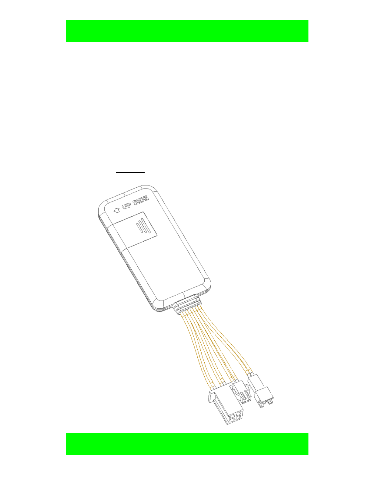
Ⅰ. Product Features ..................................1
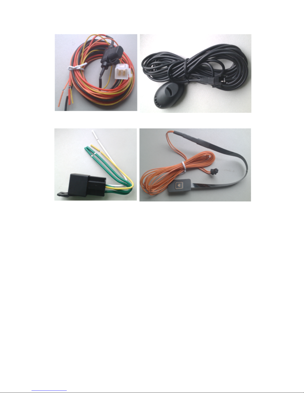
Ⅱ. Components and Accessories ..............2
Ⅲ. Environment for use..............................3
Ⅳ. Technical Specifications .......................4
4.1 Basic Specifications:...................4
4.2 LED Indicators ...............................4
Ⅴ. Installation.............................................5
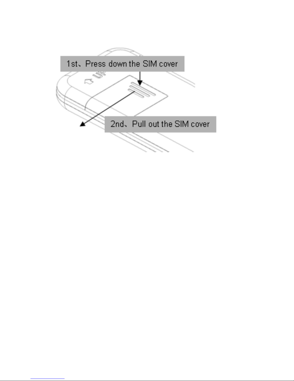
5.1 Before Installation ..........................5
5.2 Install the terminal ..........................9
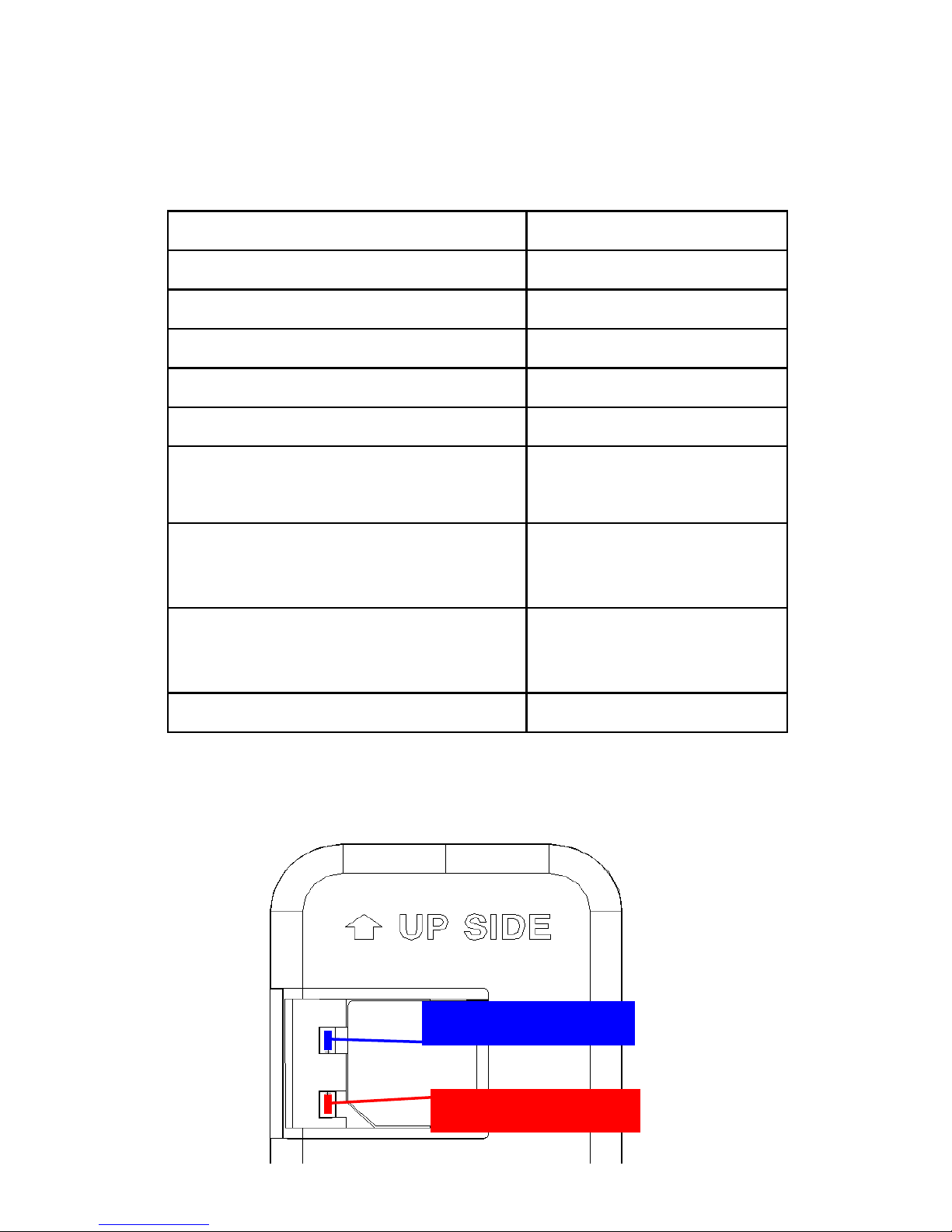
5.3 Terminal wiring definition ..............11
5.4 Terminal wiring diagram................14
Ⅵ. Attentions for wiring ............................17
6.1 Power cables...............................17
6.2 External MIC................................17
6.3 SOS cables .................................18
Ⅶ. Set up the terminal..............................18
Ⅷ. Use the terminal..................................18
8.1 Power on.....................................18
8.2 LED indicators .............................18

- 4 -
8.3 Inquiry position.............................19
8.4 SOS alarm...................................19
8.5 Monitor........................................19
8.6 Cut off the fuel pump connection ...20
8.7 Recover the fuel circuits................20
Ⅸ. Login the position server.....................20
Ⅹ. Trouble shooting .................................21
10.1 Cannot connect to the position
server ...............................................21
10.2 Show offline status on the position
server ...............................................22
10.3 Cannot position for a long time ....23
10.4 Position drift is serious ................23
10.5 Instructions receiving abnormally .24
Ⅺ. Warranty rules.....................................24
11.1 Special statement.......................24
11.2 Warranty period .........................25
11.3 After sales .................................25
Customer’s Information .............................26

- 1 -
Ⅰ. Product Features
■Supports quad bands,
i.e. 850/900/1800/1900MHz,
universal in the world.
■Wide Input Voltage:6-36V DC.
■Supports single positioning and feedbacks
position via GPRS at setting times.
■Supports vehicle positioning and tracking.
■Supports ACC status checking and vehicle
status notifying.
■Use relay to remote control the vehicle..
■Use SOS button for SOS call.
■Use external MIC to monitor remotely.

- 2 -
Ⅱ. Components and Accessories
■Components
-Top Front-
-Top Back-

- 3 -
■Accessories(reference pictures)
Power Cables(Fault)Micphone(Optional)
Relay(Optional)SOS Cables(Optional)
Ⅲ. Environment for use
1. Limited working temperature:-20℃~80℃
2. Storage temperature:-45℃~90℃
3. Humidity:<95%
4. Make sure the terminal is installed in rainproof
and snow-proof places.

- 4 -
Ⅳ. Technical Specifications
4.1 Basic Specifications:
Voltage
12VDC/24VDC
Standby Current
<3mA
Work current
<30mA
GPS positioning accuracy
15m
GSM positioning accuracy
100m
GPS Frequency
1575MHz
GSM Frequency
850/900/1800/190
0MHz
Hot/warm/cold start time
<3s,<15s,<60
s
Dimensions (mm)
L*W*H:79.5X38.
5X10.5
Net Weight
45 g
4.2 LED Indicators
Blue LED/GPS
Red LED/GSM

- 5 -
4.2.1 Red LED(indicates GSM working state)
fast flicker
Searching for GSM
network
intermittently flicker
GSM/GPRS works
normally
4.2.2 Blue LED(indicates GPS signal state)
fast flicker
Searching GPS
Satellites
intermittently flicker
GPS works normally
Ⅴ. Installation
5.1 Before Installation
5.1.1 Open the packing case, then check if the
terminal is Ok and the accessories are intact, or
please contact your dealer;
5.1.2 Choosing a SIM card: You need a suitable
SIM card for using the terminal, please contact your
dealer if you have any question;
5.1.3 Install the SIM card: First use your thumb to
press the SIM card cover, then push it outside to
pull down the SIM card cover. Now you can insert
your SIM card to the SIM card connector until you
cannot move the card inside anymore.

- 6 -
5.1.4 Uninstall the SIM card:Lift up the edge of
the SIM card, next pull it out.
●Pull down the SIM cover(three steps)

- 7 -
●Install SIM Card(two steps)
First. Insert the SIM card until cannot move it inside
anymore;
Second. Pull the SIM card back a bit;

- 8 -
●Uninstall the SIM card
First. Lift up the edge of the SIM card;
Second. Pull out the SIM card.
5.1.4 Notice
●Please cut off the power before installing or
uninstalling the SIM card.
●The SIM card should support GPRS and the
GPRS should be opening.
●Inquiry by call needs the SIM card supporting the
calling line identification presentation.
●If you enable the PIN code of the SIM card,

- 9 -
please use your mobile phone to disable the PIN
code.
●Please make sure that the SIM card has sufficient
balance.
5.2 Install the terminal
5.2.1 Suggest to install the terminal concealed by
the dealer designated professional body.
Please make sure to install the terminal with this
side upward, and use wide strong double-sided
adhesive sponge to fix it.

- 10 -
Please make sure to install the terminal with this
side towards the ground, and use wide strong
double-sided adhesive sponge to fix it.
5.2.2 Notice
●Hide the terminal properly inside the car body in
order to avoid damages.
●Keep the terminal away from RF emission
sources such as backing radar、car burglar alarm
and other vehicle mounted communication devices.
●Suggest to use wide strong double-sided
adhesive sponge to fix it, or use cable ties and
other liable methods to fix it.
●Make sure the face upward as the terminal has
internal GPS and GSM antenna and without metal
blocks. Suggest to install the terminal in the
following places:
1)The hiding place below the front windshield trim
panel;
2)The hiding place around the front dash(if the
surface is not made of metal);
3)The place under the rear windshield;
Notice: The GSM and GPS signal may be

- 11 -
weakened if there is metal thermal insulation layer
or heating layer on the front windshield, the terminal
may work abnormally, so please change the place
to install the terminal.
5.3 Terminal wiring definition

- 12 -

- 13 -
5.3.1 Power cables and other interface for remote
control

- 14 -
5.3.2 Other accessories’ interfaces
5.4 Terminal wiring diagram
Relay wiring diagram shows how to wire the relay to
control the fuel pump:
5.4.1 Connect the 85 terminal(with small white
cable) to the positive pole of the vehicle power
(+12V/+24V), connect the 86 terminal(with small
yellow cable) to the 4# cable of the terminal.
5.4.2 Cut off the positive pole of the fuel pump, next
serial connect the positive pole to the 87a

- 15 -
terminal(with think green cable) of the relay, and
connect another pole to 30 terminal(with think green
cable), showing as in the figure.
Notice: Be sure that the voltage of the vehicle
power should match up to the working voltage of
the relay, or the relay will be damaged.
Relay Wiring:
Bottom of the relay

- 16 -
-Wiring Diagram
Table of contents