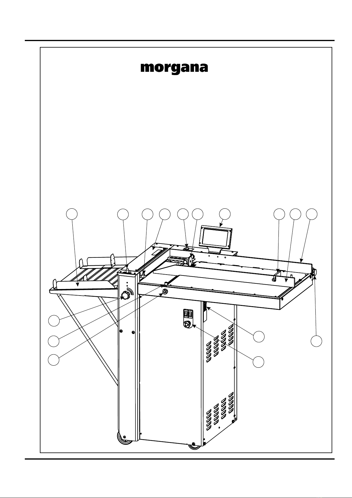
Morgan AutoCreaser Pro 50 User manual

70-214 Issue B JUNE 2019
AutoCreaser Pro 50 (CB/UL)
SERVICE MANUAL
Document Creasing Machine
Morgana Systems Limited United Kingdom www.morgana.co.uk Telephone: ( 01908 ) 608888 Facsimile: ( 01908 ) 692399

Page 2 CREASING
INTRODUCTION
MORGANA AutoCreaser Pro 50
i ........... Introduction
The purpose of this manual is to explain the procedure for dis -
mantling and re-assembly of the major assemblies on the Morgana
Auto Creasing machine.
All the engineering adjustments are shown at the end of each
relevant section.
Operator's adjustments and routine maintenance are explained in
the appropriate operators guide which should always be used in
conjunction with this manual.
It is always a good idea to have a copy of the machines illustrated
parts manual available when servicing, as its illustrations provide
an invaluable reference to the construction of the individual
assemblies used to build the machine.
ii .......... Fasteners
All threaded fasteners are isometric & all nuts are isometric
hexagon. All screws are hardened high tensile steel.
Cap head, Button head, Socket countersunk, Shoulder bolts and
Grubscrews have internal hexagon drives which require isometric
hexagon wrenches (allen keys). Ball drivers may be used, but care
should be taken - particularly when releasing screws for
dismantling - to avoid breaking the driver as they cannot cope with
full tightening torques.
NOTE ..... Do not substitute fasteners with low grade alternatives
which may fail or become irremovable.

SYSTEM
AutoCreaser Pro 50
Pan head and Cross - head countersunk screws all have metric
Taptite threads and Pozi - drive recesses. Use No.2 point Pozidriv
or Supadriv drivers for all screws M4 & above, and No.1 point
drivers for M3 & below.
WARNING
WORK SHOULD BE CARRIED OUT BY A TRAINED AND COMPETENT
ENGINEER AND ALL SAFETY PROCEDURES SHOULD BE ADHERED
TO.
SWITCH OFF THE MAINS POWER BEFORE COMMENCING.
DO NOT USE PHILLIPS DRIVERS - THESE WILL DAMAGE THE
SCREWS & MAY SLIP, CAUSING DAMAGE OR INJURY
iii ........ Identification
For general identification of areas of the machines, the following
terms are used:-
Operator side (control consul facing)
Rear of machine (opposite to control consul)
Delivery end (to the left of the operator side)
Feeder end ( on your right)
iv ........ New Machine Preparation
Remove all packaging materials
All metal parts, including the folding rollers have a protective
coating and any excess should be removed.
Connect the power cable to the mains supply. The machine
requires 230V 50Hz 10 Amps or 220V 60Hz 15 Amps.
INTRODUCTION
Page 3

Page 4 CREASING
INDEX
Introduction ………………………………………………………………………….
i Introduction
ii Fasteners
iii Identification
iv New Machine Preparation
Section 1 …… Covers………….….……………………………………………….
Section 2 …….Vacuum Drum …………………………………………………….
Suction Drum and Belt Removal/Replacement
Section 3 ……Removal of Butterfly Valve Assembly.......................................
Removal of Unit
Section 4 ……Main Creaser Mechanism .......................................................
Removal of Unit
Section 5 …….Removal /Replacement Stepper Drive Belt / Pulleys …………
Section 6 …….Infeed Roller Removal/Replacement……………………………
Section 7 …….Drive Hub - Replace Rubber Torsion Bush (shock absorber)
Section 8 …….Drive Link Refurbishment…….…………………………………...
Section 9 …….Electrics………...The PRO Control System…………................
Removal/Refitting PCBs
Removal/Replacement of Gapset Mechanism
Diagnostics
Setting the Measurement System (Metric / Inch)
Setting the Language (English, French, German)
Autocreaser Pro 50 Wiring Diagram
Autocreaser Pro 50 Control PCB Connection Diagram
Section 10 …..Optical Sensors - Cleaning and Setting…………………………..
Section 11 …...Trouble Shooting…………………………………………………
Calibration of Creasing Position
Trouble Shooting
Fuse Positions and Ratings

AutoCreaser Pro 50
SYSTEM
AutoCreaser Pro 50
Page 5
DOCUMENT CREASING MACHINE
Key to photograph below
1 Roller tilt handle 7 Adjustable side lay 13 Switch Panel
2 Stacker assembly 8 Back Stop 14 Fuses
3 Suction slot knob 9 Fixed side lay 15 Gap Set Knob and Lever
4 Touchscreen 10 Roller tilt knob 16 Vacuum Bleed Knob
5 Air separation knob 11 Paper Gate
6 Air distribution knob 12 Exit Guard
13
14
6
8 7 9
4
5 11
112
15
2
3
10
16

Page 6 CREASING
SECTION 1
1.1 The Front Cover
The front cover which is situated below the feed bed also covers the compressor and is
secured by 13 taptite screws and is located by three tongues protruding into the main frame.
To remove this cover, remove all screws and twist forwards to clear emergency stop button
and mains socket, pull out to release the tongues.
This allows access to the suction valve assembly and the compressor.
1.2 The Rear Cover
The rear cover is at the opposite side and is secured by four screws. This cover is removed by
lifting up and outward to unhook the keyhole locations on the opposite side to the screw fittings.
This allows access to the electronic plate assembly.
1.3 The Creaser Mechanism Cover
The creaser mechanism is situated towards the delivery end of the machine and is covered by
a fixed and a hinged guard.
To remove these guards just remove the four screws (M4 x 8 long) beneath the infeed guard.
Pull off the rubber handle from the tilt lever, and remove the knurled knob, the infeed guard can now
be lifted upwards and removed.

SYSTEM
AutoCreaser Pro 50
Page 7
SECTION 2
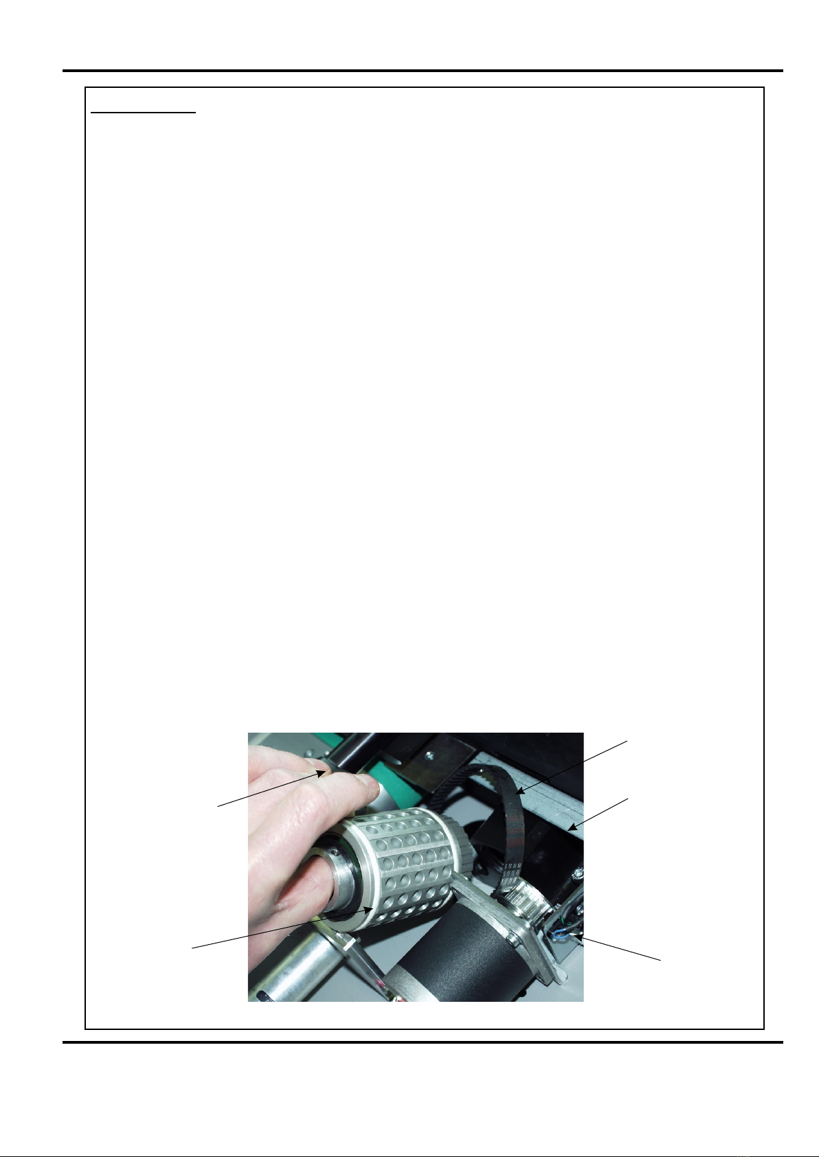
VACUUM DRUM REMOVAL / REPLACEMENT.
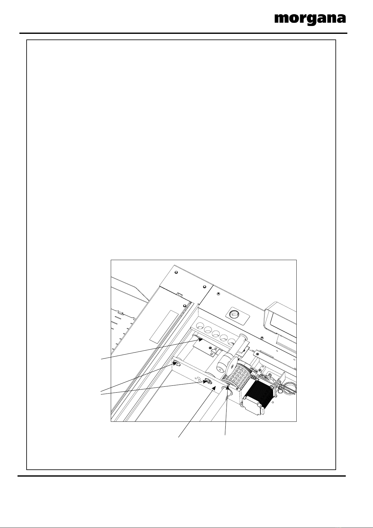
1. Remove the Compressor cover below the feed bed.
2. Remove the top stainless steel feed bed.
3. Remove the moving side guide.
4. From the underside of the fed table loosen the valve assembly by unscrewing
the two M5 posi pan head screws, allow the assembly to hang on its two pipes.
5. Inside the feed table to the rear, locate the two M4 soc cap head screws that 'position’
the black delrin housing in place, this is the support block for the drum and the choke.
6. Using a 4mm A/F ball ended allen key loosen the two screws until they are flush with
the underside of the mounting block, this will enable the delrin block to slide to the rear
of the machine.
7. Locate the M4 soc set screw in the bearing plate that is used to lock the choke tube to
the choke and using a 3mm A/F allen key unscrew until clear of the plate.
8. Twist the vacuum drum towards the motor to clear the bearing plate location hole and
withdraw the drum assembly clear of the machine.
Replacing the Vacuum Drum assembly.
Replacement is the reverse procedure.
1. Place the delrin block loosely in position .
2. Ensuring the end plug is correctly located in the end of choke tube the vacuum drum
can be manoeuvred into position, ensure the wavey washer is correctly positioned
between the drum and the bearing plate.
3. Ensure the drive belt is in place and thew 'O'ring is in the lock, slide the delrin bloc
k over the choke tube end. Using the 4mm A/F ball ended allen key tighten the two
locating screws into the feed table clearance holes.
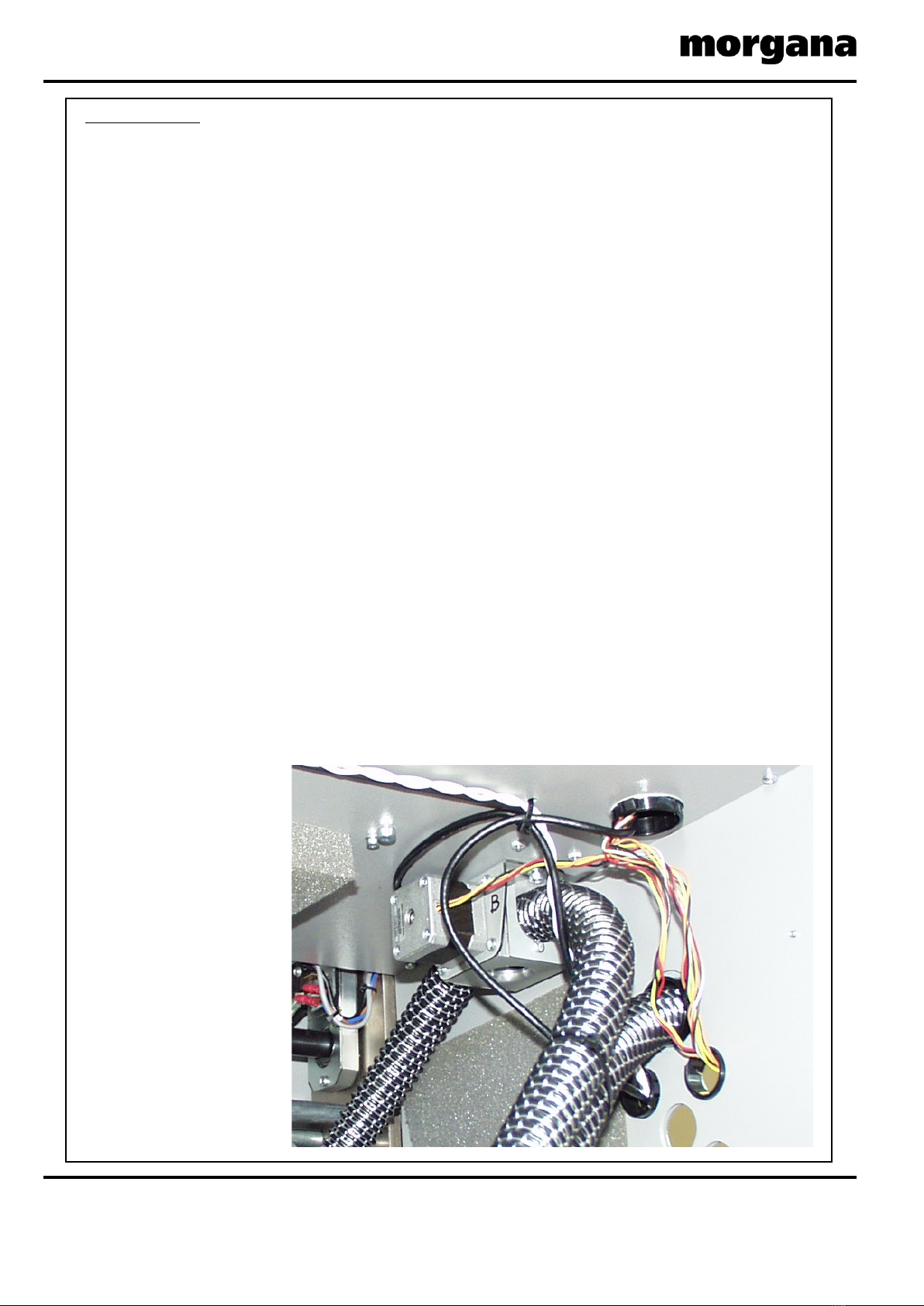
4. Refit the vlave assembly beneath the feed table ensuring the 'O' ring is correctly
located and the two M5 posi pan head screws are tight.
5. The feed bed and compressor cover can then be refitted.
Vacuum Drum
Mounting Block
Papergate
Assembly
Sensor
Vacuum
Drum
Timing
Belt
FIG.2.1

Page 8 CREASING
VACUUM DRUM FEED BELT REMOVAL / REPLACEMENT.
Drum Drive Belt replacement.
1. Following stages 1 to 6 above, the belt can be removed from the vacuum drum.
2. Remove the slot sensor from the motor mounting bracket.
3. The belt can now be removed from the machine.
Replacement is the reverse procedure.
To tension the belt loosen the three screws fixing the bracket to the feed table,
adjust the tension to allow a quarter of a twist along its run and retighten the cap head screws.
Replacing the drive motor or sensor.
1. Remove the Compressor cover below the feed bed and the rear cover
2. Remove the top stainless steel feed bed.
3. Remove the moving side guide.
4. Unplug the motor or the sensor from the respective PCB at the rear of the machine
and feed the wire up through the access holes.
5. Unscrew the motor or the sensor from the motor mounting bracket and remove.
Replacement is the reverse procedure.
To tension the belt loosen the three screws fixing the bracket to the feed table,
adjust the tension to allow a quarter of a twist along its run and retighten the cap head screws.
Note. care should be taken not to over tighten the slot sensor as it is plastic.
FIG.2.2
M5 Socket
Screw
Bearings
and Shims
Center
Support
Plate
Feed Belt

SYSTEM
AutoCreaser Pro 50
Page 9
BLANK
PAGE

Page 10 CREASING
SECTION 3
Removal of Butterfly Valve Assembly.
The Butterfly Valve assembly is located on the underside of the feed bed, towards the
back of the machine.
3.1 Remove the two pipe mounting clip plates (ITEM 5 on page 11) so that the hoses can
be detached from the valve.
3.2 Remove the two screws that secure the valve to the underside of the feed bed.
NOTE.
When refitting the valve ensure that the ends of the hoses are clear of nylon fibres and that
the ‘O’ ring is in place.

SYSTEM
AutoCreaser Pro 50
Page 11
4 Posns.
11
2 Posns.
13
4
9
8
7
2
10
14
2 Posns.
11
2 Posns.
5
6
4 Posns.
12
3
1
Magnet Polarity
Orientation
is IMPORTANT.
Sensor Orientation Nylon Grub Screw
(ITEM 14)
Flat Face of Sensor
2. Magnet Polarity Orientation is IMPORTANT.
1. Items 7 Should Be Secured Into Item 4 using a
Suitable High Strength Adhesive.
NOTES.
BUTTERFLY VALVE ASSEMBLY (175-28-01)
ITEM NO. PART NUMBER QTY. Description
11
2175-164-01 Valve Block Tube - Stepper
3
173-65-01
1
Valve Motor & Lead Assembly
175-176-01
1
4
2Pipe Mounting Clip
5
175-166-01 Solid Butterfly
1
6
401-02-040-008
Dowel Pin Ø3 x 12 Lg.
7601-168 2
81
602-178
175-177-01 Upper Valve Spacer
91
1
10
11
12
603-108
6Screw - Pan Pozi Taptite - M4 x 8 Lg.
404-01-030-008 4Screw - Socket Countersunk Hd - M3 x 8 Lg.
13
173-67-01
409-01-030-008 2Screw - Skt set - Flat Pt. - M3 x 8 Lg.
175-165-01
1
Valve Mounting Plate
Magnet - Ø3 x 3 Long
Bearing - Iglidur Plain Ø3 X Ø5 x 4 Lg.
Lead - Valve Sensor
14 416-01-060-008 1Grub Screw - Slotted Nylon M6 x 8 Lg.

Page 12 CREASING
BLANK
PAGE

SYSTEM
AutoCreaser Pro 50
SECTION 4
MAIN CREASER MECHANISM
REMOVAL OF UNIT
4.1 First access should be gained by removing the top infeed and outfeed guards
(See Section 1)
4.2 Detach guard micro switch by removing two screws, taking care not to drop them.
4.3 Cut and remove cable ties from cable mounting, retaining wiring loom.
Ensure that the mains is unplugged.
4.4 From the rear of the machine, remove two button socket screws with their
washers.
4.5 Remove the ’unlock’ knob from the front of the machine.
4.6 Remove the polycord drive belt from the suction drum.
4.7 The unit can be lifted by two people vertically out of the main frame with care.
One person should be guiding the wiring and plugs to ensure they do not get
trapped during the lifting.
Page 13

Page 14 CREASING
4.8 Place the unit on a solid and clear bench ensuring no wires are trapped beneath
the metal side plates.
4.9 Assemble loosely the green drive belt to the pulley
4.10 Replace the unit ensuring the wiring harness is threaded as it was removed
4.11 Attach the belt to the drive shaft.
4.12 Fit the tilt lever to the inside front frame with the bottom button head and screw
in tilt knob.
4.13 Slide rear spacer bar down in position (see below). Fix the bottom screw in and
align the top screw and fit loosely. Replace cable ties to mountings. Align the
roller set square with the fixed lay edge while the front tilt lever is in the centre
position. (Use the rear slots to adjust square) Tighten the screws and replace
the top covers.

SYSTEM
AutoCreaser Pro 50
SECTION 5
REMOVAL/REPLACEMENT STEPPER DRIVE BELT/
PULLEYS
5.1 Loosen the adjuster nut from the inside unit and slide the belt off.
5.2 Loosen the securing socket set screws in the drive pulley on the roller for it
to be removed (NOTE there is one screw located in a hole in the shaft)
5.3 Refitting the belt is a reverse procedure. To tighten the belt, first adjust the drive
motor down to allow ‘feel’ of belt tightness; then re-adjust the motor / gear mesh
to allow minimum backlash.
Page 15

Page 16 CREASING
SECTION 6
REMOVAL/REPLACEMENT OF TOP INFEED ROLLLER
6.1 With the unit on a bench
6.2 Remove the drive belt and flanged pulley from the bottom infeed roller.
6.3 Viewing on the outside of the sideplate, align the lug on the eccentric
with cutout in the sideplate.
6.4 Using a soft mallet gently tap the roller assembly from the opposite
side supporting its length as it emerges.
REMOVAL/REPLACEMENT OF BOTTOM INFEED ROLLLER
6.5 Remove the drive belt and top infeed roller assembly and the bottom
flanged pulley as above.
6.6 Remove the cap head screw from the rear of the roller shaft, and then remove the
pulley.
6.7 Gently tap the roller from the rear, this will extract the outer race of the needle
bearing from the front side plate.
6.8 The roller can now be withdrawn inwards through the mechanism.
6.9 Remove the bearing retaining screw on the inside of the rear side plate, the deep
grooved ball race can now be extracted.

SYSTEM
SECTION 7
DRIVE HUB: REPLACE RUBBER TORSION BUSH (SHOCK
ABSORBER).
7.1 Loosen grub screws in one half of hub.
7.2 Slide hub outward & remove rubber torsion bush.
7.3 Replace in reverse order.
Rubber Torsion Bush
Page 17
AutoCreaser Pro 50

Page 18 CREASING
Micro Switch Assembly Link Plate
SECTION 8
DRIVE LINK REFURBISHMENT
8.1 Remove the drip tray by removing the four securing screws fixed to the tie bars.
8.2 Remove both tie bars and drip tray.
8.3 Remove the micro switch assembly to gain access to the rear drive link.
8.4 Using a short dumpy posi drive screwdriver, unscrew the three screws from the side
of the link plate. Slide the side off (‘O’ Rings should be maintained in position).
The plastic drive link can be removed by sliding it forward.
8.5 Replace the drive link and outer plate.
8.6 Re-assemble in reverse order.

SYSTEM Page 19
AutoCreaser Pro 50
SECTION 9
ELECTRICS: The PRO Control System.
The Morgana PRO control system is essentially a computer system just like the PC you
use at home. Unlike your Microsoft Windows PC, the PRO system uses a LINUX operating
system and runs only one program, which is the machine control program for the particular
machine that it is installed on.
Block Diagram of the PRO
Control
System
ITX
Motherboard
Controller
PCB
ATX PSU
E-Stop
240V AC
5V DC / 12V DC / 0V
RED/ YELLOW / BLACK
<- Comms ->
GUI
USB Stick / Flash
Drive
(Hard Drive)
Touch Panel
VGA
Digital<>Analogue
Interface PCB
Machine Control
Processor PCB
Touchscreen
Display
115V AC
Transformer
Assembly

Page 20 CREASING
SECTION 9
ELECTRICS: REMOVAL/REFITTING PCB/POWER SUPPLY ASSEMBLY
All the Electric controls and pcbs are located within the rear cover mounted on a common
base plate.
REPLACEMENT OF MAIN CONTROL P.C.B.
This PCB controls all functions of the machine and houses the Main Program PCB.
The use of an antistatic wrist band should be used during work on the main control PCB.
Switch the mains power off and disconnect from the mains supply.
Unplug all the green plugs from the PCB.
Using a posi-drive screw driver, unscrew the five fixing screws and carefully remove the PCB.
NOTE.
When fitting a new board it is important that the switch, SW1, must be set in the correct
position. For machines with Serial No. 730419 or higher the switch must be set over to the left
in the AUTO EDGE position; these machines were fitted with Lead Edge Auto Sensing as
standard. For machines with Serial numbers earlier than 730419 the switch must generally be
set over to the right in the POT EDGE position, unless the machine has been upgraded to
include Lead Edge Auto Sensing. Earlier Machines that have been upgraded with Lead
Edge Auto Sensing will have a main processor revision of A1.3x1 or higher and a
touchscreen software revision of AC5.0x3 or higher; for these machines the switch must be set
over to the left in the AUTO EDGE position. See technical bulletin TB2744 Iss.B. for further
information.
SWITCH (SW1)
Table of contents