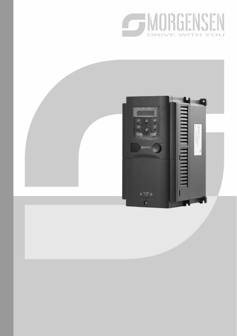
Morgensen MSI350 Series User manual

MSI350 SERIES
INVERTER
USER
MANUAL

2

3
Preface
Thank you for choosing MSI350 series inverter.
MSI350 is a high-performance and multipurpose inverter aiming to integrate synchronous motor
drive with asynchronous motor drive, and torque control, speed control with position control. It
is armed with advanced vector control technology and the latest digital processor dedicated for
motor control, thus enhancing product reliability and adaptability to the environment. MSI350
series inverter adopts customized and industrialized design to realize excellent control
performance through optimized functions and flexible applications.
In order to meet diversified customer demands, MSI350 series inverter provides abundant
extension cards including programmable extension card, PG card, communication card and I/O
extension card to achieve various functions as needed.
The programmable extension card adopts the mainstream development environment for
customers to carry out secondary development easily, fulfilling varied customized needs and
reducing customer cost.
PG card supports a variety of encoders like incremental encoders and resolver-type encoders,
in addition, it also supports pulse reference and frequency-division output. PG card adopts
digital filter technology to improve EMC performance and to realize stable transmission of the
encoder signal over a long distance. It is equipped with encoder offline detection function to
contain the impact of system faults.
MSI350 series inverter supports multiple kinds of popular communication modes to realize
complicated system solutions. It can be connected to the internet with optional wireless
communication card, by which users can monitor the inverter state anywhere any time via
mobile APP.
MSI350 series inverter uses high power density design. Some power ranges carry built-in DC
reactor and brake unit to save installation space. Through overall EMC design, it can satisfy the
low noise and low electromagnetic interference requirements to cope with challenging grid,
temperature, humidity and dust conditions, thus greatly improving product reliability.
This operation manual presents installation wiring, parameter setup, fault diagnosis and trouble
shooting, and precautions related to daily maintenance. Read through this manual carefully
before installation to ensure MSI350 series inverter is installed and operated in a proper manner
to give full play to its excellent performance and powerful functions.
Our company reserves the right to update the information of our products.

4
Contains
1. Safety precautions ______________________________________ 13
1.1 What this chapter contains _______________________________ 13
1.2 Safety definition _______________________________________ 13
1.3 Warning symbols ______________________________________ 13
1.4 Safety guidelines ______________________________________ 14
1.4.1 Delivery and installation_____________________________ 15
1.4.2 Commissioning and running _________________________ 16
1.4.3 Maintenance and component replacement ______________ 17
1.4.4 What to do after Scrapping __________________________ 17
2. Quick startup___________________________________________ 18
2.1 What this chapter contains _______________________________ 18
2.2 Unpack inspection _____________________________________ 18
2.4 Application confirmation _________________________________ 19
2.5 Environment confirmation________________________________ 19
2.6 Installation confirmation _________________________________ 19
2.7 Basic commissioning ___________________________________ 20
3. Product overview _______________________________________ 21
3.1 What this chapter contains _______________________________ 21
3.2 Basic principle ________________________________________ 21
3.3 Product specification ___________________________________ 23
3.4 Product nameplate _____________________________________ 25
3.5 Type designation key ___________________________________ 25

5
3.6 Rated value __________________________________________ 26
3.6.1 AC 3PH 380V(-15%)–440V(+10%) rated value___________ 26
3.6.2 AC 3PH 520V (-15%)–690V (+10%) rated value__________ 27
3.7 Structure diagram ______________________________________ 28
4. Installation guide________________________________________ 29
4.1 What this chapter contains _______________________________ 29
4.2 Mechanical installation __________________________________ 29
4.2.1 Installation environment_____________________________ 29
4.2.2 Installation direction________________________________ 30
4.2.3 Installation mode __________________________________ 31
4.2.4 Single-unit installation ______________________________ 32
4.2.5 Multiple-unit installation _____________________________ 32
4.2.6 Vertical installation_________________________________ 34
4.2.7 Tilted installation __________________________________ 35
4.3 Standard wiring of main circuit ____________________________ 36
4.3.1 Wiring diagram of main circuit ________________________ 36
4.3.2 Main circuit terminal diagram_________________________ 37
4.3.3 Wiring process of the main circuit terminals _____________ 42
4.4 Standard wiring of control circuit___________________________ 43
4.4.1 Wiring diagram of basic control circuit__________________ 43
4.4.2 Input/output signal connection diagram_________________ 45
4.5 Wiring protection_______________________________________ 46
4.5.1 Protect the inverter and input power cable in short-circuit___ 46
4.5.2 Protect the motor and motor cable in short circuit _________ 47
4.5.3 Protect motor and prevent thermal overload _____________ 47
4.5.4 Bypass connection ________________________________ 47
5. Basic operation instructions _______________________________ 49

6
5.1 What this chapter contains _______________________________ 49
5.2 Keypad introduction ____________________________________ 49
5.3 Keypad display ________________________________________ 53
5.4 Stop parameter display state _____________________________ 53
5.5 Running parameter display state __________________________ 54
5.6 Fault alarm display state_________________________________ 54
5.7 Keypad operation ______________________________________ 55
5.7.1 Enter/exit menu ___________________________________ 55
5.7.2 List edit _________________________________________ 60
5.7.3 Add parameters to the parameter list displayed in stop/running
state 61
5.7.4 Add parameter to common parameter setup list __________ 62
5.7.5 Parameter selection edit interface _____________________ 62
5.7.6 Parameter setup edit interface _______________________ 63
5.7.7 State monitoring interface ___________________________ 64
5.7.8 Motor parameter autotuning _________________________ 64
5.7.9 Parameter backup _________________________________ 65
5.7.10 System setup ___________________________________ 66
5.7.11 Power-on guiding settings _________________________ 66
5.8 Basic operation instruction _______________________________ 69
5.8.1 What this section contains___________________________ 69
5.8.2 Common commissioning procedures __________________ 70
5.8.3 Vector control_____________________________________ 74
5.8.4 SVPWM control mode ______________________________ 79
5.8.5 Torque control ____________________________________ 89
5.8.6 Motor parameter __________________________________ 94
5.8.7 Start/stop control _________________________________ 100
5.8.8 Frequency setup _________________________________ 105

7
5.8.9 Analog input_____________________________________ 109
5.8.10 Analog output__________________________________ 112
5.8.11 Digital input ___________________________________ 116
5.8.12 Digital output __________________________________ 123
5.8.13 Simple PLC ___________________________________ 128
5.8.14 Multi-step speed running _________________________ 130
5.8.15 PID control ____________________________________ 132
5.8.16 Run at wobbling frequency _______________________ 137
5.8.17 Local encoder input _____________________________ 139
5.8.18 Commissioning procedures for position control and spindle
positioning function _____________________________________ 140
5.8.19 Fault handling _________________________________ 146
6. Function parameter list __________________________________ 151
6.1 What this chapter contains ______________________________ 151
6.2 Function parameter list _________________________________ 151
7. Troubleshooting _______________________________________ 251
7.1 What this chapter contains ______________________________ 251
7.2 Indications of alarms and faults __________________________ 251
7.3 Fault reset___________________________________________ 251
7.4 Fault history _________________________________________ 251
7.5 Inverter faults and solutions _____________________________ 251
7.5.1 Details of faults and solutions _______________________ 252
7.5.2 Other state______________________________________ 259
7.6 Analysis on common faults ______________________________ 260
7.6.1 Motor fails to work ________________________________ 260
7.6.2 Motor vibrates ___________________________________ 261
7.6.3 Overvoltage _____________________________________ 262

8
7.6.4 Undervoltage ____________________________________ 263
7.6.5 Unusual heating of motor __________________________ 264
7.6.6 Inverter overheating_______________________________ 265
7.6.7 Motor stalls during ACC____________________________ 266
7.6.8 Overcurrent _____________________________________ 267
7.7 Countermeasures on common interference _________________ 268
7.7.1 Interference on meter switches and sensors____________ 268
7.7.2 Interference on communication ______________________ 269
7.7.3 Failure to stop and indicator shimmering due to motor cable
coupling _____________________________________________ 270
7.7.4 Leakage current and interference on RCD _____________ 271
7.7.5 Live device chassis _______________________________ 272
8. Maintenance and hardware fault diagnosis __________________ 273
8.1 What this chapter contains ______________________________ 273
8.2 Periodical inspection___________________________________ 273
8.3 Cooling fan __________________________________________ 275
8.4 Capacitor ___________________________________________ 276
8.4.1 Capacitor reforming _______________________________ 276
8.4.2 Electrolitic capacitor replacement ____________________ 278
8.5 Power cable _________________________________________ 278
9. Communication protocol _________________________________ 279
9.1 What this chapter contains ______________________________ 279
9.2 Modbus protocol introduction ____________________________ 279
9.3 Application of Modbus _________________________________ 279
9.3.1 RS485 _________________________________________ 279
9.3.2 RTU mode ______________________________________ 282

9
9.4 RTU command code and communication data_______________ 286
9.4.1 Command code: 03H, reading N words (continuously reading a
maximum of 16 words) __________________________________ 286
9.4.2 Command code: 06H, writing a word _________________ 287
9.4.3 Command code: 08H, diagnosis _____________________ 288
9.4.4 Command code: 10H, continuous writing ______________ 289
9.4.5 Data address definition ____________________________ 290
9.4.6 Fieldbus scale ___________________________________ 294
9.4.7 Error message response ___________________________ 295
9.4.8 Read/Write operation example ______________________ 297
9.5 Common communication faults __________________________ 302
Appendix A Extension cards__________________________________ 303
A.1 Model definition ______________________________________ 303
A.2 Dimensions and installation _____________________________ 309
A.3 Wiring ______________________________________________ 312
A.4 IO extension card function description _____________________ 312
A.4.1 IO extension card––EC-IO501-00 _____________________ 312
A.5 PG extension card function description ____________________ 315
A.5.1 Multi-function incremental PG card––EC-PG505-12_______ 315
A.5.2 UVW incremental PG card––EC-PG503-05 _____________ 319
A.5.3 Resolver PG card––EC-PG504-00 ____________________ 322
A5.4 24 V multi-function incremental PG card——EC-PG505-24 _ 324
A5.5 Sin/Cos PG card——EC-PG502 ______________________ 326
A.6 Communication card function description __________________ 329
A.6.1 Bluetooth communication card––EC-TX501 and WIFI
communication card––EC- TX502 _________________________ 329
A.6.2 CANopen communication card––EC-TX505 and CAN
master/slave control communication card EC- TX511 __________ 332

10
A.6.3 Ethernet communication card––EC-TX504 ______________ 333
A.6.4 PROFIBUS-DP communication card––EC-TX503 ________ 334
A.6.5 PROFINET communication card——EC- TX509 _________ 336
A.7 Programmable extension card function description ___________ 339
A.7.1 Programmable extension card––EC-PC501-00 __________ 339
Appendix B Technical data ___________________________________ 342
B.1 What this chapter contains______________________________ 342
B.2 Derated application ___________________________________ 342
B.2.1 Capacity ________________________________________ 342
B.2.2 Derating_________________________________________ 342
B.3 Grid specifications ____________________________________ 343
B.4 Motor connection data _________________________________ 343
B.4.1 EMC compatibility and motor cable length ______________ 344
B.5 Application standards __________________________________ 344
B.5.1 CE marking ______________________________________ 344
B.5.2 EMC compliance declaration_________________________ 345
B.6 EMC regulations______________________________________ 345
B.6.1 Inverter category of C2 _____________________________ 345
B.6.2 Inverter category of C3 _____________________________ 346
Appendix C Dimension drawings ______________________________ 347
C.1 What this chapter contains______________________________ 347
C.2 Keypad structure _____________________________________ 347
C.2.1 Structure diagram _________________________________ 347
C.2.2 Keypad installation bracket __________________________ 347
C.3 Inverter structure _____________________________________ 348
C.4 Dimensions of Inverters of AC 3PH 380V (-15%)–440V (+10%) _ 349

11
C.4.1 Wall-mounting dimensions __________________________ 349
C.4.2 Flange installation dimensions _______________________ 351
C.4.3 Floor installation dimensions _________________________ 353
C.5 Dimensions of Inverters of AC 3PH 520V (-15%)–690V (+10%) _ 354
C.5.1 Wall-mounting dimensions __________________________ 354
C.5.2 Flange installation dimensions _______________________ 355
C.5.3 Floor installation dimensions _________________________ 356
Appendix D Dimension drawings ______________________________ 358
D.1 What this chapter contains______________________________ 358
D.2 Wiring of peripheral accessories _________________________ 358
D.3 Power supply ________________________________________ 360
D.4 Cables _____________________________________________ 360
D.4.1 Power cables_____________________________________ 360
D.4.2 Control cables ____________________________________ 361
D.4.3 Cable arrangement ________________________________ 365
D.4.4 Insulation inspection _______________________________ 366
D.5 Breaker and electromagnetic contractor ___________________ 366
D.5.1 Breakers and electromagnetic contactors for AC 3PH 380V (-
15%)–440V (+10%) ____________________________________ 367
D.5.2 Breakers and electromagnetic contactors for AC 3PH 520V (-
15%)–690V (+10%) ____________________________________ 367
D.6 Reactors____________________________________________ 368
D.6.1 Reactors for AC 3PH 380V (-15%)–440V (+10%)_________ 369
D.6.2 Reactors for AC 3PH 520V (-15%)–690V (+10%)_________ 370
D.7 Filters ______________________________________________ 372
D.7.1 Filter model description _____________________________ 372
D.7.2 Filters for AC 3PH 380V (-15%)–440V (+10%) ___________ 373

12
D.7.3 Filters for AC 3PH 520V (-15%)–690V (+10%) ___________ 374
D.8 Brake system ________________________________________ 375
D.8.1 Brake component selection__________________________ 375
D.8.2 Brake resistor cable selection ________________________ 379
D.8.3 Brake resistor installation ___________________________ 379
Appendix E STO function description___________________________ 381
E.1 STO function logic table ________________________________ 381
E.2 STO Channel delay description __________________________ 382
E.3 STO function installation checklist ________________________ 382
Appendix F Acronyms and abbreviations ________________________ 383
Appendix G Further information _______________________________ 385
G.1 Product and service queries ____________________________ 385
G.2 Feedback on MORGENSEN inverter manuals ______________ 385
G.3 Documents on the internet______________________________ 385

13
1. Safety precautions
1.1 What this chapter contains
Read this manual carefully and follow all safety precautions before moving, installing, operating and
servicing the inverter. If these safety precautions are ignored, physical injury or death may occur, or
damage may occur to the equipment.
If any physical injury or death or damage to the equipment occur due to neglect of the safety
precautions in the manual, our company will not be responsible for any damages and we are not legally
bound in any manner.
1.2 Safety definition
Danger: Serious physical injury or even death may occur if related requirements are not followed
Warning: Physical injury or damage to the equipment may occur if related requirements are not
followed
Note: Procedures taken to ensure proper operation.
Qualified electricians: People working on the device should take part in professional electrical and
safety training, receive the certification and be familiar with all steps and requirements of installing,
commissioning, operating and maintaining the device to prevent any emergencies.
1.3 Warning symbols
Warnings caution you about conditions which can result in serious injury or death and/or damage to
the equipment, and advice on how to avoid the danger. Following warning symbols are used in this
manual.
Symbols Name Instruction Abbreviation
Danger Danger
Serious physical injury or even death
may occur if related requirements are
not followed
Warning Warning
Physical injury or damage to the
equipment may occur if related
requirements are not followed
Forbid
Electrostatic
discharge
Damage to the PCBA board may occur
if related requirements are not followed
Hot Hot sides The base of the inverter may become
hot. Do not touch.

14
Symbols Name Instruction Abbreviation
Electric
shock
As high voltage still presents in the bus
capacitor after power off, wait for at
least five minutes (or 15 min / 25 min,
depending on the warning symbols on
the machine) after power off to prevent
electric shock
Read
manual
Read the operation manual before
operating on the equipment
Note Note Procedures taken to ensure proper
operation Note
1.4 Safety guidelines
Only trained and qualified electricians are allowed to carry out related
operations.
Do not perform wiring, inspection or component replacement when power supply
is applied. Ensure all the input power supplies are disconnected before wiring
and inspection, and wait for at least the time designated on the inverter or until
the DC bus voltage is less than 36V. The minimum waiting time is listed in the
table below.
Inverter model Minimum waiting time
380V 1.5kW-110kW 5 min
380V 132kW-315kW 15 min
380V Above 355kW 25 min
660V 22kW-132kW 5 min
660V 160kW-350kW 15 min
660V 400kW-630kW 25 min
Do not refit the inverter unless authorized; otherwise, fire, electric shock or other injuries
may occur.
The base of the radiator may become hot during running. Do not touch to avoid hurt.
The electrical parts and components inside the inverter are electrostatic. Take measures
to prevent electrostatic discharge during related operation.

15
1.4.1 Delivery and installation
Install the inverter on fire-retardant material and keep the inverter away from
combustible materials.
Connect the optional brake parts (brake resistors, brake units or feedback units)
according to the wiring diagram.
Do not operate on a damaged or incomplete inverter.
Do not touch the inverter with wet items or body parts; otherwise, electric shock
may occur.
Note:
Select appropriate tools for delivery and installation to ensure a safe and proper running of the
inverter and avoid physical injury or death. To ensure physical safety, the installation staff
should take mechanical protective measures like wearing exposure shoes and working
uniforms;
Ensure to avoid physical shock or vibration during delivery and installation;
Do not carry the inverter by its front cover only as the cover may fall off;
Installation site should be away from children and other public places;
The inverter cannot meet the requirements of low voltage protection in IEC61800-5-1 if the
altitude of installation site is above 2000m;
The inverter should be used in proper environment (see chapter 4.2.1 Installation environment
for details);
Prevent the screws, cables and other conductive parts from falling into the inverter;
As leakage current of the inverter during running may exceed 3.5mA, ground properly and
ensure the grounding resistance is less than 10Ω. The conductivity of PE grounding conductor
is the same with that of the phase conductor (with the same cross sectional area).
R, S and T are the power input terminals, and U, V and W are output motor terminals. Connect
the input power cables and motor cables properly; otherwise, damage to the inverter may
occur.

16
1.4.2 Commissioning and running
Disconnect all power sources applied to the inverter before terminal wiring, and
wait for at least the time designated on the inverter after disconnecting the power
sources.
High voltage presents inside the inverter during running. Do not carry out any
operation on the inverter during running except for keypad setup. For products at
voltage levels of 5 or 6, the control terminals form extra-low voltage circuits.
Therefore, you need to prevent the control terminals from connecting to accessible
terminals of other devices.
The inverter may start up by itself when P01.21 (restart after power down) is set to
1. Do not get close to the inverter and motor.
The inverter cannot be used as "Emergency-stop device".
The inverter cannot act as an emergency brake for the motor; it is a must to install
mechanical brake device.
During driving permanent magnet synchronous motor, besides above-mentioned
items, the following work must be done before installation and maintenance.
1. Disconnect all the input power sources including main power and control
power.
2. Ensure the permanent-magnet synchronous motor has been stopped, and
the voltage on output end of the inverter is lower than 36V.
3. After the permanent-magnet synchronous motor is stopped, wait for at least
the time designated on the inverter, and ensure the voltage between "+" and
"-" is lower than 36V.
4. During operation, it is a must to ensure the permanent-magnet synchronous
motor cannot run again by the action of external load; it is recommended to
install effective external brake device or disconnect the direct electrical
connection between permanent-magnet synchronous motor and the inverter.
Note:
Do not switch on or switch off input power sources of the inverter frequently;
For inverters that have been stored for a long time, set the capacitance and carry out
inspection and pilot run on the inverter before use.
Close the front cover before running; otherwise, electric shock may occur.

17
1.4.3 Maintenance and component replacement
Only well-trained and qualified professionals are allowed to perform
maintenance, inspection, and component replacement on the inverter.
Disconnect all the power sources applied to the inverter before terminal
wiring, and wait for at least the time designated on the inverter after
disconnecting the power sources.
Take measures to prevent screws, cables and other conductive matters from
falling into the inverter during maintenance and component replacement.
Note:
Use proper torque to tighten the screws.
Keep the inverter and its parts and components away from combustible materials during
maintenance and component replacement.
Do not carry out insulation voltage-endurance test on the inverter, or measure the control
circuits of the inverter with megameter.
Take proper anti-static measures on the inverter and its internal parts during maintenance and
component replacement.
1.4.4 What to do after Scrapping
The heavy metals inside the inverter should be treated as industrial effluent.
When the life cycle ends, the product should enter the recycling system.
Dispose of it separately at an appropriate collection point instead of placing it
in the normal waste stream.

18
2. Quick startup
2.1 What this chapter contains
This chapter introduces the basic principles required during installation commissioning. Users can
realize quick installation commissioning by following these principles.
2.2 Unpack inspection
Check as follows after receiving products.
1. Check whether the packing box is damaged or dampened. If yes, contact local dealers or
MORGENSEN offices.
2. Check the model identifier on the exterior surface of the packing box is consistent with the
purchased model. If no, contact local dealers or MORGENSEN offices.
3. Check whether the interior surface of packing box is improper, for example, in wet condition,
or whether the enclosure of the inverter is damaged or cracked. If yes, contact local dealers
or MORGENSEN offices.
4. Check whether the nameplate of the inverter is consistent with the model identifier on the
exterior surface of the packing box. If not, contact local dealers or MORGENSEN offices.
5. Check whether the accessories (including user's manual, control keypad and extension card
units) inside the packing box are complete. If not, contact local dealers or MORGENSEN
offices.

19
2.4 Application confirmation
Check the following items before operating on the inverter.
Verify the load mechanical type to be driven by the inverter, and check whether overload
occurred to the inverter during actual application, or whether the inverter power class needs
to be enlarged?
Check whether the actual running current of load motor is less than rated inverter current.
Check whether the control precision required by actual load is the same with the control
precision provided by the inverter.
Check whether the grid voltage is consistent with rated inverter voltage.
Check whether the functions required need an optional extension card to be realized.
2.5 Environment confirmation
Check the following items before use.
1. Check whether the ambient temperature of the inverter during actual application exceeds 40°C,
if yes, derate 1% for every additional 1°C. In addition, do not use the inverter when the ambient
temperature exceeds 50°C.
Note: For cabinet-type inverter, its ambient temperature is the air temperature inside the cabinet.
2. Check whether ambient temperature of the inverter during actual application is below -10°C, if
yes, install heating facility.
Note: For cabinet-type inverter, its ambient temperature is the air temperature inside the cabinet.
3. Check whether the altitude of the application site exceeds 1000m, if yes, derate 1% for every
additional 100 m.
4. Check whether the humidity of application site exceeds 90%, if yes, check whether condensation
occurred, if condensation does exist, take additional protective measures.
5. Check whether there is direct sunlight or animal intrusion in the application site, if yes, take
additional protective measures.
6. Check whether there is dust, explosive or combustible gases in the application site, if yes, take
additional protective measures.
2.6 Installation confirmation
After the inverter is installed properly, check the installation condition of the inverter.
1. Check whether the input power cable and current-carrying capacity of the motor cable fulfill
actual load requirements.
2. Check whether peripheral accessories (including input reactors, input filters, output reactors,
output filters, DC reactors, brake units and brake resistors) of the inverter are of correct type and
installed properly; check whether the installation cables fulfill requirements on current-carrying

20
capacity.
3. Check whether the inverter is installed on fire-retardant materials; check whether the hot parts
(reactors, brake resistors, etc.) are kept away from combustible materials.
4. Check whether all the control cables are routed separately with power cables based on EMC
requirement.
5. Check whether all the grounding systems are grounded properly according to inverter
requirements.
6. Check whether installation spacing of the inverter complies with the requirements in operation
manual.
7. Check whether installation mode of the inverter complies with the requirements in operation
manual. Vertical installation should be adopted whenever possible.
8. Check whether external connecting terminals of the inverter are firm and tight enough, and
whether the moment is up to the requirement.
9. Check whether there are redundant screws, cables or other conductive objects inside the
inverter, if yes, take them out.
2.7 Basic commissioning
Carry out basic commissioning according to the following procedures before operating on the inverter.
1. Select motor type, set motor parameters and select inverter control mode according to actual
motor parameters.
2. Whether autotuning is needed? If possible, disconnect the motor load to carry out dynamic
parameter autotuning; if the load cannot be disconnected, perform static autotuning.
3. Adjust the acceleration and deceleration time based on actual working conditions of the load.
4. Jogging to carry out device commissioning. Check whether the motor running direction is
consistent with the direction required, if no, it is recommended to change the motor running
direction by exchanging the motor wiring of any two phases.
5. Set all the control parameters, and carry out actual operation.
This manual suits for next models
50
Other Morgensen Inverter manuals
Popular Inverter manuals by other brands

Hoymiles
Hoymiles HYS-3.0LV-EUG1 Quick installation guide

Senci
Senci SC13000 Safety instructions & operator's manual

Siemens
Siemens MICROMASTER 411 operating instructions

Badger Power Electronics
Badger Power Electronics BPE-HI-3.6K user manual

Lenze
Lenze i700 Series Mounting instructions

Mastervolt
Mastervolt Whisper 6 user manual