Morita veraviewepocs 2d User manual

2022-02-21 Pub. No.: X7C0-91001-503 (EN) Printed in Japan

Table of Contents
Prevent Accidents.....................................................................................................................................1
For Safe Operation................................................................................................................................... 3
Parts Identification ..................................................................................................................................6
(I) Parts Identification......................................................................................................................................... 6
(II) Patient Frame and Arm Operation Panels...................................................................................................... 9
(III) Parts of Device............................................................................................................................................. 13
(IV) Patient Positioning Tools and Consumable Parts......................................................................................... 13
Operation ................................................................................................................................................14
(I) Preliminary Procedures................................................................................................................................ 15
(II) Operation Procedures................................................................................................................................... 17
Safety Check ...........................................................................................................................................................17
Panorama Exposures .............................................................................................................................................18
(1) Turn Main Switch On..................................................................................................................................18
Emergency Stop Switch .......................................................................................................................................18
(2) Cassette Insertion ........................................................................................................................................19
(3) Panorama Settings.......................................................................................................................................22
(3)-1.Auto Exposure (Digital Direct Auto Exposure) ..........................................................................................22
(3)-2.Manual Exposure ........................................................................................................................................23
(3)-3.No X-ray Setting .........................................................................................................................................23
(3)-4.Partial Panorama .........................................................................................................................................24
(4) Patient Positioning ......................................................................................................................................25
(5) Panorama Exposures ...................................................................................................................................36
(6) Patient Egress and Image Transmission......................................................................................................38
(7) Exposure Regions .......................................................................................................................................41
(7)-1.Panorama.....................................................................................................................................................41
(7)-2.Maxillary Sinus (posterior) (Mag.: 1.5×, throughout).......................................................................................43
(7)-3.TMJ Quadruple (Mag.: 1.3× , throughout)..................................................................................................45
(8) Removing the Digital Cassette....................................................................................................................51
Cephalo Exposures (option) ..................................................................................................................................52
(1) Turn Main switch On ..................................................................................................................................52
Emergency Stop Switch .......................................................................................................................................53
(2) Cassette Insertion ........................................................................................................................................54
(3) LA (Lateral) Exposure.................................................................................................................................56
(4) Patient Positioning ......................................................................................................................................57
(5) X-ray emission ............................................................................................................................................61
(6) Patient Egress and Image Transmission ......................................................................................................63
(7) PA (posteroanterior) Exposure ....................................................................................................................65
(8) Removing the Digital Cassette....................................................................................................................68
Calibrating Digital Cephalo Data for Software Analysis............................................................................................69
(III) After Use...................................................................................................................................................... 70
Turn Main switch Off...........................................................................................................................................70

Maintenance, Parts Replacements, and Storage .................................................................................71
(I) Regular Maintenance....................................................................................................................................71
(II) Replacement Parts ........................................................................................................................................71
(III) Storage..........................................................................................................................................................71
Regular Inspection .................................................................................................................................72
Service Life, Consumables, and Replacement Parts...........................................................................75
Trouble shooting.....................................................................................................................................77
DDAE Verification Procedure...............................................................................................................87
Technical Specifications.........................................................................................................................92
(I) Specifications ...............................................................................................................................................92
(II) Symbols and Markings ...............................................................................................................................104
Electromagnetic Disturbances (EMD) ...............................................................................................108
This manual covers a fully equipped model; refer to the sections covering the instruments
and functions of your own unit.
Thank you for purchasing the Veraviewepocs 2D.
For optimum performance and safety, read this manual thoroughly before using the equipment.
Pay special attention to the cautionary warnings and safety statements.
Keep this manual in a handy place for ready reference.
Trademarks (™) and Registered Trademarks (®):
The names of companies, products, services, etc. used in this manual are either trademarks or registered
trademarks owned by each company.
© 2007 J. MORITA MFG. CORP.


1
Prevent Accidents
ATTENTION CUSTOMERS
Do not fail to receive clear instructions concerning the various ways to use this
equipment as described in this accompanying Manual.
Fill out and sign the warranty and give the dealer from whom you purchased the
equipment his copy.
ATTENTION DEALERS
Do not fail to give clear instructions concerning the various ways to use this equipment
as described in this accompanying Manual.
After instructing the customer in the operation of the equipment, have him fill out and
sign the warranty. Then fill in your own section of the warranty and give the customer
his copy. Do not fail to send the manufacturer’s copy to J. MORITA MFG. CORP.
SAFETY INSTRUCTIONS AND RECORDING INFORMATION
When the Veraviewepocs 2D is installed, the installer or other responsible party must explain the precautions and usages
in the Instructions for Use to the user and the person responsible for maintenance and management.
In accordance with the laws of the relevant country or region, information such as the installation date, explained contents,
the name of operator and healthcare facility’s maintenance representative, and the name of the installer or other
responsible party, may need to be recorded.
PREVENT ACCIDENTS
Most operation and maintenance problems result from insufficient attention being paid to basic safety precautions
and not being able to foresee the possibilities of accidents. Problems and accidents are best avoided by foreseeing
the possibility of danger and operating the unit in accordance with the manufacturer’s recommendations. First
thoroughly read all precautions and instructions pertaining to safety and accident prevention; then, operate the
equipment with the utmost caution to prevent either damaging the equipment itself or causing bodily injury.
Note the meaning of the following symbols and expressions:
This warns the user of danger of death, serious bodily injury or total instrument
damage and failure or fire.
This alerts the user to the risk of light to medium injury or instrument damage.
This alerts the user of important points concerning operation.
The user (e.g., healthcare facility, clinic, hospital etc.) is responsible for the management, maintenance and use of
medical devices.
Disregarding the information on safety is considered ABNORMAL USE.
Do not use this equipment for anything other than its specified dental treatment purpose.
Caution: Federal law restricts this device to sale by or on the order of a dentist (Valid only for U.S.A.)

2
INTENDED OPERATOR PROFILE
a) Qualification:
Legally qualified person such as radiologic technician and dentists for X-ray device operation (it may
differ among countries).
b) Education and Knowledge:
It is assumed that the user understands the risks of X-rays and the protective steps required. It is also
assumed that the user is thoroughly familiar with X-ray diagnosis, anatomy, and hygiene including the
prevention of cross contamination.
c) Language Understanding:
English (Intended for professional use as described above.)
d) Experience:
Experienced person with operating X-ray devices.
No special training is required except in cases where this is required by legal regulations of the relevant
country or region.
RELATED DOCUMENTS
• Installation Instructions
ATTENTION
• J. MORITA MFG. CORP. will not be responsible for accidents, instrument damage, or bodily
injury resulting from:
(1) Repairs made by personnel not authorized by J. MORITA MFG. CORP.
(2) Any changes, modifications, or alterations of its products.
(3) The use of products or instrument made by other manufacturers, except for those
procured by J. MORITA MFG. CORP.
(4) Maintenance or repairs using parts or components other than those specified by J.
MORITA MFG. CORP. and other than in their original condition.
(5) Operating the instrument in ways other than the operating procedures described in this
manual or resulting from the safety precautions and warnings in this manual not being
observed.
(6) Workplace conditions and environment or installation conditions which do not conform to
those stated in this manual such as improper electrical power supply.
(7) Fires, earthquakes, floods, lightning, natural disasters, or acts of God.
• The useful life of the Veraviewepocs 2D is 10 years from the date of installation provided it is
regularly and properly inspected and maintained.
• J. MORITA MFG. CORP. will supply replacement parts and be able to repair the product for a
period of 10 years after the manufacture of the product has been discontinued.

3
For Safe Operation
•Do not use the wireless transmission devices listed below in the examination area:
1. Mobile terminals and smart devices.
2. Wireless transmitting devices such as ham radios, walkie-talkies, and transceivers.
3. Personal Handy-phone System (PHS)
4. Routers for intra-building paging systems, wireless LAN, cordless analogue telephones, and
other electric wireless devices.
•Interference from the Veraviewepocs 2D, devices listed below might malfunction or operate in a
random, unexpected and dangerous manner.
1. Electrical diagnostic, examination or treatment devices.
2. Personal computers
•The Veraviewepocs must be installed in an X-ray shield location. Local regulation for radiation
protection must be observed.
•The control box and emission button must be installed
in a radiation protected area.
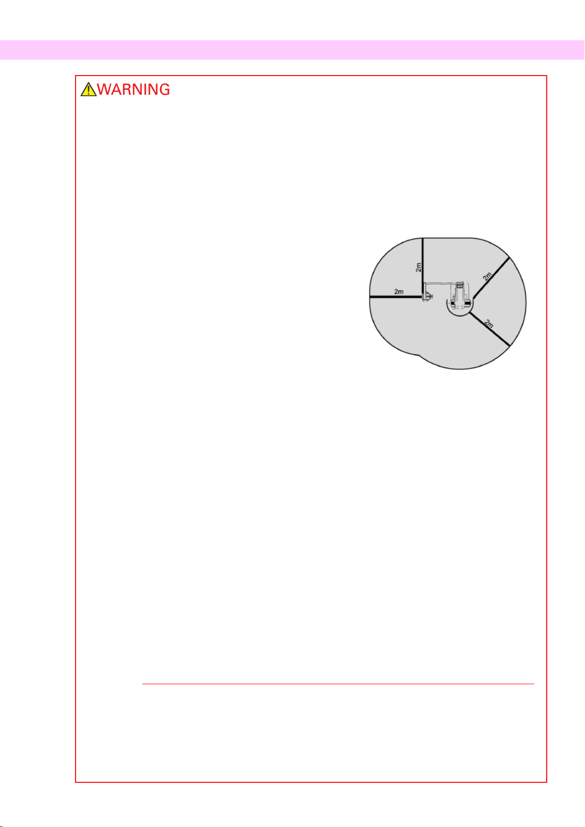
•If the Veraviewepocs is not enclosed by an X-ray booth
or other protective barrier, everyone except the patient
must stay outside the area shown in the illustration
during X-ray emission.
The X-ray protection area should consist of a wall, floor
and ceiling with a minimum of 1.5 mm lead shielding or
its equivalent and should have glass windows with a
minimum of 1.5 mm lead shielding or its equivalent,
through which the operator can observe the patient. A
sign should clearly identify the area as an X-ray
protection area, and a caution sign should light up
during X-ray emission. Observe local regulations.
•The user must restrict access to the equipment in accordance with local regulations for radiation
protection.
•The patient and operator must be provided with appropriate X-ray protection gear such as
lead-impregnated clothing that conforms to local regulations.
•Proper infection control procedures must be established and maintained for each patient.
•It is strongly suggested that no unauthorized personnel be in the immediate area when the
equipment is in use.
•This unit is not designed for and must not be used for “fluoroscopic examinations”.
•Proper radiation safety precautions must be established in accordance with local, state and
governmental regulations in regards to operator and patient protection. The ultimate responsibility
lies with the owner/operator to ensure that the protection requirements of national and local codes
are met.
•When an examination requires X-ray irradiation to implantable or wearable electronic medical
device, the operator must take proper care after referring to the operation manual (and related
safety information) for such implantable or wearable electronic medical devices because if a
diagnostic X-ray device directly irradiates an implantable or wearable electronic medical device, it
can cause sufficient electronic interference to affect the function and operation of the medical
device.
*For reference, U.S.A. FDA published about interference with cardiac implantable electronic
devices (pacemakers and implantable cardioverter defibrillators), insulin pumps, and
neurostimulators on the following web site. (Accessed July 2018)
Title: Interference between CT and Electronic Medical Devices
URL: https://www.fda.gov/Radiation-EmittingProducts/RadiationSafety/ElectromagneticCompatibilityEMC/ucm489704.htm
•Judgement and caution should be used in regards to radiographs of pregnant women. The
decision should be based on “clinical need of diagnostic information”.
•The operator must be able to see the exposure emissions lights and hear the audible signal
during operation of the equipment.
•The operator must be able to see and hear the patient during the operation of the equipment.
•Responsible organization in medical institution needs for providing means for audio and visual
communication between the operator and the patient.

4
•Watch the area around the moving parts to avoid collision against the body parts or other objects
which may result in injury.
•The EQUIPMENT should not be used adjacent to or stacked with other equipment and that if adjacent
or stacked use is necessary, the EQUIPMENT should be observed to verify normal operation in the
configuration in which it will be used.
•Do not fail to turn the unit off after use; this will eliminate the risk of electrical leakage and accidents.
•The main switch should be turned off during standard maintenance procedures. It is also
recommended that the main breaker or fuse on the main electrical distribution panel be turned off as
some electricity reaches the main power terminal inside the unit even when the main switch is off.
•Do not use this equipment for patients when it is being maintained or serviced.
•Use special care to explain to the patient proper instructions as to when they can move as there are
“multiple movements” with certain exposures.
•Do not press the panel too hard not to damage the panel.
•Make sufficient space around the Main Switch so that it is easily accessible in case of emergency.
•Make sufficient space around the power plug so that it is easily unplugged in case of emergency.
(For EX-1)
•Make sufficient space around the power distribution panel so that it is easily to open the breaker in
case of emergency. (For EX-2)
•To avoid the risk of electric shock, this equipment must only be connected to the supply mains with
protective earth.
•Do not use multiple portable socket outlet nor extension cord for the system power supply.
•Do not touch simultaneously the patient and the conductive parts, such as the connector terminals.

5
•Always try to maintain contact with the patient visually and auditorily to ensure safe operation of the
unit.

6
Parts Identification
(I) Parts Identification
Main Unit
Base
Support Column
Lift
Cephalo Unit (Option)
Operation Panel
Arm
Mirror
Chin Rest
Patient Frame
Temple Stabilizer
X-ray Head
Cassette Holder
Cassette Holder
Panorama Models
(models without cephalo unit)
Models with Cephalo Unit
or Cephalo Upgradable Models
X-ray Detector
(PAN/CEPH cassette)
X-ray Detector
(built-in type)

7
Control box
Patient Frame
Emission Button
Hand Switch
Emission LED (yellow)
Ready LED (green)
Main LED (blue)
Auto Positioning Beam
Frankfort Plane Beam
Mid-sagittal Beam
Emergency Switch
Temple Stabilizer Knob
Liquid Crystal Display
Frame Operation Panel
Patient Handle
Frankfort Plane Beam
Up/Dow
n Knob
Auto Positioning
(AF)
Sensor Beam
Up/Down
Knob
Image Layer Beam
Main Switch

8
Cephalo Unit (Option)
Nasion Plate
Cephalo Operation Panel
Craniostat
Patient Guard
Cassette Holder
Ear Rods
Secondary Slit
Frankfort Plane Beam
Ear Rods Plate

9
(II) Patient Frame and Arm Operation Panels
Patient Frame Operation Panel
1. Ready Key
Before the Ready key is pressed, the green LED for it will be blinking on and off. Press the Ready key in order to
complete patient positioning. The arm will rotate slightly and the positioning beams will light up. Pressing the
Ready key also enables X-ray emission. During image data transmission the LED will go out.
2. Lift Up Key
Hold down to raise the lift.
3. Lift Down Key
Hold down to lower the lift.
4. Image Layer Beam Forward Key
Hold down when unit is in Ready mode to move the beam forward. For panorama, line this beam up with the
distal side of the upper, left canine.
5. Image Layer Beam Backward Key
Hold down when unit is in Ready mode to move the beam backward. For panorama, line this beam up with the
distal side of the upper, left canine.
LED
1
2
3
6
5
4
9
7
8
10
11
12
13

10
6. Beam On/Off Keys
Positioning beams automatically go off after 3 minutes. Press either one of these keys to turn them back on. Or
press one of them to turn the beams off.
7. Incisal Occlusion Key
This key is used to make a panorama exposure for a patient with standard occlusion biting on a mouthpiece. After
adjusting the height of the positioning (AF) sensor, press this key to automatically move the arm backwards or
forwards to the optimum position.
8. Natural Occlusion Key
This key is used to make a panorama exposure for a patient with standard occlusion without using a mouthpiece.
After adjusting the height of the positioning (AF) sensor, press this key to automatically move the arm backwards
or forwards to the optimum position.
9. Protruding Maxillary Occlusion Key
This key is used to make a panorama exposure for a patient with protruding maxillary without using a mouthpiece.
After adjusting the height of the positioning (AF) sensor, press this key to automatically move the arm to the
optimum position.
10. Protruding Mandibular Occlusion Key
This key is used to make a panorama exposure for a patient with protruding mandible without using a mouthpiece.
After adjusting the height of the positioning (AF) sensor, press this key to automatically move the arm to the
optimum position.
11. Frame Liquid Crystal Display (LCD)
Display various information including Ready mode, Image layer beam position, exposure mode, exposure
conditions, patient positioning guide etc.
12. Frankfort Plane Beam Up/Down Knob
Turn the knob to the right to lower the beam or to the left to raise the beam. For panorama exposures, lines up
with the patient’s Frankfort plane.
13. Auto Positioning (AF) Sensor Beam Up/Down Knob
Turn the knob to the right to lower the beam or to the left to raise the beam. Adjust the beam so it strikes the
center of the mouthpiece in the patient’s mouth.

11
Arm Operation Panel
Usage Note
♦Do not press down with excessive force on any of the operation panels. Do not press on the panels
with any sharp objects like ballpoint pens or fingernails etc.
1. Panorama Exposure Keys
Use these keys to make various settings for panorama exposures.
The LED for each key lights up when it is selected.
Region Keys : Dental Arch, Maxillary Sinus, and TMJ
Size : Adult and Child
Magnification : 1.3× and 1.6×
Projections : Standard, Shadow Reduction, and Orthoradial
2. Cephalo Exposure Keys
Use these keys to select the type of cephalo exposure, either LA (lateral) or PA (posteroanterior) .
Press the auto density compensation key to turn it on and off.
The LED for each key lights up when it is selected.
Auto density compensation key, LA (lateral), and PA (posteroanterior)
1
9
6
2
3, 4
5
7
8
10

12
3. X-ray Emission Keys
Use the X-ray Emission keys (Auto Level, kV, and mA key) and Up/Down keys to set X-ray emission
conditions.
Auto Level key
kV key
mA key
Up key
Down key
4. Auto and Manual Emission Keys
For auto exposures, press Auto Level key and confirm that the corresponding LED lights up.
For manual exposures, press kV key or mA key and confirm that the corresponding LED lights up.
5. Up/Down Keys
Press the Up/Down keys to change the value displayed for the kV or mA, whichever is selected.
(When the Down key is held down continuously, all displayed values disappear, and the unit is set for the No
X-ray mode.)
6. X-ray Emission Display
Shows the Auto Level or the tube voltage (kV) and tube current (mA).
7. Memory Key
Use this key to save the X-ray emission conditions currently set.
8. Exposure Time Display
Shows the expected exposure time before the exposure and the actual time after the exposure.
9. Ready key
Press this key to return the arm its start position.
This also enables X-ray emission.
10. Ready LED
When the power switch is turned on, this LED blinks.
When the Ready key is pressed, it stops blinking and remains lit continuously.
Cephalo Operation Panel (Only for models with the cephalo unit.)
Patient Entry and Egress Key
Start Position Key
Lift Up Key
Frankfort Plane Beam On/Off Key
Lift Down Key

13
Low
Medium
High
(III) Parts of Device
•Panorama & Cephalo (PAN/CEPH) Cassette (1)
(Only for models with the cephalo unit, or cephalo upgradable models.)
(IV) Patient Positioning Tools and Consumable Parts
•Chin Rest (1)
•Lip-nose Rest (1)
•Mouthpieces (1 Box of 50)
•Bite Block (1)*1
•Bite Block Covers (1 Box of 300)*1
•Hand X-ray Plate (1)*2
•Ear Rods (2)*2
*1EX-1 type only.
*2Only for models with the cephalo unit.
High
Medium
Low
Chinrests
Panorama Height
Maxillary Sinus for
children and short
people
Maxillary Sinus
Height
Bite Block
Panorama Height
Maxillary Sinus for
children and short
people
Maxillary Sinus
Height
Lip-nose Rest
Quadruple TMJ

14
Operation
*If an accident occurs, the equipment must not be used until
repairs have been completed by a qualified and trained
technician authorized by the manufacturer.
*Have patients remove glasses, necklaces, earrings and other
accessories which could interfere with diagnosis.
*If the unit has not been used for some time, make sure it
operates normally and safely before use.
In case of lightning, avoid the risk of electrical shock:
Stop using the equipment immediately and have the
patient move away from it. Do not touch the equipment or
the main power cord.

15
(I) Preliminary Procedures
Turn the computer on and start the application software to
receive the image data read-in.
<For the i-Dixel application>
The i-Dixel application will start up automatically.
Select and display the Patient Page and then make the exposure.
(For new patients, first register the patient and then display the
new Patient Page.) The exposure will be automatically
transmitted to the i-Dixel application.
*For details refer to the user manual for the i-Dixel
application.
Turn Main Switch On
Press the top (
|
) of the main switch. The blue main LED will
light up to show that the unit is on.
Do not turn the main switch on if the patient is standing
near the unit. The arm will move and it could hit the
patient.
Check Resolution
Move the mouse cursor to the resolution icon ( ) on the
task tray at the lower right to display the presently selected
resolution.
Change Resolution
Click the resolution icon ( ) on the task tray at the lower
right to select the resolution.
(Either High resolution or Super high resolution will be marked
with a check. To change the resolution, click the one without a
check mark.)
* Fine high-speed mode: High resolution mode
* Superfine mode: Super high resolution mode
New
Select
Patient
Patient Page

16
Check Panorama Operation
Insert the PAN/CEPH cassette into the cassette holder and press
the Dental Arch key.* Press the Ready key to enable X-ray
emission. Hold down the emission button and check that the
arm rotates, X-rays are emitted, the X-ray emission LED lights
up, and the audible signal sounds. Also check that after the
emission time has elapsed, X-ray emission stops and the arm
stops rotating.
Press the emission button again to return the arm to its patient
entry position.
* Cassette insertion is not required for panorama models.
Check Cephalo Operation
Insert the PAN/CEPH cassette into the cephalo cassette holder
and press the LA key on the operation panel.
Completely close the temple stabilizers for panorama exposures
by turning the adjustment knob.
Press the Ready key to move the X-ray head and the arm into
their Cephalo positions. Check that the Ready LED on the Arm
Operation Panel or the control box is on. Hold down the
emission button and check that X-rays are emitted, the X-ray
emission LED lights up, and the audible signal sounds. Also
check that after the emission time has elapsed, X-ray emission
stops, the emission LED goes out and the audible emission
signal stops.
Usage Note
♦The unit cannot be turned on if the Emergency Stop
switch has been accidentally pressed during cleaning etc.
Turn the switch in the direction indicated by the arrow to
release it.
Table of contents
Other Morita Medical Equipment manuals