MediSono P12 User manual

User Manual
P12
Ultrasound System
Version 1.2

About This Manual
P/N: 4710.01027X01
4710.00450A04
Product Model: P12
Statement
The manufacturer owns the intellectual property rights to this manual, and also maintains the
contents of this manual as confidential information. This manual is a reference to operation,
maintenance or cleaning for the product and does not convey any license under the patent rights of
the manufacturer, nor the rights of others.
This manual contains the information protected by copyrights or patents. Reproduction, amendment
or translation of this manual in any manner whatsoever without the written permission of the
manufacturer is strictly forbidden.
All information contained in this manual is believed to be correct. The manufacturer shall not be liable
for errors contained herein or for incidental or consequential damages in connection with the
furnishing, performance or use of this manual. The manufacturer does not assume any liability arising
out of any infringements of patents or other rights of third parties.
This manual is subject to change without prior notice and legal obligation.
Manufacturer’s Responsibility
The manufacturer is responsible for the effects on safety, reliability and performance of this product,
only if:
●all installation operations, expansions, changes, modifications and repairs of this product
are conducted by the manufacturer authorized personnel;
●the use or application of the product or the use of parts or accessories is approved by
the manufacturer.
●the electrical installation of the relevant room complies with the applicable national and
local requirements; and
●the product is used in accordance with the instructions for use.
Documentation
The manufacturer provides the documentation consisted of various manuals:
●Basic User Manual (this manual) describes the basic functions and operating
procedures of the system.
●Advanced User Manual provides information about the measurements and calculations
available in each mode.
●Compact Disc (CD) provides the acoustic output data related to the system.

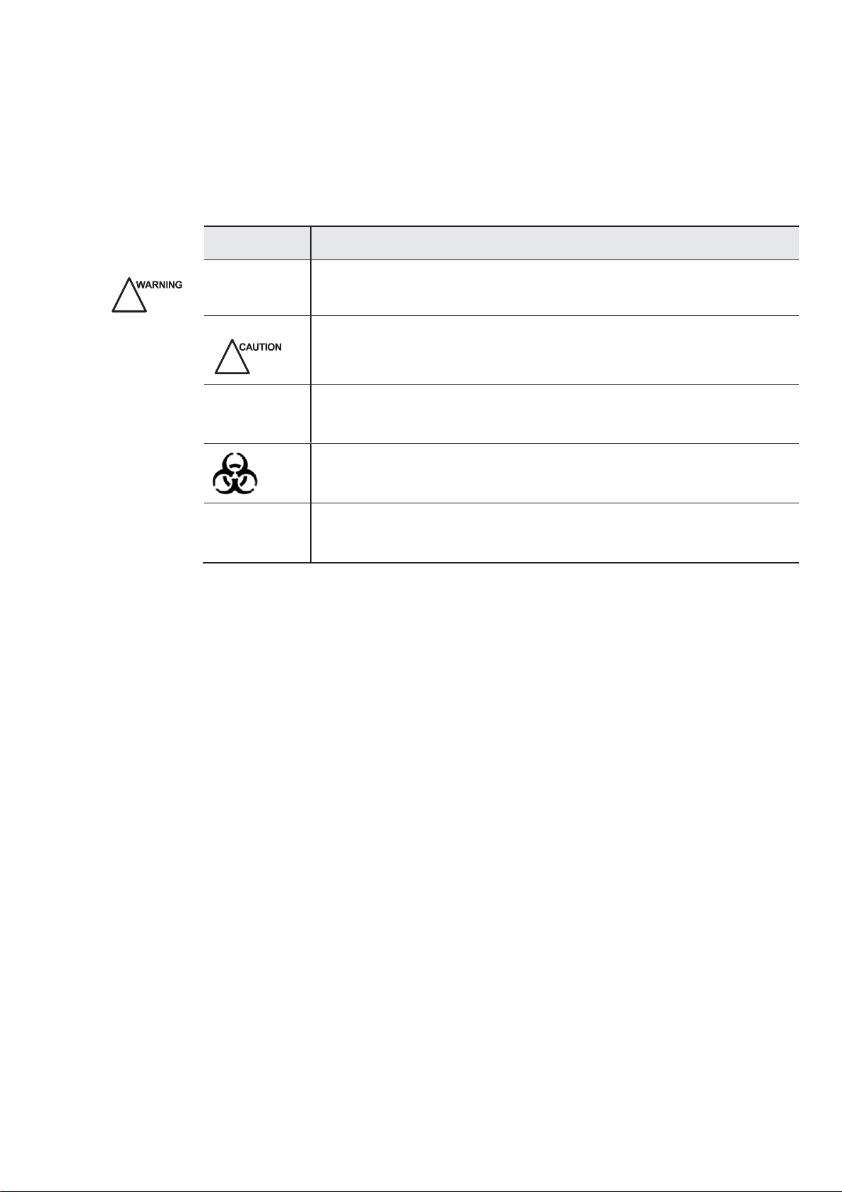
Signal words in this manual are defined as follows. Please understand their
meanings clearly before reading this manual.
Signal Word
Meaning
!
Indicates a potentially hazardous situation which, if not avoided, could
result in death or serious injury.
Indicates a potentially hazardous situation which, if not avoided, may
result in malfunction or damage of the system.
NOTE
Indicates precautions or recommendations that should be used in
operating the system.
Indicates a potentially biological hazardous situation which, if not
avoided, may result in disease transmission.
Boldface
d Word
Indicates keys and controls located on the control panel, or on-screen
objects such as menu items or keys.
Contact Information
Manufacturer: MEDISONO
Address: 3511 Silverside RD. Wilmington, DE 19810, United States

Digital Color Doppler Ultrasound System
Contents
Chapter 1 Introduction.......................................................................................1
Chapter 2 System Safetyand Maintenance.....................................................3
2.1
Safety Overview ................................................................................................3
2.2
Description of Symbols and Signal Words Used....................................................4
2.2.1
Symbols...................................................................................................... 4
2.2.3 Signal words...........................................................................................6
2.3
Messages ..........................................................................................................7
2.4
Adverse Effects and Precautions......................................................................7
2.5
Biological Safety................................................................................................7
2.6
Scanning Patients and Education .....................................................................8
2.6.1
Safe Scanning Guideline........................................................................8
2.6.2
Understanding the MI/TI Display...........................................................10
2.7
Environmental Requirements..........................................................................14
2.8
Electrical Requirements ..................................................................................14
2.9
Electrical Safety...............................................................................................15
2.10
Cautions for Using Accessories.......................................................................16
2.11
Environmental Protection ................................................................................16
2.12
System Transportation ....................................................................................17
2.12.1
Moving the System...............................................................................17
2.12.2
Transporting the System ......................................................................17
Chapter 3 SystemSpecifications.................................................................19
3.1
Intended Use................................................................................................................. 19
3.2
Standard System Configuration ......................................................................19
3.3
Physical Specifications....................................................................................19
3.4
System Overview.............................................................................................20
3.4.1
Right View.............................................................................................20
3.4.2
Left View...............................................................................................21
3.4.3
Peripheral Device Panel.......................................................................22
3.4.4
Keyboard ..............................................................................................23
Chapter 4 Starting the System...........................................................................29
4.1
Probe Connection............................................................................................29
4.2
Power On and Off............................................................................................29
4.2.1
Power On..............................................................................................30
4.2.2
Power Off..............................................................................................30
4.3
Peripheral Device............................................................................................31
4.3.1
Footswitch Connection.........................................................................31
4.3.2
Video Printer Connection ........................................................................ 31
4.3.3
Network Printer Connection .................................................................32
4.3.4
USB Printer Connection .......................................................................33
Basic UserManual i

Digital Color Doppler Ultrasound System
4.4
Patient Information ..........................................................................................33
4.4.1
Create NewPatient...............................................................................33
4.4.2
Patient Exam List..................................................................................43
4.4.3
DICOM Q/R...........................................................................................47
4.4.4
DICOM Queue......................................................................................49
4.4.5
PPS Screen ..........................................................................................50
4.4.6
Patient Exam Import/Export..................................................................51
4.5
Start Ultrasound Diagnosis..............................................................................53
4.6
Main Screen.....................................................................................................54
Chapter 5 SystemSetup...............................................................................55
5.1
General Setting.................................................................................................... 55
5.1.1
General.................................................................................................55
5.1.2
Display..................................................................................................57
5.1.3
Menu.....................................................................................................58
5.1.4
Storage.................................................................................................59
5.2
Peripheral ........................................................................................................60
5.3
Comment.............................................................................................................. 61
5.4
Bodymark.........................................................................................................62
5.5
Measure...........................................................................................................64
5.5.1
General.................................................................................................64
5.5.2
Menu.....................................................................................................66
5.5.3
Formula.................................................................................................67
5.6
Report..............................................................................................................68
5.7
DICOM.............................................................................................................69
5.7.1
DICOM Image Storage.........................................................................69
5.7.2
DICOM Storage Commitment.....................................................................71
5.7.3
DICOMWorklist....................................................................................72
5.7.4
DICOM MPPS.......................................................................................... 73
5.7.5
DICOM Print..........................................................................................74
5.7.6
DICOM Q/R...........................................................................................76
5.8
Remote Service...............................................................................................77
5.9
System Information..........................................................................................78
Chapter 6 B Mode.................................................................................................79
6.1
Starting B Mode...............................................................................................79
6.2
Parameter Adjustment.....................................................................................80
6.2.1
Focal Number................................................................................................81
6.2.2
Focal Span............................................................................................81
6.2.3
Chroma.................................................................................................82
6.2.4
Frequency.............................................................................................82
6.2.5
Acoustic Output Power.................................................................................82
6.2.6
Line Density..........................................................................................83
6.2.7
Sector Width and Position....................................................................83
6.2.8
Dynamic Range....................................................................................83
Basic UserManual ii

Digital Color Doppler Ultrasound System
6.2.9
Grayscale curve....................................................................................84
6.2.10
Persistence...........................................................................................84
6.2.11
μScan Function.....................................................................................84
6.2.12
Compound Imaging......................................................................................85
6.2.13
Trapezoidal Imaging.....................................................................................85
6.2.14
L-R Reverse..........................................................................................85
6.2.15
U-D Reverse.........................................................................................85
6.2.16
Rotation ................................................................................................86
6.2.17
Biopsy...................................................................................................86
6.2.18
B Gain...................................................................................................87
6.2.19
Focus....................................................................................................87
6.2.20
Depth....................................................................................................87
6.2.21
Time Gain Compensation (TGC)..........................................................88
6.3
Other B Mode Operations ...............................................................................89
6.3.1
Frozen Mode.........................................................................................89
6.3.2
Image Magnification .............................................................................89
6.3.3
Image Reverse (Left/Right)..................................................................90
6.3.4
Image Reverse (Up/Down)..........................................................................91
6.3.5
Dual Display Format.............................................................................91
6.3.6
Quad Display Format............................................................................... 92
6.3.7
Tissue Harmonic Imaging (THI)..................................................................93
6.3.8
Panoramic Imaging.......................................................................................94
Chapter 7 CFM Mode...........................................................................................95
7.1
Starting CFM Mode .........................................................................................95
7.2
Parameter Adjustment.....................................................................................96
7.2.1
Frequency.............................................................................................97
7.2.2
CFM Power....................................................................................................97
7.2.3
Resolution.............................................................................................97
7.2.4
Wall Filter..............................................................................................98
7.2.5
B Reject................................................................................................98
7.2.6
Persistence...........................................................................................98
7.2.7
Color Map................................................................................................. 98
7.2.8
FlowInvert ............................................................................................99
7.2.9
CFM Gain..............................................................................................99
7.2.10
Pulse Repetition Frequency .................................................................99
7.2.11
Steer...................................................................................................100
7.3
Other CFM Mode Operations........................................................................100
7.3.1
Frozen Mode.......................................................................................100
7.3.2
Image Magnification ...........................................................................101
7.3.3
B+CFM Real Time Dual Format .........................................................101
7.3.4
Quad Display Format.............................................................................101
Chapter 8 DPI Mode (Doppler Power Imaging)................................................ 103
8.1
Starting DPIMode..........................................................................................103
8.2
Parameter Adjustment...................................................................................104
Basic UserManual iii

Digital Color Doppler Ultrasound System
8.2.1
Frequency...........................................................................................105
8.2.2
DPI Power...................................................................................................105
8.2.3
Resolution...........................................................................................105
8.2.4
Wall Filter............................................................................................105
8.2.5
B Reject..............................................................................................105
8.2.6
Color Map...............................................................................................105
8.2.7
Persistence.........................................................................................105
8.2.8
DPIGain..............................................................................................105
8.3
Other DPI Mode Operations..........................................................................105
Chapter 9 TDI Mode...........................................................................................107
9.1
Starting TDI Mode..........................................................................................107
9.2
Parameter Adjustment...................................................................................108
9.2.1
Frequency...........................................................................................108
9.2.2
Power...........................................................................................................108
9.2.3
Resolution...........................................................................................108
9.2.4
B Reject..............................................................................................108
9.2.5
Color Map...............................................................................................108
9.2.6
Persistence.........................................................................................108
9.2.7
TDI Gain..............................................................................................108
9.3
Other TDIMode Operations..........................................................................109
Chapter 10 M Mode.............................................................................................. 111
10.1
Starting M Mode ............................................................................................111
10.1.1
Inactivated M Mode ............................................................................111
10.1.2
Activated M Mode...............................................................................112
10.2
Parameter Adjustment...................................................................................112
10.2.1
Display Format....................................................................................112
10.2.2
Sweep Speed......................................................................................113
10.2.3
Steer M...............................................................................................113
10.2.4
Chroma...............................................................................................113
10.2.5
Smoothness........................................................................................113
10.2.6
Video Invert.........................................................................................114
10.3
Other M Mode Operations.............................................................................114
10.3.1
Frozen Mode.......................................................................................114
10.3.2
M Line.................................................................................................115
10.3.3
Dual Display........................................................................................115
Chapter 11 PW Mode....................................................................................117
11.1
Starting PW Mode..........................................................................................117
11.1.1
Inactivated PW Mode .........................................................................117
11.1.2
Activated PW Mode............................................................................118
11.2
Parameter Adjustment...................................................................................118
11.2.1
Frequency...........................................................................................119
11.2.2
PW Power...........................................................................................119
11.2.3
Sweep Speed......................................................................................119
Basic UserManual iv
11.2.4
Dynamic Range..................................................................................119

Digital Color Doppler Ultrasound System
11.2.5
Wall Filter............................................................................................119
11.2.6
Chroma...............................................................................................119
11.2.7
Display Format ...................................................................................119
11.2.8
FlowInvert ..........................................................................................119
11.2.9
Video Invert.........................................................................................120
11.2.10
2D Refresh..........................................................................................120
11.2.11
Baseline..............................................................................................120
11.3
Other PW Mode Operations..........................................................................120
11.3.1
Frozen Mode.......................................................................................120
11.3.2
Spectral Doppler Line.........................................................................121
11.3.3
Sample Volume Gate..........................................................................121
11.3.4
FlowCursor.........................................................................................121
11.3.5
Baseline..............................................................................................121
11.3.6
Dual Display........................................................................................122
Chapter 12 CW Mode....................................................................................123
Chapter 13 Triplex Mode.....................................................................................125
13.1
B+CFM/TDI+M ..............................................................................................125
13.2
B+CFM/DPI/TDI+PW.....................................................................................125
Chapter 14 Miscellaneous Functions.............................................................127
14.1
Annotation......................................................................................................127
14.1.1
TextualAnnotation...............................................................................127
14.1.2
ArrowAnnotation.................................................................................128
14.2
Body Mark......................................................................................................128
14.3
Save and Review...........................................................................................130
14.4
Customize Exam Mode..................................................................................132
14.4.1
Create NewExam Mode.....................................................................132
14.4.2
Edit Exam Mode .................................................................................133
14.4.3
Import/Export Exam Mode..................................................................134
14.5
Print ...............................................................................................................134
14.6
ECG Module..................................................................................................135
14.6.1
Basic Procedures of ECG Operation..................................................135
14.6.2
Optimizing Parameters.......................................................................136
14.6.3
Reviewing ECG......................................................................................136
Chapter 15 Elastography.................................................................................137
15.1
Starting Elastography....................................................................................137
15.2
Parameter Adjustment...................................................................................139
15.2.1
Sample Box.....................................................................................139
15.2.2
Strain Process....................................................................................139
15.2.3
Strain Map..............................................................................................139
15.2.4
Transparency......................................................................................139
15.2.5
Persistence.........................................................................................140
15.2.6
Contrast..............................................................................................140
15.2.7
Frequency...........................................................................................140
Basic UserManual v
15.3
Other Elastography Mode Operations...........................................................140

Digital Color Doppler Ultrasound System
Chapter 16 3D............................................................................................................ 141
16.1
Starting 3D.....................................................................................................141
16.2
Parameter Adjustment...................................................................................143
16.2.1
Display Format....................................................................................143
16.2.2
Slice....................................................................................................143
16.2.3 ROI......................................................................................................144
16.2.4
Render Mode......................................................................................144
16.2.5
Zoom...................................................................................................145
16.2.6
Trace Cut............................................................................................145
16.2.7
Color...................................................................................................146
16.2.8
Transparency......................................................................................146
16.2.9
Brightness...........................................................................................147
16.2.10
Sweeping Mode..................................................................................147
16.2.11
Slice View...........................................................................................147
16.2.12
Restore...............................................................................................148
16.2.13
Print.....................................................................................................148
16.3 Other 3D Operations.........................................................................................149
16.3.1
Save....................................................................................................149
16.3.2
Review................................................................................................149
16.4 Exit.................................................................................................................................149
Chapter 17 4D............................................................................................................ 151
17.1 Inactivated 4D................................................................................................151
17.1.1 Enter Inactivated 4D...........................................................................151
17.1.2 ROI......................................................................................................152
17.1.3
Parameter Adjustment........................................................................152
17.1.4
Exit.....................................................................................................................152
17.2 Activated 4D Mode........................................................................................152
17.2.1
Enter Activated 4D Mode....................................................................152
17.2.2
4D Menu.............................................................................................154
17.2.3
Rotate Image..............................................................................................157
17.2.4
Zoom...................................................................................................157
17.2.5
Print.....................................................................................................157
17.2.6
Exit.....................................................................................................................157
17.3 Frozen 4D Mode............................................................................................158
17.3.1
Enter Frozen 4D Mode.......................................................................158
17.3.2
Parameter Adjustment........................................................................158
Chapter 18 Probes and Biopsy....................................................................... 161
18.1
Probe.............................................................................................................161
18.1.1
Available Probes.................................................................................161
18.1.2
Probe Usage.......................................................................................... 162
18.1.3
Cleaning the Probe................................................................................164
18.1.4
Disinfecting and Sterilizing the Probe.................................................164
Basic UserManual vi
18.1.5
Disinfecting or Sterilizing the Probe Cable............................................. 167
18.1.6
Storage and Transportation................................................................168

Digital Color Doppler Ultrasound System
18.2
Biopsy............................................................................................................169
18.2.1
Available Biopsy Brackets..................................................................169
18.2.2
Assembling the Biopsy Bracket..........................................................170
18.2.3
Preparing for a Biopsy........................................................................172
18.2.4
Verifying the Biopsy Bracket...............................................................173
18.2.5
Performing a Biopsy...........................................................................173
18.2.6
Cleaning the BiopsyBracket ..............................................................174
18.2.7
Sterilizing the Biopsy Bracket.............................................................174
18.2.8
Storage...............................................................................................175
Chapter 19 SystemMaintenance..................................................................177
19.1
Manufacturer Responsibility..........................................................................177
19.2
Cleaning the System.....................................................................................177
19.3
Maintenance Checks.....................................................................................178
19.4
Data Backup..................................................................................................179
19.5
Troubleshooting.............................................................................................179
19.6
Replacing the Fuse........................................................................................180
19.7
Equipment Disposal.......................................................................................180
19.8
Customer Service..........................................................................................180
Appendix A EMC Guidance and Manufacturer's Declaration........................ 181
Appendix B In Situ, Derated, and Water Value Intensities ...........................187
Appendix C Principle for Using Acoustic Power...........................................189
Appendix D Acoustic Output Data ................................................................191


Digital Color Doppler Ultrasound System
1
Basic User Manual
Chapter 1Introduction
This equipment is a full digital color Doppler ultrasound system for general application.
The high performances of this system using the advanced ultrasound Doppler im aging
technologies include full digital beam -former, wide dynamic range, multi-beam processing, etc.
The ergonomic user-friendly design enables user to customize the system according to the
specific application, and graphic exam icons assure you familiar with the system in few
minutes

2
Basic User Manual
Digital Color Doppler Ultrasound System
Chapter 2System Safety and Maintenance
2.1 SafetyOverview
This section discusses measures to ensure the safety of both the operator and patient.
To ensure the safety of both operat or and patient, please read the relevant details in this
chapter carefully before operating this system. Disregarding the WARNINGS or violation of
relevant rules may result in personal injury or even loss of life for operator or patient.
Users should observe the following PRECAUTIONS:
This system complies with Type BF general equipm ent, and the EN60601-1 standard.
Do not modify this system in any way. Necessary modifications must be made only by
the manufacturer or its designated agents.
This system has been fully adjusted at the factory. Do not adjust any fixed adjustable
parts.
Not to position this equipment to make it difficult to operate the disconnectiondevice.
In the event of a malfunction, turn off the system immediately and inform the
manufacturer or its designated agents.
The power cable of the system should only be connected to a grounded power socket.
Do not remove the ground cable for any reason.
Only connect this system, either electronically or mechanically, with devices that
comply with the E N60601-1 standard. Recheck the leakage current and other safety
performance indices of the entire system to avoid pot ential system damage caused
by leakage from a current superposition.
In the environment that patient is 1.8 meters (6 feet ) around, connect peripherals to
the auxiliary power outlet which is capable of is olation protection, or power the
peripherals by auxiliary output cable or isolation trans former complied with EN
60601-1 or the power input of the same safety level.
Leave at least 20cm at the back and bot h sides of the ultras ound system for
ventilation. Otherwise, the temperature rise could cause failures.
The system does not inc orporate any specialized protective meas ures in the event it
is configured with high-frequency operation devices. The operator should use
CAUTION in these types of applications.
The system should be installed only by personnel authorized by the manufacturer. Do
not attempt to install the system yourself.
Only an authorized service engineer may perform maintenance.
Only a qualified operator, or someone under qualified supervision, should use the
system.

3
Basic User Manual
Digital Color Doppler Ultrasound System
Do not use this system in the presence of flammable substances or an explosion may
occur.
Connect the earth conductor only before powering on the system. Dis connect the
grounding cable only after powering off the system. Otherwise, there is a danger of
electric shock.
Do not continuously scan the same part of a patient or expose the patient to
prolonged scanning. Doing so may harm the patient.
Do not expose the fetus to prolonged scanning in the Doppler mode.
When using the system for ultrasound testing, use only qualified ultrasound gel that
complies with system standards.
Do not use the switch at the back of the unit for normal shut down. Always use the
power-on button in the keyboard area.
Do not unplug probe when the system is in active operation. Doing so may damage
the probe. Always go to EXAM screen when need to remove the probe.
Toprevent from arm or neck injury, the operator should not stay at the same position
for too long during patient scanning without taking break.
Do not place other objects on top of the control panel. Do not sit on the control panel
or other part of the ultrasound system.
Do not knock or shake the ultrasound system.
Do not put liquid on top of the main unit.
For proper disposal of this product, please contact our service department.
2.2 Descriptionof Symbols and SignalWords Used
2.2.1 Symbols
The following symbols are utilized on the product or the label and package thereof.
Symbol
Description
Caution
Warning: dangerous voltage
OFF (Mains power switch OFF)
ON (Mains power switch ON)

4
Basic User Manual
Digital Color Doppler Ultrasound System
“ON” / “OFF” (push-push)
NOTE: Each position, "ON" or "OFF", is a stable position.
Protective earth (ground)
Equipotentiality
Alternating current
Type BF Applied Part
Degree of IP protection.
Non-ionizing electromagnetic radiation.
NOTE: Ultrasound scanner transmits acoustic waves.
Manufacturer inform ation (including the name and the address
of the manufacturer).
Date of manufacture..
Follow instructions for use
Network Port
Control port of color video printer
USB Port
Video Input

5
Basic User Manual
Digital Color Doppler Ultrasound System
Video Output
Fragile.
Keep dry.
No stacking
Maximum stacking limit of packages. Maximum of two layers
allowed!
Keep this way upward.
Serial Number.
NOTE: Unique number for the ultrasound system.
This symbol indicates that waste electrical and electronic
equipment must not be disposed of as unsorted municipal
waste and must be collected separately. Please contact an
authorized representative of the manufacturer for inform ation
concerning the decommissioning of your equipment.
2.2.3 Signal words
The following signal words are used throughout the user manual.
Signal words
Description
Warning! Follow these instructions to avoid personal injury or
system damage.
Caution! Follow these instructions to avoid system damage.
Note Follow these instructions to obtain additional helpful
information.

6
Basic User Manual
Digital Color Doppler Ultrasound System
2.3 Messages
All the messages generated by this ultrasound system are self-explanatory. However, you may
encounter the following situations.
License renewal
When the validity of the license is less than 7 days, the message appears on the
preparation mode screen. System function will not be affected until the license is
expired, in which case the message on the above left will appear when the user
clicks an application mode icon. Please contac t us for license renewal.
Auto Freeze ultrasound scan
In order to protect the operator or the patient from accidentally receiving excessive
acoustic energy, the system automatically stops the real time scan (no on-screen
message will be provided) and returns the Freeze mode if there has been no user
activity for 10 minutes. The user m ay resume the scan by pressing the Freeze key
to return to the real time scan, no prerequisite action is required.
2.4 AdverseEffectsand Precautions
This ultrasound system, same as all other diagnostic ultrasound system in the m arket, should
be used only for clinically appropriate reasons, for the shortest period of time and at power
settings as low as reasonably achievable (ALARA).
The American Institute of Ultrasound in Medicine (A IUM ) principle of As Low As Reasonably
Achievable (ALA RA) is recommended during selection of the output of ultrasound power. Try
not to aim probe at the sam e spot in tissue for a long period of time unless it is necessary for
diagnostic purpose. This system, as a basic imaging system with the Doppler and Color
Doppler feature generates acoustic power that is below pre-enactment levels, which are
generally considered to be safe for the respective applications.
2.5 BiologicalSafety
This product, as with all diagnostic ultrasound equipm ent, should be used only for valid
reasons and should be used both for the shortest period of time and at the lowest power
settings necessary (
ALARA
-As Low As Reasonably Achievable) to produce diagnostically
acceptable images.
The AIUM offers the following guidelines:
Clinical Safety Quoted from AIUM
Approved M arch 26, 1997
Diagnostic ultrasound has been in use since the late 1950s. Given its k nown
benefits and recogniz ed efficacy for m edical diagnosis, including use during
human pregnancy, the American Institute of Ultrasound in Medicine herein
addresses the clinical safety of such use:
There are no confirmed biological effects on patients or instrum ent operat ors

7
Basic User Manual
Digital Color Doppler Ultrasound System
caused by exposures from present diagnostic ultrasound instruments. Although
the possibility exists that such biological effects may be identified in the future,
current data indicate that the benefits to patients of the prudent use of diagnostic
ultrasound outweigh the risk s, if any that may be present.
Heating:
Elevating tissue temperature during obstetrical examinations creat es medical concerns. At the
embryo development stage, the rise in temperature and the length of time exposed to heat
combine to determine potential detriment al effects. Exercise CAUTION particularly during
Doppler/Color exams.
The Thermal Index (TI) provides a statistical estimate of the potential tem perature elevation (in
centigrade) of tissue temperature. Three forms of TI are available: TIS, for soft tissue
exposures; TIB, for instances when bone lies near the beam focus; and TIC, for the heating of
bone situated close to thetransducer.
Cavitation:
Cavitation m ay occur when sound passes through an area that contains a cavity, such as a
gas bubble or air pocket (in the lung or intestine, for example). During the process of cavitation,
the sound wave may cause the bubble to contract or resonate. This oscillation may cause t he
bubbles to explode and dam age the tissue. The M echanical Index (MI) has been creat ed to
help users accurately evaluate the likelihood of cavitation and the related adverse effects.
2.6 ScanningPatientsand Education
The Track-3 or IE C60601-2-37 output display standard allows users to share the responsibility
for the safe use of this ultrasound system. Follow these usage guidelines for safe operation:
In order to m aintain proper cleanliness of the transducers, always clean them
between patients.
Always use a new disinfected sheath on all EV/ER probes during every exam.
Continuously move the probe, rather than staying in a single spot, to avoid elevated
temperatures in one part of the patient’s body.
Move probe away from the patient when not actively scanning.
Under stand the meani ng of the TI, TIS, TIB, TIC, and MI output display, as well as the
relationship between these parameters and the thermal/cavitation bioeffect to the tissue.
Expose the patient to only the very lowest practical transmit power levels for the
shortest possible time t o achieve a satisfactory diagnosis (ALA RA - As Low As
Reasonably Achievable).
2.6.1
Safe Scanning Guideline
1.
Ultrasound should only be used for medical diagnosis and only by trained m edical
personnel.
2.
Diagnostic ultrasound procedures should be done only by personnel fully trained in
the use of the equipm ent, in the interpretation of the results and images, and in the
safe use of ultrasound (including education as to potentialhazards).

8
Basic User Manual
Digital Color Doppler Ultrasound System
3.
Operators should understand the likely influence of t he m achine controls, the
operating mode (e.g. B-mode, color Doppler imaging or spectral Doppler) and probe
frequency on thermal and cavitation hazards.
4.
Select a low setting for each new patient. Output should only be increased during the
examination if penetration is still required to achieve a satisfactory result, and aft er
the Gain control has been moved to its maximumvalue.
5.
Maintain the shortest examination time necessary to produc e a useful diagnostic
result.
6.
Do not hold the probe in a fixed position for any longer than is necessary. It should be
removed from the patient whenever there is no need for real-time imaging or spectral
Doppler acquisition. The freeze frame and Cine loop capabilities allow images to be
reviewed and discussed without exposing the patient to continuous scanning.
7.
Do not use endo-cavity probes if there is noticeable self-heating of the probe when
operating in the air. Although applicable to any probe, take particular care during
trans-vaginal exams during the first eight weeks of gestation.
8.
Take particular care to reduce output and minimize exposure time of an em bryo or
fetus when the temperature of the mother is alreadyelevated.
9.
Take particular care to reduce the risk of thermal hazard during diagnostic ultrasound
when exposing an embryo less than eight weeks after gestation; or the head, brain or
spine of any fetus or neonate.
10.
Operators should continually monitor the on -screen therm al index (TI) and
mechanic al index (MI) values and use control settings that keep these settings as
low as possible while still achieving diagnostically useful results.
In obstetric examinations, TIS (soft tissue thermal index) should be monitored during
scans carried out in the first eight weeks after gestation, and TIB (bone thermal index)
thereafter. In applications where the probe is very close to bone (e.g. trans -cranial
applications), TIC (cranial thermal index) should be monitored.
MI>0.3 There is a possibility of minor damage to neonatal lung or intestine. If such
exposure is necessary, reduce the exposure time as much as possible.
MI>0.7 There is a risk of cavitation if an ultrasound contrast agent containing gas
micro-spheres is being used. There is a theoretical risk of cavitation wit hout the
presence of ultrasound contrast agents. The risk increases with MI values above
this threshold.
TI>0.7 The overall exposure time of an em bryo or fetus should be restricted in
accordance with Table 2-1 below as a reference.
TI
Maximum exposure time (minutes)
0.7
60
1.0
30
1.5
15
2.0
4
2.5
1
Table 2-1
Maximum recommended exposure times for an embryo or fetus

9
Basic User Manual
Digital Color Doppler Ultrasound System
11.
Non-diagnostic use of ultrasound equipment is not generally recomm ended.
Examples of non-diagnostic uses of ultrasound equipment include repeated scans
for operator training, equipment dem onstration using normal s ubjects, and t he
production of souvenir pictures or videos of a fetus. For equipm ent of which t he
safety indices are displayed over their full range of values, the TI should always be
less than 0. 5 and the M I should always be less than 0.3. A void frequent repeat ed
exposure of any subject.
Scans in the first trimester of pregnancy should not be carried out for the sole
purpose of producing souvenir videos or photographs, nor should their production
involve increasing the exposure levels or extending the scan times beyond those
needed for clinical purposes.
12.
Diagnostic ultrasound has the potential for both fals e positive and false negative
results. Misdiagnosis is far more dangerous than any effect that might result from the
ultrasound exposure. Therefore, diagnostic ultrasound should be performed only by
those with sufficient training and education.
2.6.1.1 Temperature Display for Transducers Intended for Internal Use
For transducers intended for internal applications, e.g. the endocavitary transduc ers, the
transduc er tip tem perature is displayed on the screen. To protect the patient against the harm
of excessive temperature, the system automatically turns off the trans ducer when the
temperature of the transducer reaches a threshold temperature.
2.6.2 Understanding the MI/TI Display
Track-3 follows the Output Display Standard for systems that include fetal Doppler applications.
The acoustic output will not be evaluated on an application -specific basis, but the global
maximum de-ratedI
SPTA
must be ≤720 mW/cm² and either the global maximum MI must be ≤
1.9 or the global maximum de -rated ISPTA must be ≤ 190 W/cm². An exception is for ophthalmic use,
in which case the TI=max (TIS_as, TIC) is not to exceed 1.0; ISPTA 3 ≤ 50mW/cm², and MI
≤ 0.23. Track-3 gives the user the freedom to increase the output acoustic power for a specific
exam, and still limit output acoustic power within the global maximum de-rated I
SPTA
≤ 720
mW/cm² under an Output Display Standard.
For any diagnostic ultrasonic systems, Track -3 provides an Output Indices Display Standard.
The diagnostic ultrasound systems and its user manual contain the information regarding an
ALARA (As Low As Reasonably Achievable) education program for the clinical end-user and
the acoustic output indices, MI and TI.
The MI describes the likelihood of cavitation, and the TI offers the predicted maximum
temperature rise in tissue as a result of the diagnostic examination.
In general, a temperature increase of 2.5°C must be present consistently at one spot for 2
hours to cause fetal abnorm alities. Avoiding a local temperature rise above 1°C should ensure
that no thermally induced biologic effect occurs.
When referring to the TI for potential thermal effect, a TI equal to 1 does not mean the
Table of contents
Other MediSono Medical Equipment manuals
Popular Medical Equipment manuals by other brands

Enraf Nonius
Enraf Nonius TENSMED S82 Instructions for use

COOK Medical
COOK Medical Saeed Series manual

Orthopedic Systems
Orthopedic Systems Jackson Spinal Table System user guide

AtriCure
AtriCure ASU3-230 user manual

Little Martin’s
Little Martin’s BFD1609 user manual

Stryker
Stryker Power-PRO XT Operation manual

Flaem
Flaem Pro OxyLast Med Easy P0613EM User instruction manual

Select Medical
Select Medical OLA 8 user manual

Bioness
Bioness L300 Go Clinician's Reference Card

Dr. Mach
Dr. Mach LED 6MC user manual

Ambu
Ambu Oval Plus Neonate Instructions for use

Diaglobal
Diaglobal Duo Photometer plus DP 210 operating manual