Morita Veraview X800 User manual

INSTRUCTIONS FOR USE
Cephalo
This manual is for making cephalo exposures.
Use it along with the manual for panorama and CT exposures.

2Instructions for Use 2018-04-11
1 Prevent Accidents ................................................................................................. 3
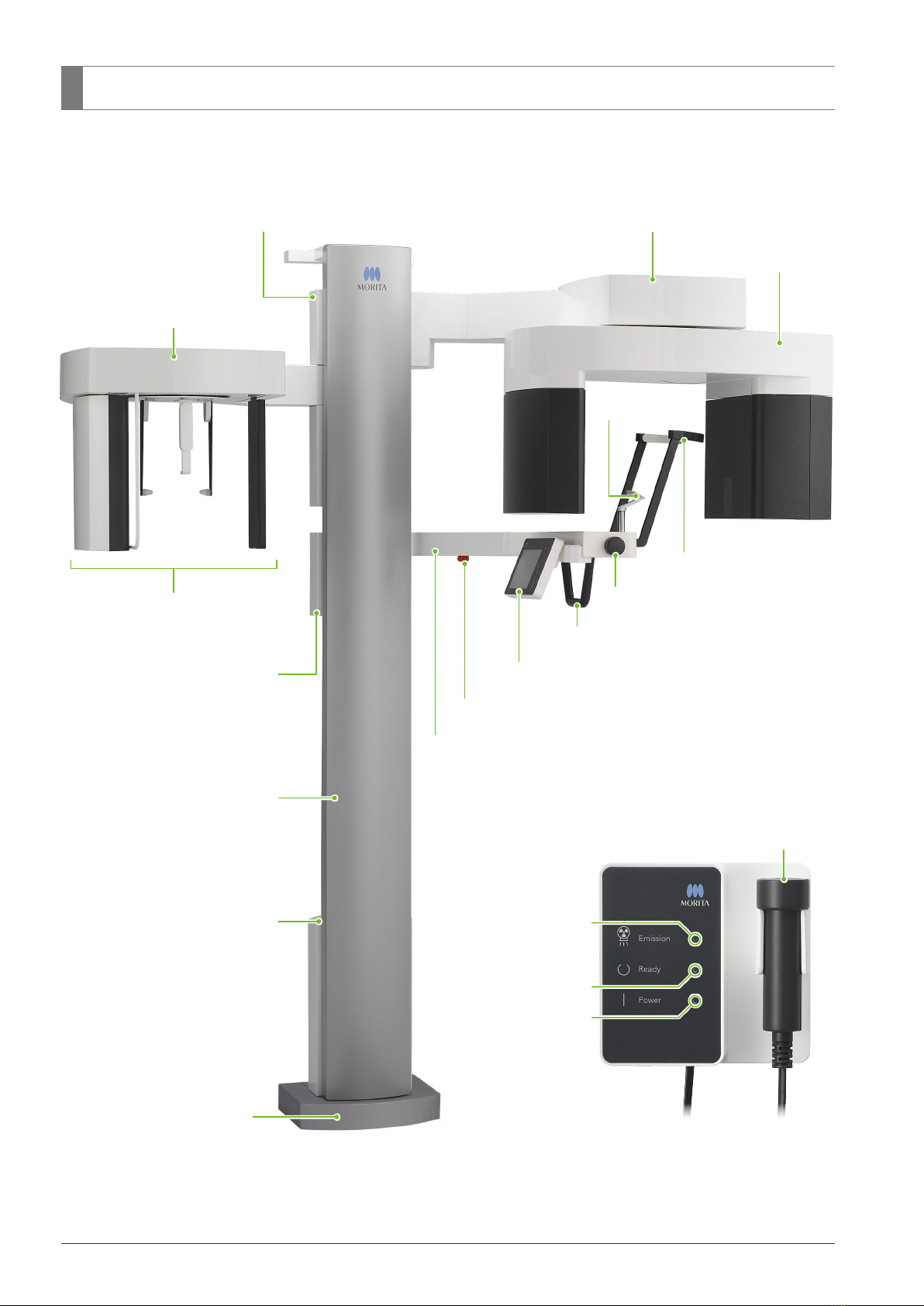
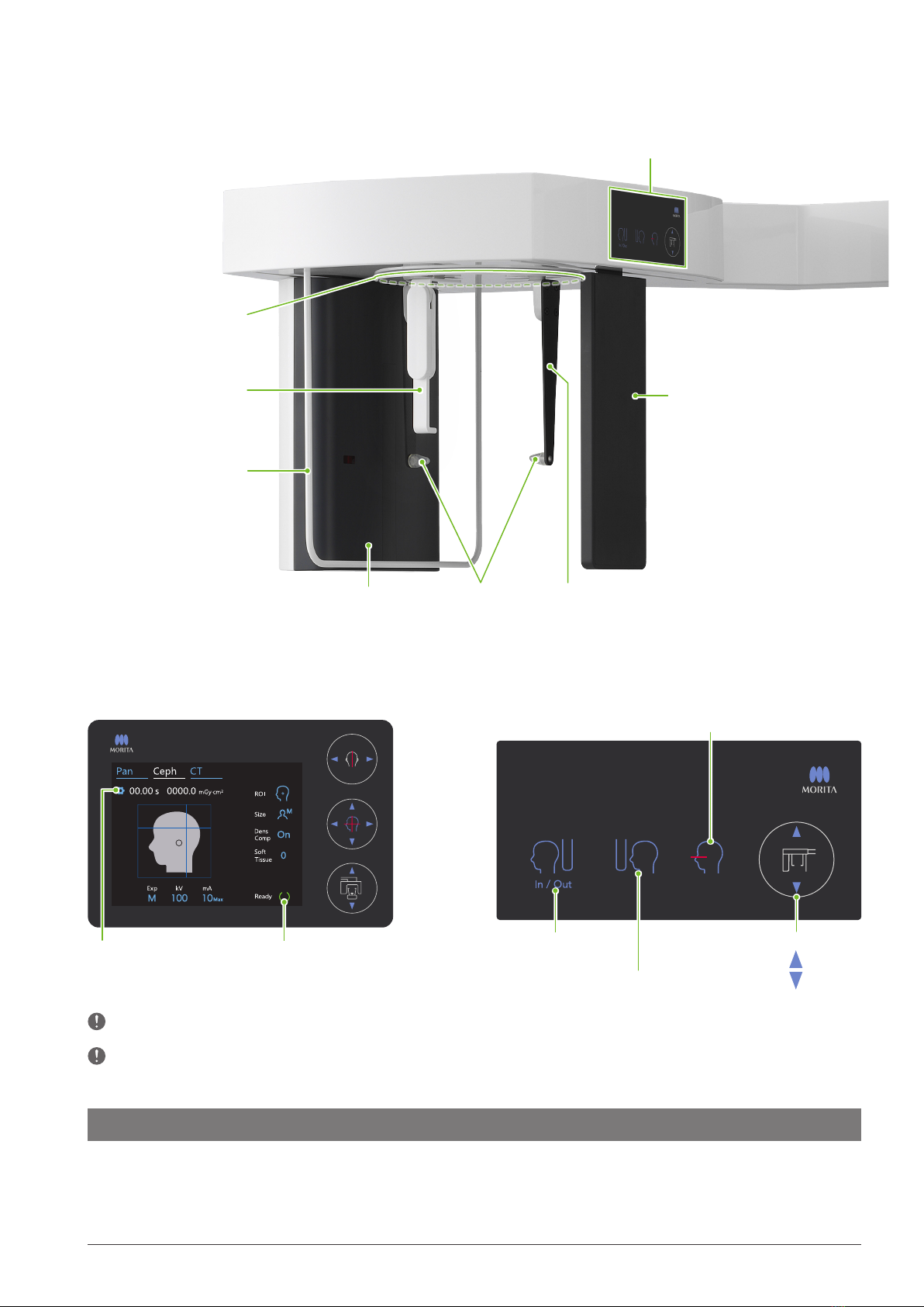
2 Parts Identification ............................................................................................... 4
3 Before and After Use ............................................................................................ 6
3.1 Operation Conditions............................................................................................................. 6
3.2 Set Up ..................................................................................................................................... 6
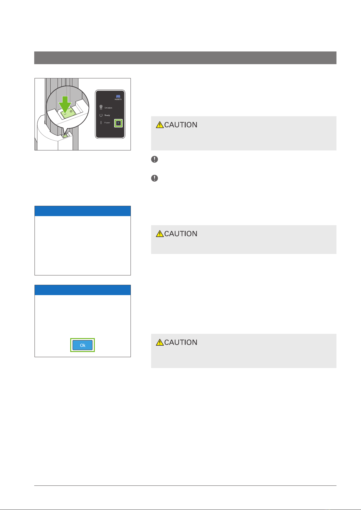
3.3 Start-up Inspection............................................................................................................... 10
3.4 After Use ............................................................................................................................... 11
4 Cephalo Exposure.............................................................................................. 12
4.1 ExposureTypes and Functions............................................................................................ 12
4.1.1 Exposure Area (ROI: Region Of Interest) .................................................................................... 12
4.1.2 Partial Cephalo ............................................................................................................................ 13
4.1.3 Density Compensation (Dens Comp).......................................................................................... 13
4.2 Operation and General Settings ......................................................................................... 14
4.2.1 Cephalo Display........................................................................................................................... 14
4.2.2 Settings....................................................................................................................................... 15
4.2.3 Positioning Beam ........................................................................................................................ 15
4.3 Lateral, PA, and 45° Angle Exposures ................................................................................ 16
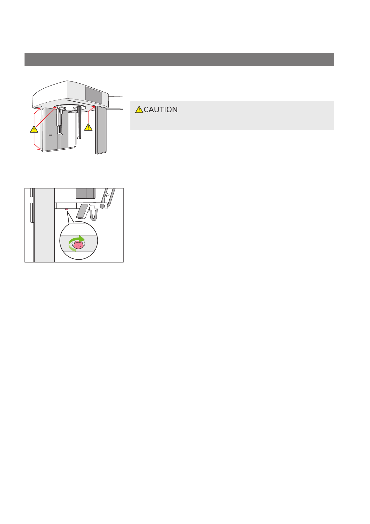
4.3.1 Preparation.................................................................................................................................. 16
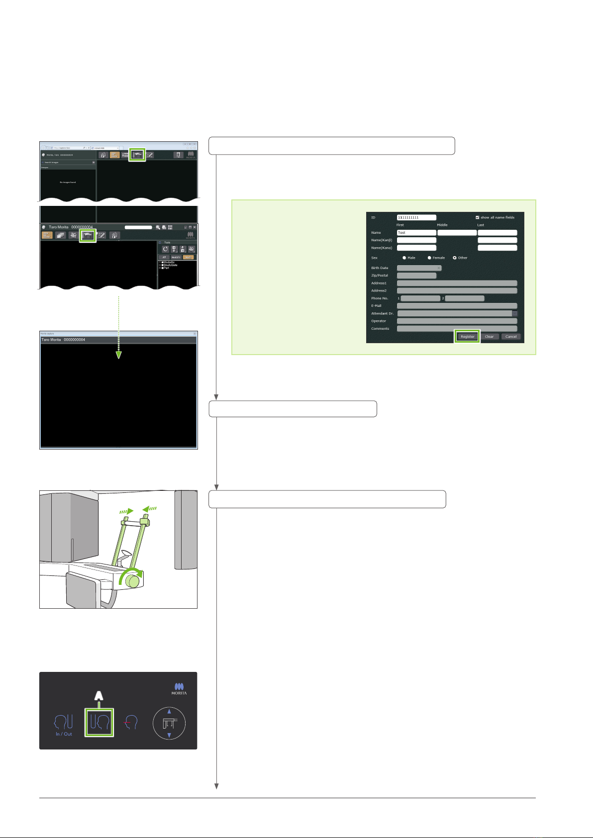
4.3.2 Patient Entry and Positioning ......................................................................................................22
4.3.3 Exposure .....................................................................................................................................25
4.3.4 Patient Egress.............................................................................................................................26
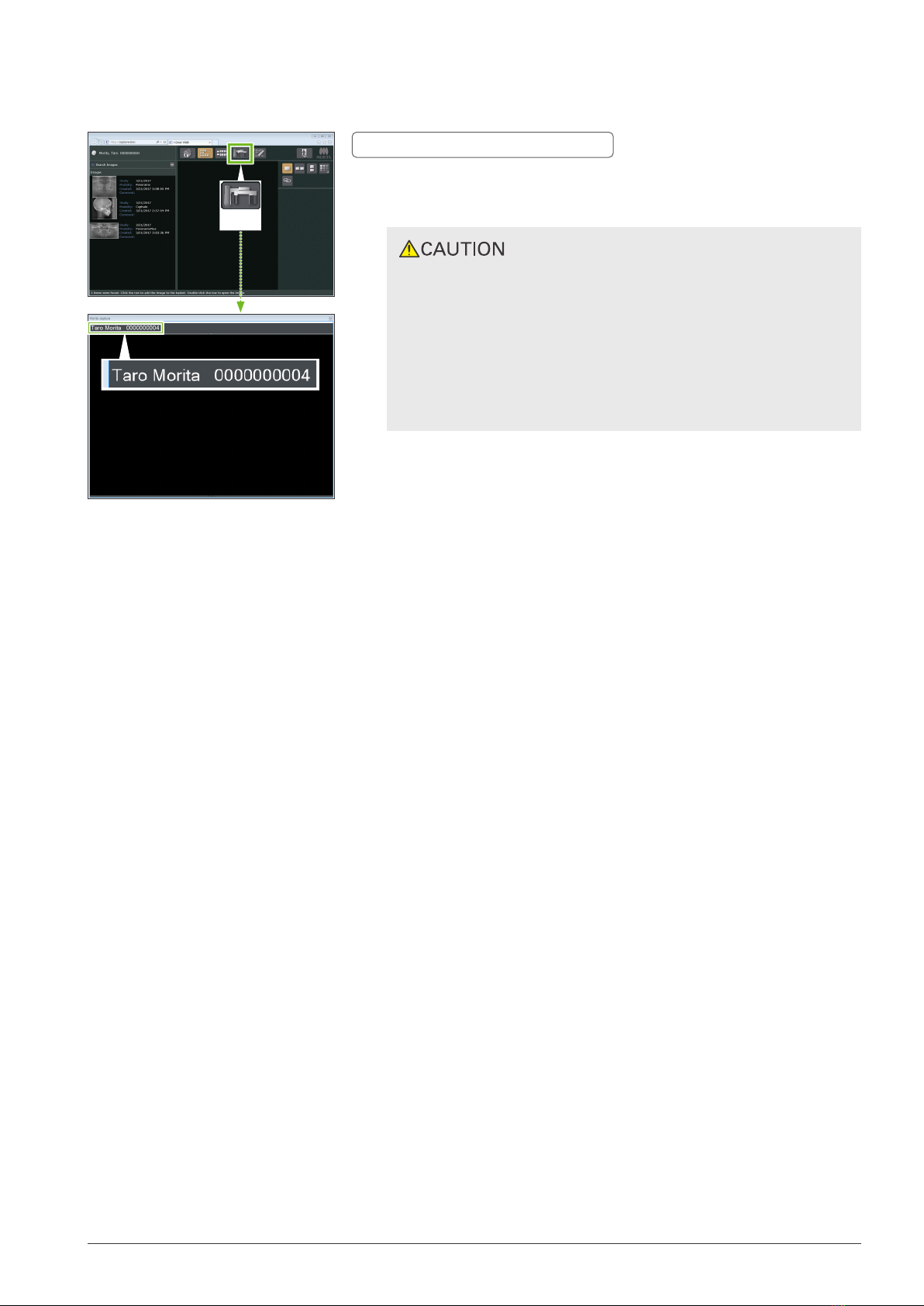
4.3.5 Image Transmission.....................................................................................................................27
4.4 Hand Exposure..................................................................................................................... 29
4.4.1 Preparation..................................................................................................................................29
4.4.2 Patient Entry and Positioning ......................................................................................................32
4.4.3 Exposure .....................................................................................................................................33
4.4.4 Patient Egress.............................................................................................................................34
4.4.5 Image Transmission.....................................................................................................................34
4.5 Cephalo Image Enhancement............................................................................................. 35
4.5.1 AIE (Auto Image Enhancement)..................................................................................................35
4.5.2 Examples of AIE Images.............................................................................................................37
4.6 Notes for Exporting Cephalo Data to Analysis Software .................................................. 39
5 Maintenance, Parts Replacement, and Storage............................................... 40
5.1 Maintenance......................................................................................................................... 40
5.2 Replacement Parts ............................................................................................................... 41
5.3 Storage.................................................................................................................................. 41
6 Troubleshooting .................................................................................................. 42
6.1 Troubleshooting.................................................................................................................... 42
6.2 Error Messages .................................................................................................................... 42
Table of Contents

3
Instructions for Use 2019-03-22
1.2 Prevent Accidents
Most operation and maintenance problems result from insucient attention being paid to basic safety pre-
cautions and not being able to foresee the possibilities of accidents.
Problems and accidents are best avoided by foreseeing the possibility of danger and operating the unit in
accordance with the manufacturer’s recommendations. First, thoroughly read all precautions and instruc-
tions pertaining to safety and accident prevention; then, operate the equipment with the utmost caution to
prevent either damaging the equipment itself or causing bodily injury.
The following symbols and expressions indicate the degree of danger and harm that could result from
ignoring the instructions they accompany:
The user (i.e., healthcare facility, clinic, hospital etc.) is responsible for the management, maintenance and
use of medical device.
Disregarding the information on safety is considered ABNORMAL USE.
This equipment must only be used by dentists and other legally licensed professionals.
Do not use this equipment for anything other than its specified dental X-ray exposure purpose.
Caution: Federal law restricts this device to sale by or on the order of a dentist and a licensed healthcare
practitioner.(for USA)
A hazard with a medium risk of injury or death if not avoided.
A hazard with a low risk of minor or moderate injury if not avoided.
This informs the user of important points concerning operation or the risk of
equipment damage.
1Prevent Accidents
This manual is for making cephalo exposures with the Veraview X800. It must be used along with the
Veraview X800 manual for panorama and CT exposures. Keep this manual in a readily accessible place for
quick and easy reference.
1.1 Attention Customers
Trademarks (™) and Registered Trademarks (®) :
The names of companies, services, etc. used in this manual are either trademarks or registered trademarks.
© 2017 J. MORITA MFG. CORP.

4Instructions for Use 2017-03-03
2Parts Identification
⹅Main Unit
Temporal Stabilizer
Patient Handle
Control Panel
Emergency Stop Switch
Control Panel Support
Column
Chinrest
Base
Cephalo Unit
Lift (lower)
Lift (upper)
Arm
Temporal Stabilizer Knob
Arm Support
Power Switch
Cephalo Support
⹅Control Box Emission Switch
Emission LED
Ready LED
Power LED

5
Instructions for Use 2020-03-23
Do not press down with excessive force on either of the control panels. Do not press on the panels with any sharp objects like ballpoint
pens or fingernails etc.
Do not use the Beam On/O or Lift Up/Down switches while touching some other part of the panel.
Blue icons and the Ready key are activated by touch.
Settings Key Ready Key
⹅Cephalo Unit
Ear Rods Ear Rod Plate
Nasion Plate
Patient Guard
Cephalo Control Panel
Cephalo Slit
X-ray Detector
Head Positioner
⹅Control Panel
Up and Down Switches
Up
Down
In/Out Switch
Exposure Start Position Switch
Beam On/O Switch
Patient Positioning Tools and Consumable Parts
• Hand Plate (1)
• Ear Rods (2)
●Main Unit ●Cephalo Unit

6Instructions for Use 2018-04-11
3Before and After Use
●Use the Veraview X800 under the following conditions:
Temperature: +10°C to +35°C (+50°F to +95°F)
Humidity: 30% to 75% (without condensation);
Atmospheric Pressure: 70 kPa to 106 kPa
* If an accident occurs, the equipment must not be used until repairs have been completed by a qualified
and trained technician authorized by the manufacturer.
* Have patients remove glasses, earrings and any other accessories that might interfere with the exposure.
* Before use make an initial inspection to make sure the unit will operate properly and safely.
3.1 Operation Conditions
3.2 Set Up
3.2.1 Start i-Dixel WEB
Start the i-Dixel or i-Dixel WEB software (hereinafter referred to
as “i-Dixel WEB”).
1. Start i-Dixel or i-Dixel WEB
Enter the patient ID in the search field and click the search icon (A).
To use the patient list, select a patient and then double-click it.
2. Retrieve a registered patient
To begin, register a patient. Click the icon Bto register a
new patient. Fill out the form that appears and then click the
Register button.
●Register a New Patient
An image list will appear.
* Patient ID, Name and
Sex are required items.
i-Dixel WEB
i-Dixel
A
B
i-Dixel WEB
A
B
i-Dixel

7
3.2 Set Up
Instructions for Use 2019-03-22
C
3. Open X800 Exposure window
Click the X800 Exposure Window icon (C).
When the window opens, an exposure can be made.
•When a patient is selected with i-DixelWEB, the patient name appears on the
title bar for the X800 Exposure Window. Before making the exposure, make sure
the name on the title bar is the name of the patient subject to the exposure. If
it is not the right name, close the window, and then click the icon (C) to reopen
the window. Check that the right name appears on the title bar, and then make
the exposure. If the wrong name is on the title bar, the exposure data will be
saved for the wrong patient.
• If multiple tabs or windows are open for i-Dixel WEB, processing can become
unstable and this could lead to saving data in the wrong patient file or not being
able to make the exposure. Do not fail to close all tabs and windows before
clicking the icon (C) for the X800 Exposure Window.
* Do not fail to open the X800 Exposure Window before making
an exposure.
* For details refer to the Instructions for Use for i-Dixel WEB.

8
3 Before and After Use
Instructions for Use 2017-04-10
●In Case of Emergency
Press the Emergency Stop switch. This will stop the arm rotation and
X-ray emission.
* Never use this switch except in the case of an emergency.
●After Pressing the Emergency Stop switch.
1.
Guide the patient away from the unit and turn o the Power switch.
2. Restore the unit to a safe condition.
3. Turn the Emergency Stop switch in the direction shown by the
arrow in the illustration until it clicks to release it.
4. Restart the computer.
5. Turn on the Power switch.
6. Check the panorama, CT, and cephalo exposure operation.
If the unit cannot be returned to a safe condition or will not operate,
contact your local dealer or J. MORITA OFFICE.
⹅Emergency Stop Switch
3.2.2 Safety Check for Moving Parts
For safety, make sure that fingers will not be pinched before moving
any parts.
• Keep fingers away from gaps and openings of moving parts such as the head posi-
tioner as well as the holes on the support column.

9
3.2 Set Up
PC and cassette communication check
Please wait while communication between
the digital cassette and PC is verified.
Ok
Initialization
The unit will move to its initial position.
The arm will move in multiple directions
so ensure the immediate area is clear of
obstructions before proceeding.
If a patient is positioned in the unit,
have them exit the unit before proceeding.
Instructions for Use 2019-03-22
3.2.3 Start Main Unit
Press the side of the Power switch on the lower part of the col-
umn that is marked with a line (
|
).
The unit will turn on and the blue Power LED on the control box
will light up.
• Do not press the Power switch if the patient is near or inside the equipment.
Otherwise, the arm will rotate and the control panel support will move and could
injure the patient.
If the Emergency Stop switch has been inadvertently pressed while the unit was
being cleaned etc., the unit cannot be turned on. Release the Emergency Stop
switch, and then turn on the unit.
When starting up the Veraview X800 right after turning it o (e.g., rebooting the
equipment), wait at least 5 seconds to turn it on again. Failure to do so could
result in malfunction or damage to the equipment.
Then the “Initialization” dialogue box will appear.
If the patient is already in position, have him step away from the
equipment.
Check the area and then click the “Ok” button.
The arm will move to the patient entry position.
• If the temporal stabilizers are open, a message will appear warning to check
them. The arm might hit them so turn the knob and close them.
The “PC and cassette communication check” dialogue box will
appear.
• Do not fail to move the patient away from the equipment and check the area for
safety before initializing the equipment. Otherwise, the arm might move and it
could hit the patient.

10
3 Before and After Use
A
i-Dixel WEB
i-Dixel
Instructions for Use 2017-10-23
Touch the Ceph key on the control panel.
Set the exposure conditions as shown below.
• Region Of Interest (ROI): Lateral
• Exposure Setting (Exp): “M” (manual)
• Tube Voltage (kV): 60 kV
• Tube Current (mA): 2 mA
Turn the temporal stabilizer knob and close the stabilizers completely.
Press the Ready key to move the X-ray head and the arm into
their cephalo positions.
Check that the Ready LED on the control panel or the control box
is on.
Touch the Exposure Start Position switch (A) on the cephalo con-
trol panel to move the cephalo unit to its exposure start position.
Hold down the Emission switch and check the following items:
• X-rays are being emitted.
• The Emission LED is on and the melody is playing.
• X-rays emission stops when the exposure is completed.
• The Emission LED turns o and the melody stops.
Release the Emission switch.
3.3 Start-up Inspection
Before use make a start-up inspection to make sure the unit will operate properly and safely.
Select the test patient used for the start-up inspection from the
i-DixelWEB patient list and display the image list for it.
To begin, the test patient
must be registered in
i-DixelWEB. Click the
Patient Registration Win-
dow
icon to display the
registration window, fill
out the form and then
click the Register button.
●First Time Only
3.Check operation for cephalometric exposure
1. Open the image list for the start-up inspection
Click the X800 Exposure Window icon to open it.
2. Open X800 Exposure window

11
3.4 After Use
Instructions for Use 2019-03-22
A message will appear in i-DixelWEB that says “Transferring
image!”, and after about 30 seconds the inspection image will
appear.
Delete the data acquired during the inspection exposure.
3.4 After Use
3.4.1 Turn O the Unit
Press the side of the Power switch marked with a circle ( ).
The unit will turn o. The Ready and Power LEDs will turn o.
• Do not fail to turn o the Power switch.This prevents the risk of current leakage, inad-
vertent operation, etc.
4.Image Display
5.Delete the inspection data
When starting up the Veraview X800 right after turning it o (e.g., rebooting the equip-
ment), wait at least 5 seconds to turn it on again. Failure to do so could result in mal-
function or damage to the equipment.

12
Lateral Exposure
PA Exposure
Instructions for Use 2017-04-26
4.1 Exposure Types and Functions
4Cephalo Exposure
4.1.1 Exposure Area (ROI: Region Of Interest)
Lateral cephalometric exposure.
⹅Lateral
PA cephalometric exposure.
⹅PA (Posterior-Anterior)
Cephalometric exposure at 45° angle.
⹅45° Angle
Cephalometric hand exposure.
⹅Hand

13
4.1 ExposureTypes and Functions
Partial Cephalometric Exposure
Instructions for Use 2017-04-26
This is used for an image that will show both soft and hard tissues.
The speed of the X-ray detector’s movement and the tube current are changed to get an image with easily
discernible gray scale.
The starting position for density compensation can be adjusted in 5 mm increments to match the size of
the patient.
●Intended ROI
Lateral and PA exposures
4.1.2 Partial Cephalo
A partial cephalometric exposure trims the X-ray field and
reduces the patient’s X-ray dosage.
There are three ways to trim a lateral exposure, and one way
to trim a PA exposure.
4.1.3 Density Compensation (Dens Comp)
●Lateral Exposure
●PA Exposure

14
4 Cephalo Exposure
P
an
RO
I
M
Ceph CT
S
ize
Exp
Ready
D
e
ns
Comp
On
Soft
T
issue
kV
100
0
M
10
mA
Max
00.00
s
0000.0
mGy.cm
2
P
an
RO
I
M
Ceph CT
S
ize
Exp
Ready
D
e
ns
Comp
On
Soft
T
issue
kV
100
0
M
10
mA
Max
00.00
s
0000.0
mGy.cm2
P
an
RO
I
M
Ceph CT
S
ize
Exp
Ready
D
e
ns
Comp
On
Soft
T
issue
kV
0
M
100 10
mA
Max
Instructions for Use 2017-04-10
4.2 Operation and General Settings
4.2.1 Cephalo Display
B
76
2
3
4
5
A. Settings Key
Hold down this key to save the current settings.
B. Ready Key
Shows that the unit is in the ready state.
• This key blinks when the Power switch is turned on.
• Touch it before guiding the patient into position. It stays on when it is touched to show that the unit is in
the ready position. The X-ray head will turn to its cephalo direction and the arm will automatically go to its
cephalo exposure position.
⹅Cephalo Control Panel
Up and Down Switches Up
Down
Do not press down with excessive force on the control panel.
Do not press on the panels with any sharp objects like ballpoint pens or
fingernails etc.
BA C
A. In/Out Switch
Touch for patient entry and egress. The cephalo slit and
X-ray detector will move forward into their start positions.
B. Start Position Switch
The cephalo slit and X-ray detector will move forward into
their start positions.
C. Horizontal Beam On/O Switch
The X-ray detector moves and the horizontal beam turns
on or o.
Numbers 2 to 8 show the
current settings. Touch any
one of the icons to show
other selections.
1. Cephalo Mode Key
A
ExposureTime
X-ray Dosage
8

15
4.2 Operation and General Settings
A
Instructions for Use 2017-04-10
2.
Exposure Area
(ROI)
3.
Patient Size
(Size)
4.
Density
Compensation
(Dens Comp)
5.
Dens. Comp.
Start Pos.
(
SoftTissue
)
6.
Exposure Setting
(Exp)
7.
Tube Voltage
(kV)
8.
Tube Current
(mA)
Lateral
On
O
10
5
0
-5
-10
M
(Manual Exposure)
O
(No X-ray Emission)
100
95
90
85
80
75
70
65
60
10
9
8
7
6
5
4
3
2
PA
45° Angle
Hand
4.2.2 Settings
Horizontal Beam
Line this up with the patient’s orbitale.
4.2.3 Positioning Beam
C
(Child)
S
(Small)
M
(Middle)
L
(Large)
Sagittal Length
(A)
max.
17 cm
max.
17 cm
max.
19 cm
max.
21 cm
Tube Voltage 100 kV 100 kV 100 kV 100 kV
Tube Current 6 mA 8 mA 10 mA 10 mA
* The above values are estimates only. The dentist should judge this
by the patient’s body type, skeletal structure etc.
Tube voltage and current are adjusted
according to patient size.
The set values for patient size is the
sagittal length of the skull (A).
⹅Patient Size andTube Voltage / Current

16
4 Cephalo Exposure
P
an
RO
I
M
Ceph CT
S
ize
Exp
Ready
D
e
ns
Comp
On
Soft
T
issue
kV
100
0
M
10
mA
Max
00.00
s
0000.0
mGy.cm2
1
2
4
3
5
P
an
RO
I
M
Ceph CT
S
ize
Exp
Ready
D
e
ns
Comp
On
Soft
T
issue
kV
0
M
100 10
mA
Max
Lateral
PA
45° Angle
Hand
P
an
RO
I
M
Ceph CT
S
ize
Exp
Ready
D
e
ns
Comp
On
Soft
T
issue
kV
0
M
M
S
CL
100 10
mA
Max
Child MS L
Instructions for Use 2017-04-26
Touch the Ceph key to select the cephalometric exposure mode.
4.3 Lateral, PA, and 45° Angle Exposures
4.3.1 Preparation
Touch the icon to the right of “ROI” to select the region of interest.
Touch the icon to the right of “Size” to select the patient size.
1. Select the cephalometric exposure mode.
2.Select the exposure area
3.Select patient size

17
4.3 Lateral, PA, and 45° Angle Exposures
P
an
RO
I
M
Ceph CT
S
ize
Exp
Ready
D
e
ns
Comp
OnOn Off
Soft
T
issue
kV
0
M
100 10
mA
Max
P
an
RO
I
M
Ceph CT
S
ize
Exp
Ready
D
e
ns
Comp
On
Soft
T
issue
kV
M
0Ok
100 10
mA
Max
Current Setting
Forwards
Backwards
Instructions for Use 2017-04-10
Touch the icon to the right of “Dens Comp” to turn it on and o.
* Lateral and PA only.
What is Density Compensation (Dens Comp)?
This is used for an image that will show both soft and hard tissues.
This must be turned on to get an image that shows both
hard and soft tissues that are needed to make cephalometric
measurements.
(Soft tissues will not appear if it is turned o)
* The density compensation feature is not the same as the auto
exposure feature.
* Since the tube current changes during the exposure when this
is turned on, the tube current value is not shown in the opera-
tion panel.
* For infants, lower the tube voltage to 80 kV.
Touch the number to the right of “Soft Tissue” to set the position
for starting the density compensation feature.
It can be set from-10 to 10 mm (5 steps in 5 mm increments).
* Lateral only
“-” “+”
Forwards Backwards
Direction of Detector Movement
Graphical Explanation
4.Set density compensation
5.Set density compensation

18
4 Cephalo Exposure
P
an
RO
I
M
Ceph CT
S
ize
Exp
Ready
D
e
ns
Comp
Off
kV
M
10
mA
Ok
100
Soft
T
issue
0
100
P
an
RO
I
M
Ceph CT
S
ize
Exp
Ready
D
e
ns
Comp
On
Soft
T
issue
kV
0
M
M
O
f f
10
mA
Max
P
an
RO
I
M
Ceph CT
S
ize
Exp
Ready
D
e
ns
Comp
On
kV
M
Ok
100
Soft
T
issue
0
10
mA
Max
P
an
RO
I
M
Ceph CT
S
ize
Exp
Ready
D
e
ns
Comp
Off
kV
M
100
Soft
T
issue
0
10
mA
00.00
s
0000.0
mGy.cm2
8
6 7
Instructions for Use 2017-04-10
Touch the number under “mA” to set the tube current.
It can be set from 2 – 10 mA in 1 mA increments.
Patient Size C S M L
Estimated Tube Current [mA] 6 8 10 10
Current Setting
Increase
Decrease
Set
8.Set tube current
Touch the letter under “Exp” to make the exposure setting.
* The auto feature cannot be used for cephalo exposures.
Touch the number under “kV” to set the voltage.
It can be set from 60 – 100 kV in 5 kV increments.
Patient Size C S M L
Estimated Tube Voltage [kV] 100 100 100 100
Manual Exposure
No X-ray emission
This is used to observe the movement of the cephalo slit
without emitting X-rays.
Current setting
Current Setting
Increase
Decrease
Set
6.Make exposure setting
7. Set tube voltage

19
4.3 Lateral, PA, and 45° Angle Exposures
P
an
RO
I
M
Ceph CT
S
ize
Exp
Ready
D
e
ns
Comp
On
Soft
T
issue
kV
0
M
100 10
mA
Max
00.00
s
0000.0
mGy.cm2
P
an
RO
I
M
Ceph CT
S
ize
Exp
Ready
D
e
ns
Comp
On
Soft
T
issue
kV
100
0
M
10
mA
Max
00.00
s
0000.0
mGy.cm2
Lateral PA
Instructions for Use 2017-04-10
To reduce the patient’s X-ray dosage, no X-rays will be emitted to
selected areas.
Touch the rectangular areas in the cephalo image to make them
black and stop them from being exposed to X-ray emission.Touch
an area again to restore it to original and allow X-ray exposure.
* Lateral and PA only, as necessary.
Check that the temporal stabilizers used for panorama exposures
are completely closed.
Touch the Ready key.
The X-ray head will turn to its cephalo direction and the arm will
automatically move to its cephalo exposure position.
• Make sure the patient is not near the unit when you touch the Ready key. Other-
wise the arm might hit the patient.
Never move the arm manually. The arm might not be set in the proper cephalo
position if it is suddenly moved by hand. Also, it may come into contact with per-
sons in the nearby vicinity when it is moving to its cephalo position. If the arm has
been inadvertently moved manually or hits something when it is moving, touch
the Pan key. Then touch the Ceph key again and touch the Ready key.
If the temporal stabilizers are not completely closed or if the patient has not left
the unit after the exposure, an error message may appear in the control panel.
9. Select areas to cut
10. Check temporal stabilizers
11.Touch Ready key

20
4 Cephalo Exposure
1
2
1
2
Instructions for Use 2017-04-10
To move the nasion plate, grip it by its base. It could break if it is gripped by the
end.
When rotating the head positioner, swing the nasion plate down
and move it inside. Hold the ear rod plates at their bases and care-
fully rotate the head positioner.
Lateral Position PA Position
If for a PA exposure, the nasion plate is slid to the outside, something could be
damaged. Always put it up as shown in the illustration.
45° Angle Position
Hold the ear rod plates, one in each hand and open them up
completely.
Move the nasion plate to the outside and swing it up.
Set the head positioner at the correct angle for the intended exposure.
•When swinging the nasion plate up, swing it in the direction shown in the illus-
tration. Swinging it in the opposite direction will break it.
12. Set cephalo head positioner
Table of contents
Other Morita Medical Equipment manuals
Popular Medical Equipment manuals by other brands

Ossur
Ossur REBOUND DUAL ST Instructions for use

Accurate Bio-Medical Technology
Accurate Bio-Medical Technology WS Series user manual

ZOLL
ZOLL R Series Operator's guide

Olympus
Olympus EVIS EUS EU-ME2 Quick reference guide

Medrad
Medrad Mark 7 Arterion Operation manual

NEOSAUNA
NEOSAUNA SERENITY instruction manual

HealthCo
HealthCo Paloma user manual

Direct Healthcare Group
Direct Healthcare Group GATE Bure Double 2.0 user manual

Lilly
Lilly HumatroPen 24 mg user manual

Carestream
Carestream cs 3500 User and installation guide

Chattanooga
Chattanooga LIGHTFORCE XLi Instructions for use

idi
idi Aspect Q-CARD 100-4T manual