Moritex Schott Scopeman MSX-500Di User manual

Thank you for your purchasing our MSX-500Di.
To make full use of this MSX-500Di, read this instruction manual carefully before use.
After reading this instruction manual, store it in a safe place for future reference.
Instruction Manual

- 2 -
Before Use Be sure to read the following for safety.
Be sure to observe the following in order to use the MSX-500Di safely and to prevent damage to users,
other people or property. Please read and understand the following well before using the MSX-500Di.
Indicates a danger that may result in death or serious injury if used improp-
erly.
WARNING:
Indicates a danger that may result in injury or property damage if used im-
properly.
CAUTION:
Indicates that a possibility that may result in reducing the performance of the
MSX-500Di, or disabling some functions or MSX-500Di itself.
NOTE:
WARNING
Should the MSX-500Di have an abnormality such as producing smoke or an unpleased smell, stop oper-
ating it. If you continue using it, this may cause a fire or an electric shock. If you find any abnormality,
immediately unplug the connector from the MSX-500Di, and contact the store where you purchased this
product or our companies (indicated at the end of this document) for repair. NEVER service this product
by yourself, as this is extremely dangerous.
When you will not use the optional batteries, do not remove the cover for them.
Should any liquid such as water come into the MSX-500Di, immediately unplug the connector from the
MSX-500Di, and contact a store where you purchased this product or our companies (indicated at the end
of this document) for repair. If you continue using it, this may cause a fire or an electric shock.
Do not modify or disassemble the MSX-500Di. Otherwise, this may result in a fire or an electric shock.
Do not use the damaged cable. If the cable is damaged, contact the store where you purchased this
product or our companies (indicated at the end of this document). If you continue using it, this may cause
a fire or an electric shock.
Do not damage, break, modify, bend forcibly, pull, twist, or bind the cable. Or do not put a heavy object on
the cable or heat it; otherwise, the cable may be damaged, resulting in a fire or an electric shock.
NEVER use the MSX-500Di when the power is not in the supported range written on the AC adapter. Or
NEVER use the MSX-500Di with many loads on one electric outlet. Otherwise, this may result in a fire or
an electric shock.
Do not plug or unplug the cable with wet hands. Otherwise, you may suffer an electric shock.
When the MSX-500Di is transported from a cold place to a warm place, this may cause condensation to
occur. If this happens do not turn the power ON until moisture disappears. Otherwise, this may result in
a fire or an electric shock.
Be sure to use the AC adapter exclusively used for the MSX-500Di. If you use other AC adapter, this may
cause a electric shock or a breakdown.
Please install and use the MSX-500Di unit where its AC adapter can be unplugged easily in case of an
emergency.

- 3 -
NOTE
NEVER clean the MSX-500Di with benzine, thinner, or alcohol; otherwise this may cause the discolora-
tion or deformation. If it is heavily smeared, wipe it off with a wrung-out cloth moistened with a diluted
neutral detergent, then dry it with a soft cloth. NEVER wash the MSX-500Di with water.
Do not give a strong impact to the MSX-500Di by dropping or hitting it. Otherwise, this may result in a
breakdown.
CAUTION
Do not place the MSX-500Di under direct sunlight, near heating or cooling device, or an area where
humidity is high. Otherwise, the temperature inside the product may rise, resulting in a fire.
Do not place the MSX-500Di in an area where humidity is high, where the product may likely be splashed
with water, oil or agents, etc., or where there is much dirt or dust. Otherwise, this may result in a fire or an
electric shock.
Do not place the MSX-500Di on an insecure place such as a swaying base or inclined place. Otherwise,
this may cause the product to fall down, resulting in injury.
Do not look the LED light portion directly or look into it. A strong light is emitted from the LED light portion.
Otherwise, you may harm your eyes.
When not in use for a prolonged period of time, be sure to turn the power OFF, unplug each cable from the
device, and unplug the power plug from the outlet for safety.

- 4 -
Features
Supporting versatile purposes
This product is available for inspecting the surface of the solder fitting part after the flow and re-flow flaw,
final inspection to detect any flaw, or an observation for the study of plants.
Checking Images on Small Display
You can check an image by the 3.5-inch color display on the front side of the main body, without connecting
with your computer or video equipment.
Saving the Captured Images in the SD Card
You can operate the buttons to save images in the SD card. The images, which are captured by the MSX-
500Di, can also be loaded in to the computer with SD card-slot and displayed.
Versatile Light Switching
High-brightness LED, which is allocated in a total of seven blocks, enables you to adjust the direction and
lighting intensity of the light.
Operating the MSX-500Di from a Computer
You can connect a computer and the MSX-500Di with a USB cable to operate the MSX-500Di from the
computer and load the captured image. Refer to the instruction manual for software (separated) for the
detail of the operation.
Table of Contents
Before Use ......................................................... 2
Features ............................................................. 4
Package Contents ............................................. 5
Optional Parts.................................................... 5
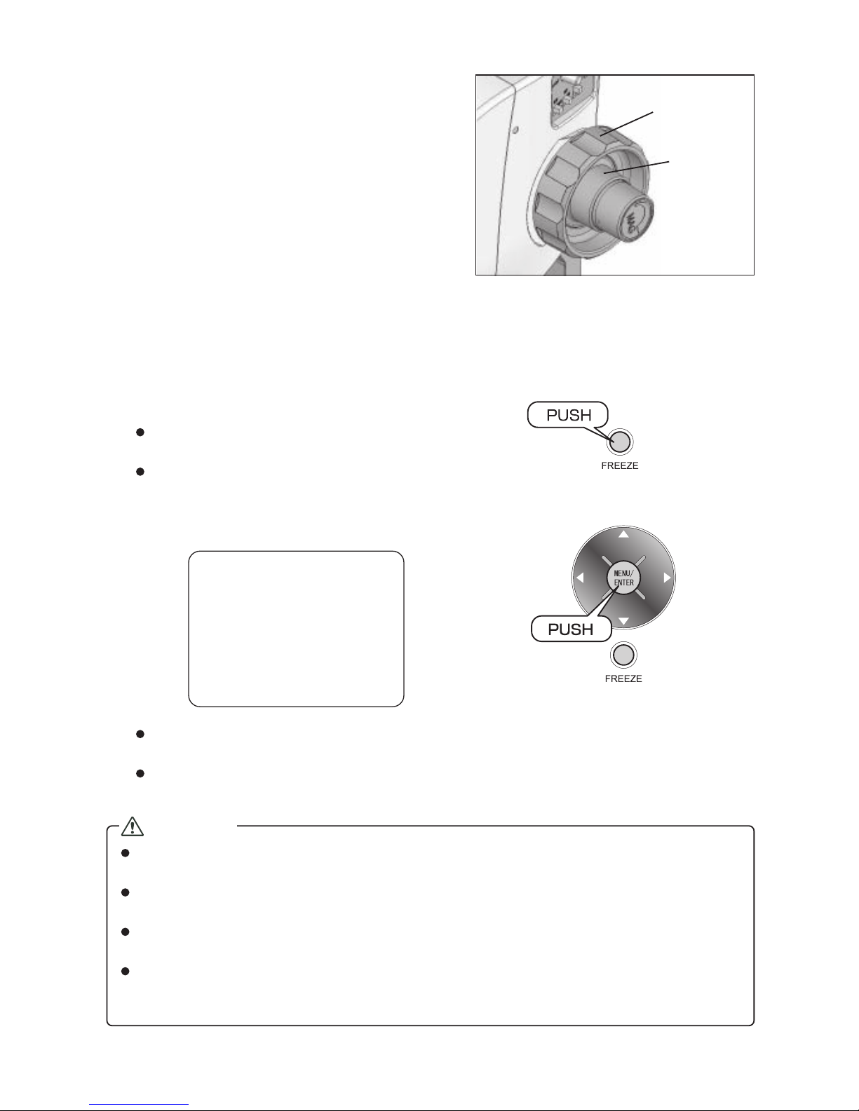
Parts Name and Function ................................. 6
■MSX-500Di .............................................. 6
How to Connect the Cable and Insert
the SD Card........................................................ 8
How to Use MSX-500Di ..................................... 9
■Watching an Image .................................. 9
■Registering an Image ............................ 10
■Reproducing the Registered Image ....... 11
■Reproducing the Registered Image using
a Computer ............................................ 11
■Deleting the Registered Image .............. 12
Adjusting the Light ......................................... 13
■Switching the Light with Mode Button .... 13
■Switching the Light for each Block ......... 14
■Adjusting the Brightness ........................ 14
Setting the MENU ............................................ 15
■Formatting the SD Card ......................... 17
■Using the line generation function ......... 19
■Changing display magnification ............. 22
■List of MENU Screen ............................. 23
■Description of each MENU .................... 24
Maintenance .................................................... 25
Troubleshooting .............................................. 25
Specifications .................................................. 26
■MSX-500Di ............................................ 26
■File Size for One Image ......................... 26
■External View ......................................... 26
Warranty and Servicing .................................. 27
Warranty Card ................................. Back Cover

- 5 -
MSX-500Di
Package Contents
Hexagonal wrench
Viewer and Measurement software
(CD and Instruction Manual)
Instruction Manual (this docu-
ment) with Warranty Card
AC adapter Mini USB cable
(B5 male connector, 5-pin)
Video cable
SD card (256MB)
Optional Parts
Bottom lighting unit
Remote freeze switch
Instruction Manual

- 6 -
Parts Name and Function
■MSX-500Di
11. Magnification Knob
18. White-Black Plate
5. FREEZE Button
4. MENU/ENTER Button
3. Light Switching Button
12. Fine Focus Knob
2. Power Indicator LED
13. Rough Focus Handle
1. LCD
15. VIDEO (NTSC) OUT
Terminal
21. External FREEZE
Input Terminal
20. USB Terminal
17. Power Terminal
19. SD Card Slot
16. Power Switch
14. Lithium Battery Cover
<Camera Controlling Operation Portion>
6. LIGHT Volume
8. SHUTTER
Switch
7. SHUTTER VAR
10. W/B Switch
9. AGC Switch
22. LED Light Portion

- 7 -
1. LCD
Displays an Image
2. Power Indicator LED
Lights when the power is ON.
3. Light Switching Button
Switches the light
4. MENU/ENTER Button
Displays MENU mode, and registers an image.
5. FREEZE Button
Switches LIVE/FREEZE mode
6. LIGHT Volume
Adjusts the brightness of LED light. The light can
be turned off when narrowing down the volume.
7. SHUTTER VAR
(Adjustable shutter speed)
Allows you to adjust the shutter speed (1/10 -
1/1000 seconds) with rotating SHUTTER VAR when
SHETTER switch is set to MANU.
8. SHUTTER Switch (Shutter speed)
MANU: Rotates SHUTTER VAR to adjust the shut-
ter speed.
AE: Adjusts the brightness according to the cap-
turing terms automatically, and sets the ap-
propriate shutter speed.
1/60: Fixes the shutter speed as 1/60 second.
9. AGC Switch (Auto gain control)
ON: Corrects the brightness of the screen when
it is darker.
OFF: Displays the screen without any correction
for the brightness.
10. W/B Switch (White balance)
AUTO: Adjust the white balance automatically ac-
cording to the variety of the color tempera-
ture.
LOCK: Fixes the white balance to maintain the color
temperature
11. Magnification Knob
Adjust the magnification of an object.
12. Fine Focus Knob
Adjust the focus of an object minutely
13. Rough Focus Handle
Adjust the focus of an object widely
14. Lithium Battery Cover
Remove this cover when attaching the optional
Lithium-ion battery pack (for sale in Japan only)
✻Refer to the instruction manual attached with
Lithium-ion battery pack for more detail.
15. VIDEO (NTSC) OUT Terminal
Connects the Video cable.
16. Power Switch
Tu r ns the power ON/OFF.
17. Power Terminal
Connects the AC adapter.
18. White-Black Plate
Set an object on this plate. You can reverse the
white/black surface according to the status of an
object.
19. SD Card Slot
Inserts the SD Card
20. USB Terminal
Connects the USB cable.
21. External FREEZE Input Terminal
Connects the optional Freezing switch.
22. LED Light Portion
Contains the lens and light inside the portion.
NOTE
Do not give a strong impact to the MSX-500Di by dropping or hitting it. The Liquid crystal display is very
delicate especially, so handle it with extreme care. Rough handling may cause the damage of the liquid
crystal display, and malfunction of the main body.

- 8 -
How to Connect the Cable and Insert the SD Card
Be sure to check the power switch is OFF before connecting AC adapter.
✻Refer to the instruction manual for software (separated) for the detail of the connection with USB cable and
computer.
SD card
to AC 100 V
- 240 V
Remote freeze
switch (Option)
TV monitor (NTSC)
USB cable
Video cable
Computer
AC adapter
MSX-500Di
✻Operates in Windows XP SP3 , Windows Vista
SP2 or Windows 7.
Not operating in Windows 2000, ME, 98 or 95.
✻When using a new SD
card, format the SD card
by the MENU function of
the MSX-500Di.
(See page 17)
Lithium-ion
battery pack
(Option for sale
in Japan only)
Image Input terminal
(VIDEO IN)

- 9 -
Magnification
knob
2.5 mm
How to Use MSX-500Di
■Watching an Image
1
Setting an object on the plate, and turn the
power switch ON.
Power indicator LED lights green, and the image
can be displayed on the Liquid crystal display as
live mode.
✻When using Lithium-ion battery pack (DC 7.2 V), the power indicator LED lights blue. The color of the
light changes from blue to orange and then from orange to red according to the battery power condi-
tion, so making it possible to check whether the battery needs charging or not.
2
Rotating the magnification knob to adjust
the magnification
Magnification and the scale can be displayed on the
liquid crystal display.
✻By changing display magnification, zoom display
suitable for the 3.5-inch LCD equipped as standard
can be set. (p. 22)
Magnification Display scale (14 inches)
∞*-
x 20 2.5 millimetre
x 50 1 millimetre
x 100 500 micrometer
x 200 250 micrometer
x 300 167 micrometer
x 400 125 micrometer
x 500 100 micrometer
Display scale
✻If the magnification is not matched with the
capturing distance, the display may be
darker.
* "∞" stands for the capture distance at infinity.
Magnification or display scale, which is displayed
on the liquid crystal display, is a simple scale.
Measure an object directly using a precise scale
etc. if measuring the size of an object precisely.
Shift from lower magnification (∞side) when
adjusting the magnification.
Magnification
Contents on the liquid crystal display

- 10 -
Rough focus
handle
Fine focus
knob
3
Rotating the rough focus handle and the fine
focus knob to adjust the focus
✻See p.13 "Adjusting the Light" for more details of
how to switch the light and adjust the brightness.
■Registering an Image
1
Check the SD card has been inserted.
2
Press FREEZE button.
The image, which is displayed on the liquid crystal dis-
play, can be frozen to enter into the freeze mode.
If the frozen image is different from what you want, press
FREEZE button again to return to the live mode.
3
Press MENU/ENTER button to register the image.
The text "REC" is displayed on the liquid crystal display to save the image in the SD card, and then the
freeze mode turn into the live mode again.
When cancelling the registration, press FREEZE button without pressing MENU/ENTER button.
CAUTION
The time to register ("REC" is displayed) or reproduce may take longer, however do not take the SD card
off during the time. This causes the malfunction of the main body or SD card.
When registering in bitmap format, according to the image size, the time may take for a minute or two at
most.
When the SD card is not inserted, the text " SD card is not inserted" is displayed and an image cannot be
registered. Be sure to insert the SD card (See page 8.)
The file containing magnification information (.mag file), which has the same name as an image file, is
created in an SD card. Be sure to transfer or copy the file with the image file when using the attached
measurement file.
REC

- 11 -
■Reproducing the Registered Image
You can display the registered images on the liquid crystal display. The image is reproduced in the live
mode.
1
Press button in the live mode.
The registered image is displayed on the liquid crystal display.
When registering the multiple images, the newest image is displayed at first, and then press button
to display older images. Meanwhile, the newer images can be displayed with pressing button.
✻When reproducing a bitmap image, according to the image size, the time may take for a minute or two
at most.
2
Press FREEZE button.
Returning to the live mode.
■Reproducing the Registered Image using a Computer
The registered images can be displayed on a computer display if connecting MSX-500Di to a computer
using USB cable.
1
Connect the MSX-500Di to a computer.
2
Press button to select "Mass Storage", and
then MENU/ENTER button.
The registered image is displayed on the computer display.
✻Refer to the instruction manual for software (separated) for the detail of the connection with the MSX-
500Di and computer.
Preview
MassStorage
MSXJ0001.JPGx200
↓DEL 1
Registering
image format
Image total
number
File name of
the image
Magnification

- 12 -
■Deleting the Registered Image
1
Press button in the live mode to display an
image.
The registered image is displayed on the liquid crystal dis-
play.
When registering the multiple images, the newest image
is displayed at first, and then press button to display
older images. Meanwhile, the newer images can be dis-
played with pressing button.
2
Press button, and then MENU/ENTER button.
3
Press button and select "OK".
4
Press MENU/ENTER button.
The image is deleted and, returning to the live mode.
When registering the multiple images, the image, which
has been registered before the deleted one, is displayed.
FREEZE button enables to return to the live mode.
After deleting the only image, the message "No file exists"
displayed, and then returning to the live mode a few sec-
onds later.
MSXJ0001.JPG
CANCEL/OK
↓DEL 1
MSXJ0001.JPG
CANCEL/OK
↓DEL 1

- 13 -
Light switching button Allocation of the LED light
Mode button Spotlight
Adjusting the Light
In MSX-500Di, the mode button enables to switch the light according to an object properly. And MSX-500Di
achieves much finer light switching by turning off the LED light allocated in each block.
Each button supports LED light as follows.
✻The buttons cannot support the spotlights. Mode button can support the spotlights.
■Switching the Light with Mode Button
Press the mode button.
Every time pressing the mode button, the LED light lights as follows.
Lighting Tu r n i ng off
✻When turning the power ON, all the LED lights are lighting.
Light switching button Allocation of the LED light

- 14 -
Light switching button Allocation of
the LED light
LIGHT
volume
■Switching the Light for each Block
The LED lights allocated in each block can be turned off arbitrarily according to an object. Each button
lights up the corresponding block of the LED.
Press the button supporting the light to be
turned off.
The LED light supported by the pressed button can
be turned off.
■Adjusting the Brightness
Rotate the LIGHT volume
The brightness of the light can be adjusted.
✻The light can be turned off when narrowing down
the volume.

- 15 -
Pressing down for more
than 5 seconds
Setting the MENU
In MSX-500Di, various settings can be specified in MENU mode. The following is the procedure to set the
degree of sharpness as an example.
1
Press down the MENU/ENTER button for 5
seconds or longer.
MENU mode (1/6 screen) is displayed.
✻If stopping pressing down the MENU/ENTER but-
ton before displaying MENU screen, an image is reg-
istered, so press down the MENU/ENTER button
until displaying MENU screen.
2
Press button.
MENU mode (2/6 screen) is displayed.
3
Press MENU/ENTER button.
Sharpness setting screen can be displayed.
Sharpness
disable enable
126
MENU 2/6
Sharpness
BLC
Gamma
WB
MENUEnd
MENU 1/6
Brightness
Contrast
Hue
Saturation
MENUEnd

- 16 -
4
Press or button to adjust the sharpness.
Outlines become unclear when pressing button,
while outlines can be clear when pressing but-
ton.
5
Press MENU/ENTER button.
Sharpness can be specified and the screen returns
to the MENU mode (2/6 screen).
6
Press button.
moves to "MENU End".
can be moved to "MENU End" by pressing but-
ton four times.
7
Press MENU/ENTER button.
Returning to the live mode.
Sharpness
disable enable
140
MENU 2/6
Sharpness
BLC
Gamma
WB
MENUEnd
MENU 2/6
Sharpness
BLC
Gamma
WB
MENUEnd

- 17 -
Pressing down for more
than 5 seconds
■Formatting the SD Card
This section describes the procedure to format an SD card with the MENU function of MSX-500Di.
1
Insert an SD card into the SD card slot.
2
Press down the MENU/ENTER button for 5
seconds or longer.
MENU mode (1/6 screen) is displayed.
3
Press button twice.
MENU mode (5/6 screen) is displayed.
5/6 screen can be displayed by pressing button
four times.
4
Press button.
moves to "SD Format".
MENU 1/6
Brightness
Contrast
Hue
Saturation
MENUEnd
MENU 5/6
Char.display
SDFormat
Zoomdisplay
Ver.info
MENUEnd
MENU 5/6
Char.display
SDFormat
Zoomdisplay
Ver.info
MENUEnd

- 18 -
5
Press MENU/ENTER button.
SD Format setting screen will be displayed.
6
Press button.
moves to "Yes".
7
Press MENU/ENTER button.
The SD card has been formatted and the screen
returns to the MENU mode (as shown in step 4 of
page 17).
8
Select "MENU End" with / button to end
the MENU mode.
CAUTION
Available format type of the SD card is FAT16. If formatting an SD card using MENU mode, the format
type is FAT16. Check the format type of the SD card formatted by a computer. Wrong format type is not
acceptable.
SDFormat
Yes
No
SDFormat
Yes
No
MENU 5/6
Char.display
SDFormat
Zoomdisplay
Ver.info
MENUEnd

- 19 -
■Using the line generation function
1
Select the line to use.
2
Description of available lines
2-1
Cross Line
Displays a cross line starting from the center of the
screen.
This scale uses the same scale unit as the display
scale shown at the lower right when magnification
is displayed.
2-2 Grid
Displays grids on the screen.
These grids use the 1/2 scale unit compared to the
display scale shown at the lower right when magni-
fication is displayed.
Line
CrossLine
Grid
#Line
OFF

- 20 -
2-3
# Line
LIVE
x
500
400
300
200
100
50
20
∞
30 0 JPEG L
1.67
mm
Displays # Line on the screen.
Each of the 4 lines which consist of # Line can be
moved in parallel.
2-4
How to move # Line
qq
qq
qPress FREEZE button.
Lines can be moved by making the screen motion-
less.
ww
ww
wLine A, B, C and D can be moved by pressing
an arrow assigned to each on the cross key
button.
✻Image when Line A is moved.
After pressing FREEZE button, lines can be moved
by pressing up, down, left or right arrows on the cross
key button.
A
B
CD
Table of contents