manuals.online logo
Brands
  1. Home
  2. •
  3. Brands
  4. •
  5. Morningstar
  6. •
  7. Controllers
  8. •
  9. Morningstar SunLight-10 User manual

Morningstar SunLight-10 User manual

Quick Start Guide
14
Specifications:
Battery Type Selection:
System Voltage
Maximum Voltage
Rated Solar Input
Rated Load
© 2023 Morningstar Corporation. All Rights Reserved. MS-004021 Rev 1
In the Box:
Tools Required:
— 3/16" (5 mm) Flathead Screwdriver
— #2 Phillips Screwdriver
— Multimeter
Important Safety Information:
Scan QR Code to go
directly to the
SunLight Operator’s
Manual and warranty
information online.
Contact Information:
Technical Support: morningstarcorp.com/support
Phone: 1-215-321-4457
OR
Warranty Registration:
https://www.morningstarcorp.com/product-registration/
Battery Select
Jumper INSERTED
Battery Select
Jumper
REMOVED
SOLAR LIGHTING CONTROLLER
SL-10L-12V
10 A
10 A
SS-20L-12V
20 A
20 A
30 V 50 V
12 V 24 V12 V 24 V
30 V 50 V
For Sealed Batteries: For Flooded Batteries:
IMPORTANT:
The SunLight charging algorithm is compatible with lead-acid or NiCd batteries. NiMH, Li-ion,
and other battery chemistries are not compatible with the SunLight charging algorithm.
SL-10L-12V
SL-20L-12V
SL-10L-24V
SL-20L-24V
SUNLIGHT Models:
SunLight-10
Solar Lighting Controller
SunLight-20
Solar Lighting Controller
SunLight-10
Solar Lighting Controller
SunLight-20
Solar Lighting Controller
SL-10L-24V SS-20L-24V
Temperature Compensation -27 mV/°C -54 mV/°C -27 mV/°C -54 mV/°C
Regulation Voltage: Sealed PWM 14.1 28.2 14.1 28.2
Regulation Voltage: Flooded PWM 14.4 28.8 14.4 28.8
Low-Voltage Disconnect (LVD) 11.7 V 23.4 V11.7 V 23.4 V
Low-Voltage Reconnect (LVR) 12.8 V 25.6 V12.8 V 25.6 V
Self-consumption 8 mA 9 mA8 mA 9 mA
Ambient Temperature Range -40 to 60°C
25% Current Overload 5 minutes N/A5 minutes N/A
OFF
2 hours ON
4 Hours ON
6 Hours ON
8 Hours ON
3 / OFF / 1
4 / OFF / 2
6 / OFF / 2
Sunset Sunrise
Night
Dusk-to-Dawn
10 Hours ON
LIGHTING CONTROL
D/D
6/2
4/2
3/1 10
8
6
4
2
OFF
Turn the dial to the
desired setting. This
illustration shows the
dial set to OFF.
Lighting Control Options:
See the SunLight Operator’s Manual for detailed
information on lighting control settings.
WARNING: Shock Hazard
The SunLight solar lighting controller must
be installed by a qualified technician in
accordance with the electrical regulations
of the country of installation.
IMPORTANT: READ the SunLight
Operator’s Manual for safety and
regulatory information, instructions on
configuration and operation, and
warranty information.
32
SunLight Solar Lighting Controller
Quick Start Guide
(+)
(–)
(+) (–)
Solar Disconnect*
Photovoltaic (PV) Array
Battery / Battery Bank
Fuse*
Power UP Sequence:
1. Connect Battery/Battery Bank.
2. Connect Solar.
Power DOWN Sequence:
1. Disconnect Solar.
2. Disconnect Battery/Battery Bank.
Mounting:
Recommended Minimum Clearance:
CAUTION: Equipment Damage
Do not expose the SunLight CC to weather.
Locate in a dry, protected area to prevent
equipment damage. Ensure the minimum
clearance requirements are followed to
provide adequate ventilation and prevent the
unit from overheating.
IMPORTANT: Example only. Actual wiring may vary.
READ the SunLight Operator’s Manual for mandatory
safety requirements. All configurations must comply
with local and national electric codes. Consult your local
electric authority to ensure compliance.
See the Morningstar PV String Calculator at:
http://string-calculator.morningstarcorp.com/
Component Wire Size
(Solid)
#10 AWG
5.2 mm2
(Maximum)
Tool Required
3/16" (5 mm)
Flathead or
#2 Phillips Screwdriver
WIRING AND TORQUE REQUIREMENTS
Torque
(Maximum)
10.6 in-lbs.
(1.2 Nm)
Securing
hardware
not shown.
WARNING: Explosion Hazard
Never install the SunLight in an enclosure with
vented/flooded batteries. Battery fumes are
flammable and will corrode and destroy the
SunLight circuits. Ensure sufficient ventilation.
Battery (+) Battery (—)
Wire Size
(multistrand)
#10 AWG
5.2 mm2
(Maximum)
Wire Size
(fine strand)
#10 AWG
5.2 mm2
(Maximum)
Recommended
Order of
Installation
Lighting:
Primary System
Ground
1
2" (51 mm)
Fuses, Breakers, or Disconnects
*The sizing of fuses, breakers, or disconnects must be based on required wire
ampacity. Do NOT close breakers or disconnects, or insert fuses in the fuse-
holder, until after all wiring has been completed.
(+)
(–)
12 Vdc Module 12 Vdc Module
30 Voc Max @ 12 V battery /
50 Voc @ 24 V battery
Charging
LED
WARNING: Shock Hazard
Fuses, circuit breakers, and disconnect
switches should never open grounded
system conductors. Only GFDI devices
are permitted to disconnect grounded
conductors.
WARNING: Shock Hazard
Test between all terminals and ground
before touching.
Power or accessory terminals are NOT
electrically isolated from DC input and
may be energized with hazardous
solar voltage.
IMPORTANT:
Ensure there is only 1 DC Negative-to-
Ground Bond in the entire system.
2" (51 mm)
(12-volt or 24-volt**)
**SunLight Model Dependent
WARNING: Shock Hazard
The solar PV array can produce open-circuit
voltages in excess of 40 Vdc when in sunlight.
Verify that the solar input breaker or
disconnect has been opened (disconnected)
before installing the system wires.
PV (+)
PV (–)
Load (+)
Load (–)
Battery
Disconnect*
Low-Voltage
Disconnect (LVD)
LED
2
3
4
5
6
Load Terminals
Battery Terminals
Solar Terminals
12
3 4
5 6
NOTE: Fork-terminal connectors are not required. Use only copper wire with minimum 75°C
insulation rating and between 10 AWG (5.2 mm2) and 14 AWG (2.1 mm2) gage.
IMPORTANT:
Array voltage should NEVER exceed the maximum
input voltage.
Lighting
Control Switch
Test Button
For additional information
about the LED indications or the
TEST Button functions, see the
SunLight Operator’s Manual.
WARNING: Risk of Fire
All over-current protection devices and
wiring must be sized properly.
Step 1: Choose Mounting Location
Locate the SunLight on a vertical surface within
10 feet (3 m) of the battery bank that is protected
from direct sun, high temperatures, and water.
Step 2: Check for Clearance and Ventilation
Place the SunLight in the location where it will be
mounted. Verify that there is sufficient room to
run wires and that there is ample room above and
below the controller for air flow.
Step 3: Mount the Controller
Mark and drill holes as needed, or use self-tapping
screws, and secure the controller in place.
*See "Fuses, Breakers or
Disconnects" in the Wiring
and Torque Table below.
LEGEND
Negative (–)
Positive (+)
Ground
This manual suits for next models

5

Other Morningstar Controllers manuals

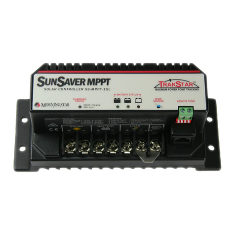
Morningstar TriStar TS-60 User manual

Morningstar

Morningstar TriStar TS-60 User manual

Morningstar Sunlight SL-10 User manual

Morningstar

Morningstar Sunlight SL-10 User manual

Morningstar SUNSAVER DUO User manual

Morningstar

Morningstar SUNSAVER DUO User manual

Morningstar ProStar-15 User manual

Morningstar

Morningstar ProStar-15 User manual

Morningstar ProStar MPPT Series User manual

Morningstar

Morningstar ProStar MPPT Series User manual

Morningstar ProStar PS-15 User manual

Morningstar

Morningstar ProStar PS-15 User manual

Morningstar TriStar Professional TS-60M User manual

Morningstar

Morningstar TriStar Professional TS-60M User manual

Morningstar SUNSAVER DUO User manual

Morningstar

Morningstar SUNSAVER DUO User manual

Morningstar TRISTAR TS-MPPT-60-600V-48-DB User manual

Morningstar

Morningstar TRISTAR TS-MPPT-60-600V-48-DB User manual

Morningstar SunSaver SS-6 User manual

Morningstar

Morningstar SunSaver SS-6 User manual

Morningstar ProStar MPPT TRAKSTAR PS-MPPT-15 User manual

Morningstar

Morningstar ProStar MPPT TRAKSTAR PS-MPPT-15 User manual

Morningstar GenStar GS-MPPT-60 User manual

Morningstar

Morningstar GenStar GS-MPPT-60 User manual

Morningstar SunSaver MPPT Meter Map User manual

Morningstar

Morningstar SunSaver MPPT Meter Map User manual

Morningstar ESSENTIAL Series User manual

Morningstar

Morningstar ESSENTIAL Series User manual

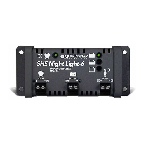
Morningstar SHS-6 User manual

Morningstar

Morningstar SHS-6 User manual

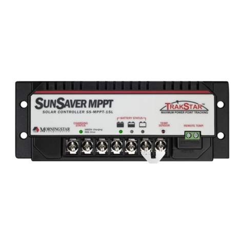
Morningstar SUNSAVER MPPT SS-MPPT-15L User manual

Morningstar

Morningstar SUNSAVER MPPT SS-MPPT-15L User manual

Morningstar SUNSAVER MPPT SS-MPPT-15L User manual

Morningstar

Morningstar SUNSAVER MPPT SS-MPPT-15L User manual

Morningstar TriStar TS-MPPT-30 User manual

Morningstar

Morningstar TriStar TS-MPPT-30 User manual

Morningstar EC-10 General instructions

Morningstar

Morningstar EC-10 General instructions

Morningstar TriStar TS-60M User manual

Morningstar

Morningstar TriStar TS-60M User manual

Morningstar MC6 MkII User manual

Morningstar

Morningstar MC6 MkII User manual

Morningstar ProStar MPPT Series User manual

Morningstar

Morningstar ProStar MPPT Series User manual

Morningstar SunSaver Duo SSD-25RM User manual

Morningstar

Morningstar SunSaver Duo SSD-25RM User manual

Morningstar PROSTAR-12 User manual

Morningstar

Morningstar PROSTAR-12 User manual

Popular Controllers manuals by other brands

AMX Axcent3 pro Schematics document

AMX

AMX Axcent3 pro Schematics document

DIGM Technology GSM-0308WPC user manual

DIGM Technology

DIGM Technology GSM-0308WPC user manual

Turnigy Dlux user manual

Turnigy

Turnigy Dlux user manual

Grundfos Vaccuperm VGA-146 Installation and operating instructions

Grundfos

Grundfos Vaccuperm VGA-146 Installation and operating instructions

Allen-Bradley PowerFlex 700S quick start

Allen-Bradley

Allen-Bradley PowerFlex 700S quick start

Vimar by-me Eikon 20527 quick start guide

Vimar

Vimar by-me Eikon 20527 quick start guide

Burkert Type 3003 quick start

Burkert

Burkert Type 3003 quick start

Saga SAGA1-T Series user manual

Saga

Saga SAGA1-T Series user manual

Blueprint Controllers BCDCC-1 manual

Blueprint Controllers

Blueprint Controllers BCDCC-1 manual

Zennio MAXinBOX 24 Technical documentation

Zennio

Zennio MAXinBOX 24 Technical documentation

Evco EV9376 manual

Evco

Evco EV9376 manual

Kleemann GENIUS20 manual

Kleemann

Kleemann GENIUS20 manual

Trio MC664 Quick connection guide

Trio

Trio MC664 Quick connection guide

Klinkmann Unitronics Vision V230 BATTERY REPLACEMENT INSTRUCTIONS

Klinkmann

Klinkmann Unitronics Vision V230 BATTERY REPLACEMENT INSTRUCTIONS

Tusa RS-790 owner's manual

Tusa

Tusa RS-790 owner's manual

Eliwell ID 985 manual

Eliwell

Eliwell ID 985 manual

Mitsubishi Electric MELSEC iQ-R Series Programming manual

Mitsubishi Electric

Mitsubishi Electric MELSEC iQ-R Series Programming manual

Providence PEC-4V owner's manual

Providence

Providence PEC-4V owner's manual

manuals.online logo
manuals.online logoBrands
  • About & Mission
  • Contact us
  • Privacy Policy
  • Terms and Conditions

Copyright 2025 Manuals.Online. All Rights Reserved.