1 3
2
2
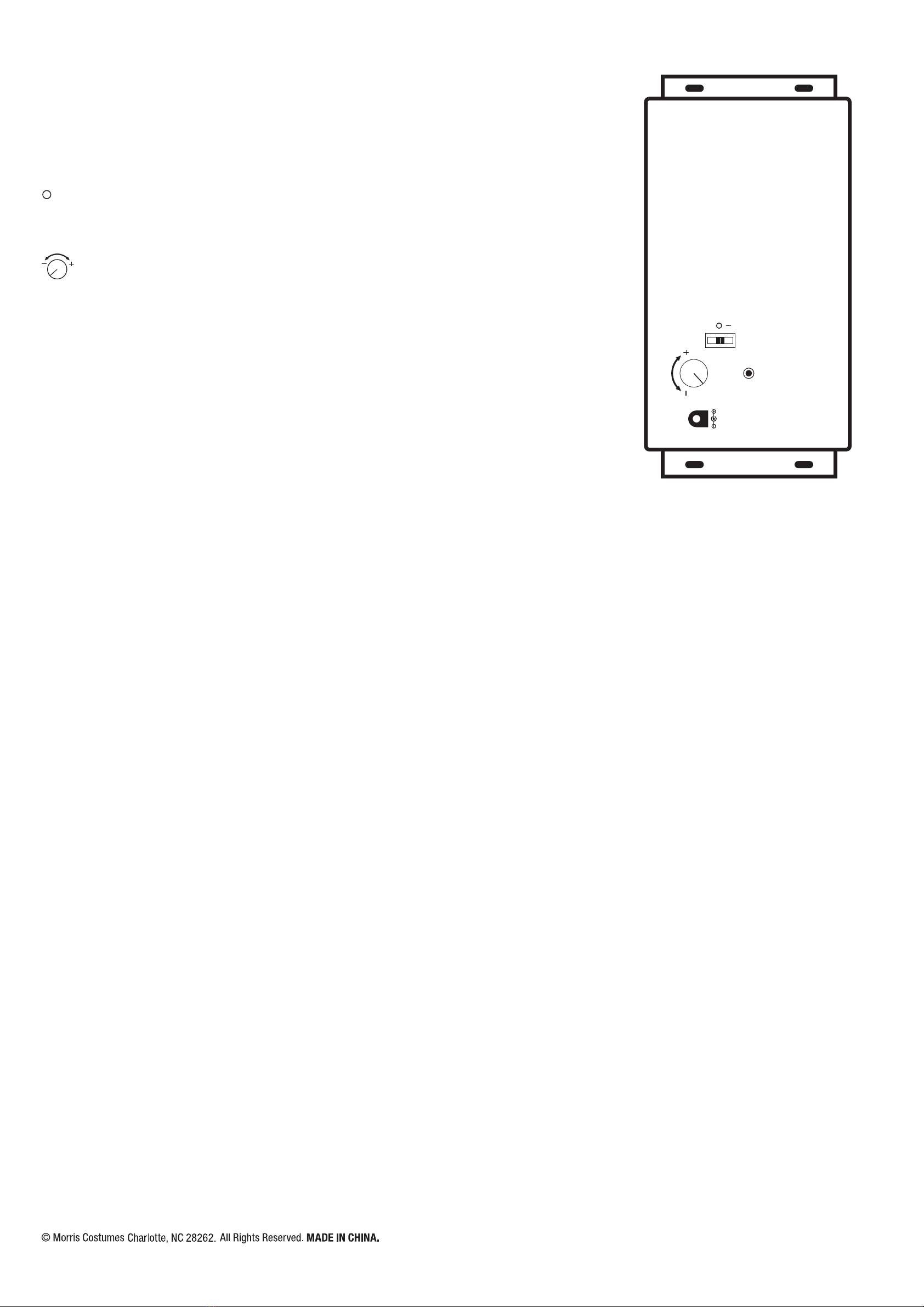
Note: Do not plug the Power Adapter into
power outlet until item assembly is
completed.
OPTIONAL: If you choose to use the Step
Activation Pad, plug the connector into the
input receiving jack marked “TRY ME” on
the Function Control Box and set the Step
pad in front of the character when ready to
display.
Sensor / Détecteur
5.9 V
STEP
HERE
ADAPTER
(Included)
Try me / Essaie-moi / Pruébame
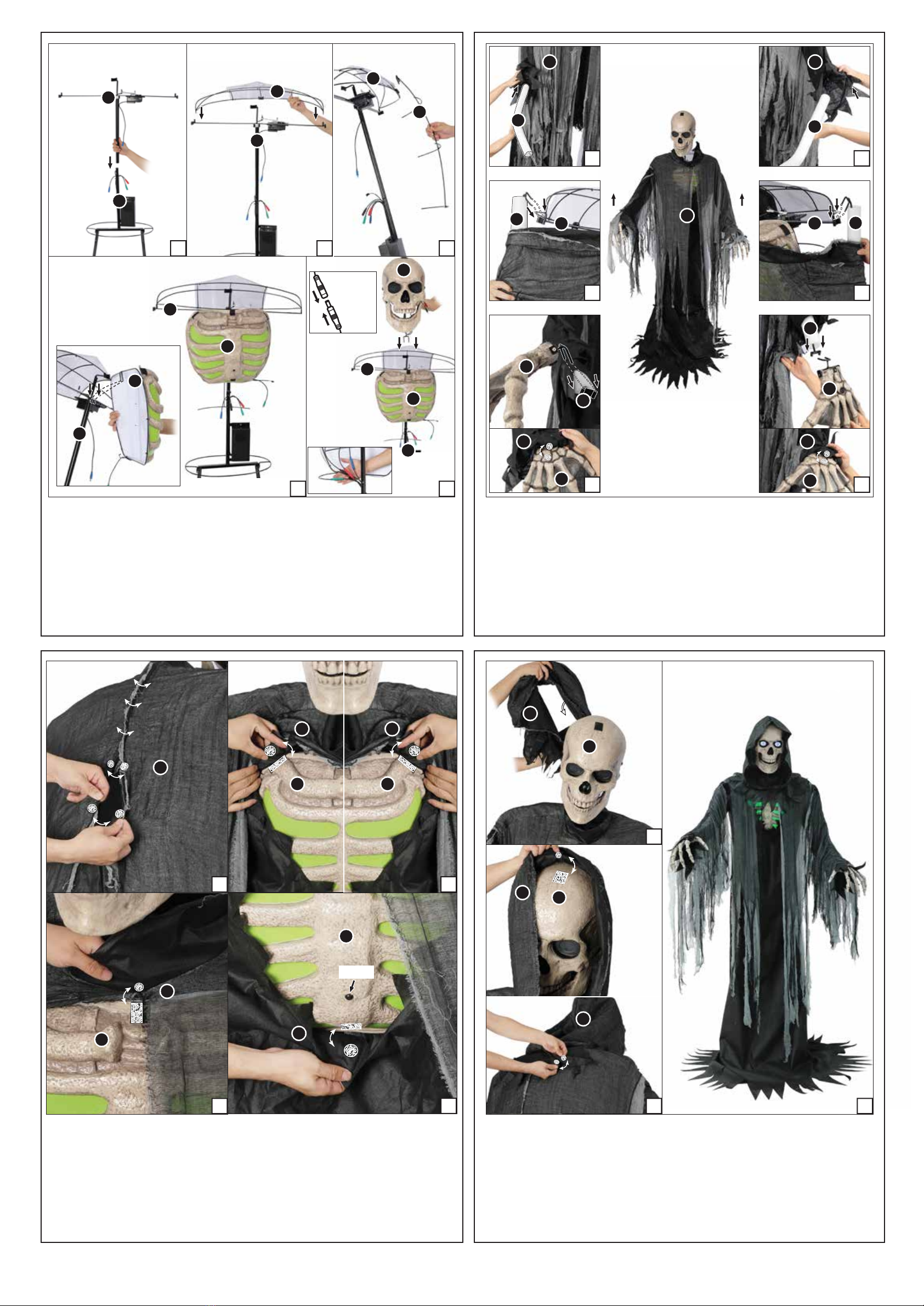
STEP 2
Lower the (D) Costume over the assembled (B,C) Support Poles as shown in Figure 1.
NOTE: The speaker on the Function Control Box located on the (E) Torso Frame should be facing front.
Assemble the (E) Torso Frame to the (C) Upper Support Poles and secure by aligning the quick
connect push buttons into the pre-drilled holes as shown in Figure 2.
Lower the (F) Hip Hoop down over the (E) Torso Frame and slide through the slots located on the
bottom of the (E) Torso Frame as shown in Figure 3.
Now, plug the Adapter into the input receiving jack marked “DC 5.9V” on the Function Control Box
and route the Power Adapter down and out the bottom of the item.
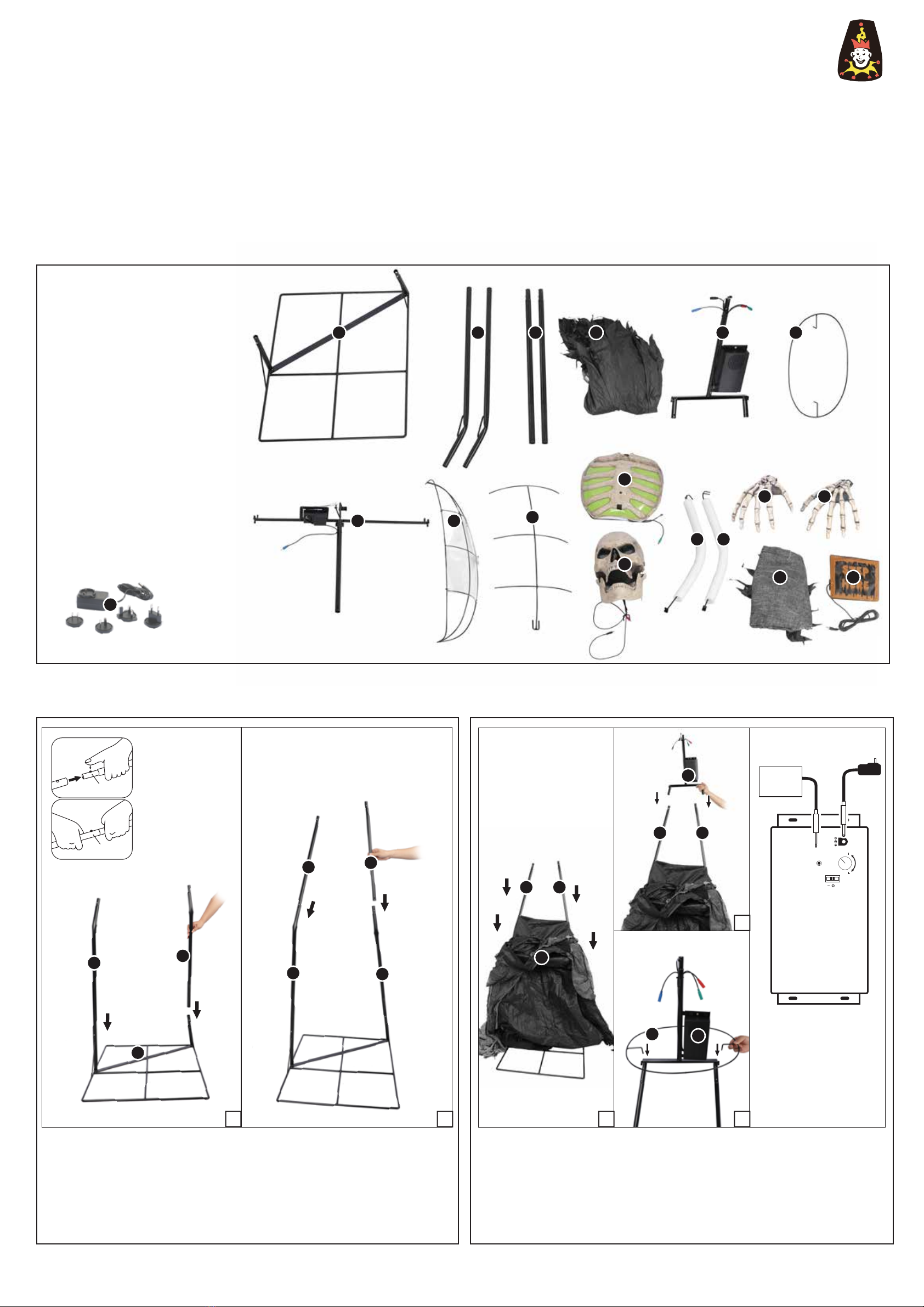
PARTS LIST
A. Base x 1
B. Lower Support Poles x 2
C. Upper Support Poles x 2
D. Costume x 1
E. Torso Frame x 1
F. Hip Hoop x 1
G. Upper Torso Frame x 1
H. Shoulder Frame x 1
I. Spinal Frame x 1
J. Chest x 1
K. Head x 1
L. Right Arm x 1
M. Left Arm x 1
N. Right Hand x 1
O. Left Hand x 1
P. Hood x 1
Q. Step Pad x 1
R. Universal Adapter (Included) x 1
Input: 100 - 240VAC 50/60Hz
Output: 5.9V 3.0A
1
Means It's
Locked
Click
Locking Pin
BEFORE ASSEMBLING, REMOVE ALL THE ABOVE PARTS FROM BOX. IF ANY PART IS MISSING, PLEASE CONTACT CUSTOMER SERVICE AT
SUPPORT@MORRISCOSTUMES.COM, OR BY PHONE 704-332-3304. IN YOUR EMAIL INQUIRY, PLEASE INCLUDE: YOUR ORDER NUMBER, WHO YOU BOUGHT IT FROM,
AND WHAT SPECIFICALLY IS WRONG. THANK YOU.
1/3
EASY ASSEMBLY AND OPERATION INSTRUCTIONS
MR-124885 Towering Reaper
Please follow the step by step guide and enjoy your
Towering Reaper!
WARNING
This item is not a toy and should be used for decoration only. This item contains small parts that can be a choking
hazard. Keep all plastic and wire parts away from children.
1. Please use the adapter supplied by manufacturer.
2. Please assemble item according to instructions. Connect all wires according to matching color.
3. Children should be supervised by adults. Item should not be grabbed, as it becomes a tipping
hazard. Keep all away from the adapter, as it heats up during operation.
Please read all instructions carefully before assembling. Save this instruction sheet for future reference.
CARE AND STORAGE INSTRUCTIONS
For best performance operate your item indoors. When not in use, store this product in its
original packing. Keep away from heat and moisture.
A
A
BB
BB
F
E
E
C
C
C C
C
C
D
I
R
J
K
L M
QP
NO
B C D E F
G H
STEP 1
Note: Throughout the instructions, left and Right are relative to the character. A Ladder is
recommended for assembly. Two person assembly is recommended.
Attach the (B) Lower Support Poles to the (A) Base and secure by aligning the quick connect push
buttons into the pre-drilled holes as shown in Figure 1.
Attach the (C) Upper Support Poles to the (B) Lower Support Poles and secure by aligning the
quick-connect push buttons into the pre-drilled holes as shown in Figure 2.
Front
Back
Right Left