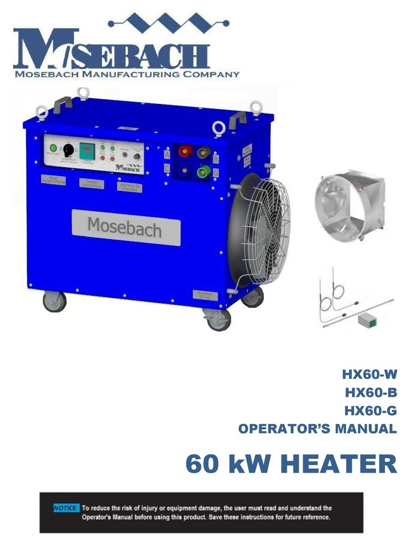
Mosebach HX150 User manual

HX150
OPERATOR’S MANUAL
150 kW HEATER

2
Table of Contents
RECEIVING ........................................................................................................................................... 3
INSPECTING ........................................................................................................................................... 3
LIFTING AND MOVING ......................................................................................................................... 3
SAFETY SYMBOLS ................................................................................................................................. 4
SYMBOL MEANING ............................................................................................................................... 4
SAFETY .................................................................................................................................................. 5
DEFINITIONS........................................................................................................................................... 6
OWER AND GROUND CONNECTIONS ............................................................................................. 7
AIR INTAKES AND EXHAUST ORTS ..................................................................................................... 7
INTAKE AND EXHAUST DUCTING ......................................................................................................... 8
EXHAUST TEM ERATURE ........................................................................................................................ 9
CONNECTING AND DISCONNECTING ............................................................................................... 9
S ECIFICATIONS .................................................................................................................................. 9
O ERATION ........................................................................................................................................ 10
RE-STARTU ........................................................................................................................................ 10
STARTU AND O ERATION ................................................................................................................. 10
REMOTE O ERATION........................................................................................................................... 11
SHUTDOWN .......................................................................................................................................... 12
TROUBLESHOOTING ........................................................................................................................... 12
RE LACING FUSES .............................................................................................................................. 13
RE LACING RESISTORS ...................................................................................................................... 14
REVENTATIVE MAINTENANCE OF HEATER ...................................................................................... 14
O TIONAL EQUI MENT ...................................................................................................................... 15
SERVICE ARTS ................................................................................................................................... 16
A ENDIX A – ELECTRICAL SCHEMATICS .............................................................................................

3
READ ALL INSTUCTIONS!
WARNING: This uni opera es wi h high vol age and has he abili y o produce ex reme
empera ures. Failure o follow all ins ruc ions shown in his manual may resul
in serious injury or dea h.
RECEIVING
INSPECTING
1. Check he ex erior of he shipping con ainer or packaging ma erial for obvious
damage.
2. Documen and repor any ex erior damage o he carrier immedia ely.
3. Check if cas ers urn freely and ha locks work.
LIFTING AND MOVING
CAUTION: Use proper lif ing devices or me hods. Inadequa e lif ing devices or me hods
can damage he hea er.
Fork
Channels
1

4
SAFETY SYMBOLS
The purpose of safe y symbols is o a rac your a en ion o possible dangers. The safe y
symbols and he explana ions wi h hem deserve your careful a en ion and unders anding.
The symbol warnings do no , by hemselves, elimina e any danger. The ins ruc ions and
warnings hey give are no subs i u es for proper acciden preven ion measures.
WARNING: Be sure o read and unders and all safe y ins ruc ions in he Opera or’s
Manual, including all safe y aler symbols such as “DANGER,” “WARNING”,
and “CAUTION” before using his uni .
SYMBOL MEANING
DANGER
Indica es a hazardous si ua ion ha , if no avoided,
will resul in dea h or serious injury. This symbol is
limi ed o he mos ex reme si ua ions.
WARNING
Indica es a hazardous si ua ion ha , if no avoided,
could resul in dea h or serious injury.
CAUTION
Indica es a hazardous si ua ion ha , if no avoided,
could resul in minor or modera e injury.
NOTICE Indica es a si ua ion ha , if no avoided, could
resul in misuse of or damage o he load bank.
NOTICE - Wear
Eye rotection
Always wear safe y goggles or safe y glasses when
opera ing his uni .
NOTICE - Read
Operator’s
Manual
To reduce risk of injury, read and unders and en ire
opera or’s manual before opera ing uni .
NOTICE - Let
Fans Run
Le fans run for a leas 3 minu es af er urning off
es power before urning fans off.
NOTICE - Do
Not Block
Airflow
Uni may overhea wi hou proper airflow

5
CAUTION –
Blown Debris
To reduce risk of injury o persons or damage o he
uni , remove objec s ha can be moved by he
cooling fans of he uni .
WARNING –
Electrical
Shock
This uni can po en ially opera e a high vol age
and curren . Improper use can lead o
elec rocu ion, causing serious injury or dea h.
CAUTION –
Burn and fire
hazard
Exhaus air and surfaces may be ho
CAUTION –
Moving arts
Moving par s can cu or crush. Keep hands clear.
Do no opera e wi h guards removed.
SAFETY
WARNING: This hea er is designed o handle only one specified vol age. Work on hea er
in ernal sys ems should only be a emp ed by highly- rained echnicians and
only when power has been disconnec ed and canno be reconnec ed o he
uni .
CAUTION: Hea ers mus be ins alled and used in accordance wi h local codes. Cables
mus be able o safely handle he vol ages and curren expec ed. Size cables
for a vol age drop of 2% or less. Insula ion on he cabling mus be sui able for
he condi ions ha he cables will be subjec ed o.
NOTICE: IMPORTANT INSTRUCTIONS
When using elec rical appliances, basic precau ions should always be followed o reduce
he risk of fire, elec rical shock, and injury o persons, including he following:
1. Read all ins ruc ions before using his hea er.
2. This hea er is ho when in use. To avoid burns, do no le bare skin ouch ho
surfaces. Use handles when moving his load bank. Keep combus ible ma erials,
such as furni ure, pillows, bedding, papers, clo hes, and cur ains a leas 20 fee
from all sides of he hea er

6
3. Ex reme cau ion is necessary when any hea er is used by or near children or
invalids and whenever he hea er is lef opera ing and una ended.
4. Always unplug hea er when no in use.
5. Do no opera e any hea er wi h a damaged cord or plug or af er he hea er
malfunc ions or has been dropped or damaged in any manner. Discard hea er
or re urn o au horized service facili y for examina ion and/or repair.
6. Do no run cord under carpe ing. Do no cover cord wi h hrow rugs, runners, or
similar coverings. Do no rou e cord under furni ure or appliances. Arrange cord
away from raffic areas and where i will no be ripped over.
7. Connec o properly grounded ou le s only.
8. Do no inser or allow foreign objec s o en er any ven ila ion or exhaus opening
as his may cause an elec ric shock or fire, or damage he hea er.
9. To preven a possible fire, do no block air in akes or exhaus in any manner. Do
no use on sof surfaces, like a bed, where openings may become blocked.
10. The hea er has ho par s inside. Do no use i in areas where gasoline, pain , or
flammable liquids are used or s ored.
11. Use his hea er only as described in his manual. Any o her use no
recommended by he manufac urer may cause fire, elec ric shock, or injury o
persons.
12. Always plug hea ers direc ly in o a wall ou le /recep acle. Never use wi h a re-
loca able power ap (ou le /power s rip).
13. “SAVE THESE INSTRUCTIONS”
DEFINITIONS
VAC Volt Al erna ing Curren Vol age
A
Amperes Curren
kW Kilowatt Power
Min Minutes Time
Sec Seconds Time
CFM Cubic Feet per
Minute Volume ric Air Flow
F M Feet per
Minute Air Speed

7
OWER AND GROUND CONNECTIONS
WARNING: ELECTRIC SHOCK HAZARD. All power connec ions mus be connec ed or
covered. Failure o do so will expose opera ors o possible shock and he
possibili y of grounding-ou or shor ing-ou of he es power source.
All power connec ions mus be covered or connec ed. Failure o do so will allow applied
vol ages o be presen on exposed me al par s of he connec ors. Opera ors could receive
an elec rical shock if hey come in con ac wi h hese exposed conduc ors. If a loose
conduc or con ac s an exposed me al par of a “ho ” recep acle, i could lead o rounding-
ou or shor ing-ou of he source genera or.
WARNING: ELECTRIC SHOCK HAZARD. The grounding lug mus be connec ed o ear h
ground. Opera ing wi hou a grounding connec ion could lead o injury or
dea h.
When he Hea er is in opera ion he grounding cam mus be firmly and elec rically
connec ed o ear h ground. Failure o do so could allow deadly vol age o be presen on
he surface of he enclosure. The grounding connec ion provides a low resis ance pa h o
ground. This grounding pro ec s he opera or from he possibili y of elec rical shock.
AIR INTAKES AND EXHAUST ORTS
CAUTION: All air in akes and exhaus por s mus be clear and fully open. Each Hea er
has one or more air in akes designed for proper air flow. Reducing or blocking
air flow will lead o overhea ing and Hea er failure.
Cus omer Cam-Lock
Connec ions
Ground
Cam
2

8
High volumes of cooling air are needed o preven load elemen s from overhea ing. By heir
very na ure, resis ors under load change elec rical energy o hea . This hea mus be
removed from he uni . The fans, in ake, and exhaus por s are sized o provide he proper
amoun of cooling air. Preven ing or limi ing air flow will allow he Hea er o overhea .
Keep in ake a leas four fee away from walls and obs ruc ions.
NOTICE: To increase he life of he load elemen s, allow he fans o run a leas 3 minu es
af er he load is removed or un il exhaus air is cool.
CAUTION: Good air flow keeps he Hea er cool bu can very easily move ligh debris
such as paper, cardboard, and dus wi h grea veloci y. Loose ma erials
around he Hea er, especially near he in ake and exhaus , mus be secured
o preven movemen . Ma erial on he exhaus side may be blown in o and
injure a bys ander. Ma erial near he in ake may be aken in o he Hea er
damaging in ernal componen s.
INTAKE AND EXHAUST DUCTING
NOTICE: Duc ing will cause some air flow reduc ion. Incorrec duc ing can severely reduce
air flow o he hea ing elemen s. Severe reduc ion in air flow will lead o hea er
failure.
Some impor an considera ions when ins alling duc ing wi h your hea er:
Only use duc ing ha can connec o he in ake or exhaus adap ers designed by
Mosebach Manufac uring. O her adap er designs may allow you o connec
incorrec ly sized duc ing which may resul in hea er failure.
Use duc ing wi h a 20” diame er ha can be a ached o he adap ers supplied by
Mosebach Manufac uring.
Keep he duc ing as s raigh as possible. If bends are required, ensure he bend radius
is larger han 40”.
NOTICE: All duc ing should be secured. Unsecured duc ing on he in ake end may
collapse, reduce air flow and cause he hea er o fail. Unsecured duc ing on
he exhaus may move o an undesired loca ion and cause damage.
Use no more han 50’ of duc ing.

9
EXHAUST TEM ERATURE
WARNING: FIRE AND BURN HAZARD. Keep flammable ma erial a leas 40 fee away from
he Hea er. A grea deal of hea is expelled from he Hea er. Tempera ures
inside he Hea er are sufficien o igni e flammable fumes or ma erials. Failure
o main ain proper housekeeping and properly securing flammable ma erial
could lead o fire, burns, and/or injury.
Even wi h sufficien air flow, in ernal componen empera ure will exceed 400 degrees F. Air
and ma erial several fee from he Hea er can be hea ed o empera ures in excess of 150
degrees F. Flammable ma erials mus no be kep around he Hea er. Hea from he Hea er
could igni e his ma erial.
Flammable fumes or ma erial such as paper could be drawn in o he Hea er, igni ed, and
expelled from he exhaus por . Opera ors s anding on he exhaus side of he Hea er may
be exposed o high empera ures or possibly burning ma erials. Unless proper housekeeping
is prac iced in he vicini y of he Hea er while i is in opera ion, fire could resul .
CONNECTING AND DISCONNECTING
WARNING: BURN HAZARD. A emp ing o connec or disconnec leads while Hea er is in
opera ion can lead o injury or dea h. Connec ing or disconnec ing plugs and
recep acles while curren is flowing or vol age is presen may cause and
elec rical arc.
Before making or breaking any connec ions o he hea er, i should be confirmed ha he
source is de-energized and no vol age or curren is presen .
S ECIFICATIONS
Cooling Fan 480VAC, 3 phase, 60Hz, 5.0 HP, 6500 CFM
Control Power 1 0VAC, 1 phase, 60 Hz from step down transformer
Rating Continuous duty
Power Factor 1.0
Load Elements The current at each step is subject to a manufacturing tolerance of ±5%.
Enclosure
Light-weight metal enclosure with casters for easy maneuvering.
Electro-statically painted powder coat, Blue: PPG PCTZ50108
Touch up paint is Pantone 80-c color. Plastikote custom color universal blend.
Air inlet and outlet are covered by metal screens.
Heat is discharged horizontally.

10
Optional
Equipment
0” flexible duct.
Exhaust and Intake duct transitions for 0” flexible duct.
Wired remote temperature control with thermistor ports.
Unit Weight 450 lbs.
Outer-Most
Dimensions
57 7/16” x 5/8” x 34 5/16” without duct transitions.
O ERATION
RE-STARTU
1. Check housekeeping in he opera ional area and correc all unsafe condi ions.
Failure o do his may resul in debris being blown around and may cause a fire
hazard.
2. Connec he Hea er’s grounding cam o a known ear h ground a he job si e.
Failure o do his may resul in a fa al elec rical shock.
3. Check he con rol panel and move all swi ches o he OFF posi ion.
NOTICE: All air in akes and exhaus por s mus be clear and fully open.
Reducing or blocking air flow will lead o overhea ing and Hea er
failure.
4. Posi ion Hea er so ha air will flow freely in o he in akes and ou of he exhaus
por s. Ensure ha here are no flammable ma erials close o he exhaus .
5. Make power connec ions via cam-locks. The uni will only opera e a
480VAC±5%.
STARTU AND O ERATION
1. Energize ups ream source of power.
2. Turn he Main Power swi ch on.
The blower will s ar and he green air flow ligh will come on.
NOTICE: Failure o have proper air flow will cause uni o overhea and fail.
Opera ing he hea er wi h a flickering green lamp will lead o
damage.
3. Check your fan for air flow.

11
Air should be coming from he exhaus por and he green air flow ligh should
come on.
4. Check o see ha only green lamps are li . Opera ing hea er wi h flickering green
lamp will lead o damage.
NOTICE: If you apply a vol age ha is higher or lower han he Hea er is designed
o opera e, i will no opera e.
5. Se he Thermos a o he desired empera ure.
6. Turn Hea ing Power selec or swi ches o he desired posi ions o selec he desired
opera ing power (50kW, 100kW, or 150kW). Ho air should now be coming from
exhaus grill.
CAUTION: Exhaus grill will rise o a empera ure high enough o cause burns.
Flammable ma erial in he pa h of he exhaus air can reach a
empera ure where he ma erials will combus .
NOTICE: Panel Thermos a will no con rol he empera ure of he enclosure
being hea ed unless he hea er is comple ely wi hin he enclosed area.
If you wish o keep he hea er ou side of he enclosure ei her ano her
means of moni oring and con rolling empera ure mus be used or you
mus use a remo e hermos a .
REMOTE O ERATION
An op ion available for he HX150 is a remo e hermos a . Ensure ha when a remo e
hermos a is used ha he hermos a is comple ely wi hin he enclosure ha is o be
hea ed. If he remo e hermos a is no wi hin he enclosure o be hea ed, hen ano her
means of moni oring and con rolling empera ure mus be used.
1. Connec remo e hermos a o he hea er provided. Ensure ha he wis lock is
fully engaged.
2. Place he remo e hermos a in he enclosure o be hea ed.
3. Thermos a ins alled on he hea er will no func ion when he remo e hermos a is
connec ed.
4. Connec remo e hermos a and place i wi hin he area o be hea ed.
• Using a remo e hermos a will con rol hea er based on he empera ure in he
loca ion of ha hermos a .

12
• When placing he remo e hermos a , keep i en fee from he uni and no in
he direc exhaus of he uni .
SHUTDOWN
1. Place all of he Hea ing Power swi ches in he OFF posi ion.
2. Allow fan o opera e a leas 3 minu es or un il exhaus air is cool before shu ing
Main Power swi ch off.
NOTICE: This cooling period will ex end he life of your Hea er.
3. Turn he Main Power swi ch o he off posi ion.
5. Disconnec ups ream power source.
6. Disconnec A, B, and C cam-locks.
7. Disconnec ground cam-lock
8. Move uni o s orage.
TROUBLESHOOTING
Heater Will Not Turn
On
Make sure the correct voltage is applied via cam-locks.
Ensure MAIN POWER switch is ON
Ensure thermistors are connected.
Blower Will Not Turn
On
Check for debris preventing fan from turning.
Check control fuse (FM). See Figure 4.
Load Steps Will Not
Turn On
Check if OVER TEMPERATURE red light is on.
Check control fuse (FM). See Figure 4.
Check resistor continuity. See schematic.
Check resistor step fuses. See figure 3
Over Temperature
Light
This is an indication that the internal cabinet temperature has exceeded 150°F.
Make sure the cabinet is ventilated.
Check over temperature sensors (OTS) see figure 3.
Voltage Acceptable
Light Will Not Turn On
The heater has a built in voltage sensing system to protect itself. If the voltage is not
within ±5% of 480VAC it will not operate. The voltage sensing system also protects the
unit from a phase loss or phase imbalance of ±10%.
Airflow Light Stays Red
Check to see if blower is on.
Check air path for obstruction that may prevent proper air flow.
Ensure that the blower is turning in the proper direction
Green Air Flow Light
Flickers
Air flow is very low and intermittently falls below the acceptable level. Continuing to
operate the heater with a flickering green lamp will lead to damage.
Check without ductwork on. Then ensure duct is clear.

13
RE LACING FUSES
1. Loosen he 17 hex head screws ha secure he lid of he load bank. Remove all 17
screws.
2. Remove he lid, as shown in Figure 3A.
3. Loca e he defec ive fuse. All in ernal s ep and con rol fuses are loca ed in he area
called ou in figure 3B. Remove he fuse and replace i wi h an iden ical fuse.
4. To replace fuse FM, loca e he fuse holder cap on he far righ of he swi ch panel. Turn
he fuse holder cap coun er-clockwise and pull he cap wi h he fuse a ach ou of he
panel. Replace he fuse wi h an iden ical 15A fuse (MMC Par #EC-9500-1971). Af er
he fuse has been replaced, inser he fuse cap in o he appropria e hole and wis
clockwise o lock in place.
¼”-20 Hex
Head Screws
Screw
Con rol Fuses
3A
3B
4
S ep Fuses
Fuse FM

14
RE LACING RESISTORS
Con ac Mosebach Manufac uring Co.
REVENTATIVE MAINTENANCE OF HEATER
NOTICE: Do no use a power washer o clean off he ex erior of he uni . I is high vol age
elec rical equipmen .
Component Action Frequency
Entire Unit Walk around the load bank and
inspect for :
a) Obvious amage
b) Loose hardware
Check every use
All exterior bolts that hold the
sheet metal.
Tighten the ¼-20 hardware to 5
ft.-lbs.
Check monthly.
Resistance readings Using an ohm meter, check each
step for the correct resistance.
The reactors should have
continuity between input and
output. These values are part of
Appendix A wiring schematic.
Check every 6 months
Electrical Components/ Wiring Check throughout the unit for
loose wires, or electrical
components that are no longer
secure to their mounting plate.
Check every 6 months
Fan Check the fan for damage that
could cause the airflow to change
such as damaged or missing
bearing, or damaged blades.
Check Annually
Contactors Ensure contacts are opening and
closing
Check Annually

15
O TIONAL EQUI MENT
Description Part Number
20” Ø Exhaust Transition FR-0400-0419
20” Ø Intake Transition FR-0400-04 1
25’ Long 20” Ø Duct HW-9000-0730
Remote Control it RC-HX60
5D
5B
5C
5A

16
SERVICE ARTS
Part escription Part Label
Mosebach Part
Number
Fan - 450mm B BLWR-0055-0113
Fuse 5A Type CC FVSA, FVSB EC-9500-0245
Fuse 1A Type CC FVSC EC-9500-0247
Fuse 25A Type CC FBA, FBB, FBC EC-9500-0307
Fuse 15A, 1l4 x 1-1l4 FM EC-9500-1971
Fuse 80A Class "T" FA1, FA2, FA3, FB1, FB2, FB3, FC1, FC2, FC3 EC-9500-0741
480/240 to 120V AC 250vA Transformer TX EC-9500-0585
3 Phase VS Relay VS EC-9500-1744
100C Thermal Cutout Switch OTS EC-9500-1791
Contactor 90A, 120VAC Coil C1, C2, C3 EC-9500-1887
IEC Contactor - 25A, 120VAC Coil CB EC-9500-1968
2P T Relay 120VAC Coil PR, OTR,REM EC-9500-1923
ifferential Pressure Sensor PS EC-9500-1970
Flexible Tubing 160 deg. F None HW-9000-1037
Switch Panel Overlay None CPO-HX150
4 Pin Connector, 5A, 250VAC, IP68 CON-P, PLUG EC-9500-1549
Temperature Controller 110V - wyer T, R- T EC-9500-1872
Thermistor - Flange Mounted 4" TM, R-TM EC-9500-1871
22mm Green LE , 120VAC G-POK, G-VOK EC-9500-1903
22mm Red LE , 120VAC R-TEMP, R-PF EC-9500-1904
Illuminated 22mm Selector Switch - Actuator
(Also order parts listed below) SM, S1, S2, S3 EC-9500-1906
LE Contact Block, 120VAC Part of Selector Switch EC-9500-1907
Mounting Base Part of Selector Switch EC-9500-1908
NO Contact Block Part of Selector Switch EC-9500-1909
50kW Resistor Assembly None RA-0400-0041
50kW End Resistor Assembly None RA-0400-0042
6" Rigid Caster None HW-9000-0621
6" Swivel Caster w/Brake None HW-9000-0622
50 Ft. Remote Cable Assembly None CS50-RC-HX150

17
0 Initial Release TLS 10/27/16
Rev.
escription Rev. By ate
Copyrigh © 2016 Mosebach Manufac uring Company
MOSEBACH MANUFACTURING COMPANY
1417 McLaughlin Run Road • Pi sburgh, PA 15241-3103 USA
T: 412.220.0237 Cus omer Care
F: 412-220-0236
www.mosebachresis ors.com
OM-HX150.docx 10/27/2016
“SAVE THESE INSTRUCTIONS”
Table of contents
Other Mosebach Heater manuals
Popular Heater manuals by other brands

Toyotomi
Toyotomi HC-190 Service manual

Electrorad Digi-Line
Electrorad Digi-Line DE Series Installation and operating instruction manual

New Buck Corporation
New Buck Corporation 74 manual

Somogyi
Somogyi home FK 15 instruction manual

Linea 2000
Linea 2000 DOMO DO7323F manual

Peak Performance
Peak Performance PKC0H1 owner's manual