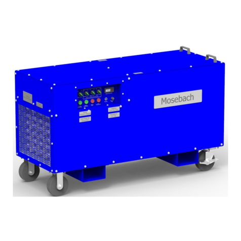
Mosebach HX60-W User manual

HX60-W
HX60-B
HX60-G
OPERATOR’S MANUAL
60 kW HEATER

2
Table of Contents
RECEIVING ........................................................................................................................................... 3
INSPECTING ........................................................................................................................................... 3
LIFTING AND MOVING ......................................................................................................................... 3
SAFETY SYMBOLS ................................................................................................................................. 4
SYMBOL MEANING ............................................................................................................................... 4
SAFETY .................................................................................................................................................. 5
DEFINITIONS........................................................................................................................................... 6
OWER AND GROUND CONNECTIONS ............................................................................................. 7
AIR INTAKES AND EXHAUST ORTS ..................................................................................................... 7
INTAKE AND EXHAUST DUCTING ......................................................................................................... 8
EXHAUST TEM ERATURE ........................................................................................................................ 9
CONNECTING AND DISCONNECTING ............................................................................................... 9
S ECIFICATIONS .................................................................................................................................. 9
O ERATION ........................................................................................................................................ 10
RE-STARTU ........................................................................................................................................ 10
STARTU AND O ERATION ................................................................................................................. 10
REMOTE O ERATION........................................................................................................................... 11
SHUTDOWN .......................................................................................................................................... 12
TROUBLESHOOTING ........................................................................................................................... 12
RE LACING FUSES .............................................................................................................................. 13
RE LACING RESISTORS ...................................................................................................................... 14
REVENTATIVE MAINTENANCE OF HEATER ...................................................................................... 14
O TIONAL EQUI MENT ...................................................................................................................... 15
SERVICE ARTS ................................................................................................................................... 16
A ENDIX A – ELECTRICAL SCHEMATICS ............................................ Error! Book ark not defined.

3
READ ALL INSTUCTIONS!
WARNING: This unit operates with high voltage and has the ability to produce extre e
te peratures. Failure to follow all instructions shown in this anual ay result
in serious injury or death.
RECEIVING
INSPECTING
1. Check the exterior of the shipping container or packaging aterial for obvious
da age.
2. Docu ent and report any exterior da age to the carrier i ediately.
3. Check if casters turn freely and that locks work.
LIFTING AND MOVING
CAUTION: Use proper lifting devices or ethods. Inadequate lifting devices or ethods
can da age the heater. Only units shipped with eyebolts can be safely lifted
fro above. Only units provided with lifting channels ay be safely lifted
using fork lift or lift truck.
Fork Tubes
1A
45°
1
B

4
SAFETY SYMBOLS
The purpose of safety sy bols is to attract your attention to possible dangers. The safety
sy bols and the explanations with the deserve your careful attention and understanding.
The sy bol warnings do not, by the selves, eli inate any danger. The instructions and
warnings they give are no substitutes for proper accident prevention easures.
WARNING: Be sure to read and understand all safety instructions in the Operator’s
Manual, including all safety alert sy bols such as “DANGER,” “WARNING”,
and “CAUTION” before using this unit.
SYMBOL MEANING
DANGER
Indicates a hazardous situation that, if not avoided,
will result in death or serious injury. This sy bol is
li ited to the ost extre e situations.
WARNING
Indicates a hazardous situation that, if not avoided,
could result in death or serious injury.
CAUTION
Indicates a hazardous situation that, if not avoided,
could result in inor or oderate injury.
NOTICE Indicates a situation that, if not avoided, could
result in isuse of or da age to the load bank.
NOTICE - Wear
Eye rotection
Always wear safety goggles or safety glasses when
operating this unit.
NOTICE - Read
Operator’s
Manual
To reduce risk of injury, read and understand entire
operator’s anual before operating unit.
NOTICE - Let
Fans Run
Let fans run for at least 3 inutes after turning off
test power before turning fans off.
NOTICE - Do
Not Block
Airflow
Unit ay overheat without proper airflow

5
CAUTION –
Blown Debris
To reduce risk of injury to persons or da age to the
unit, re ove objects that can be oved by the
cooling fans of the unit.
WARNING –
Electrical
Shock
This unit can potentially operate at high voltage
and current. I proper use can lead to
electrocution, causing serious injury or death.
CAUTION –
Burn and fire
hazard
Exhaust air and surfaces ay be hot
CAUTION –
Moving arts
Moving parts can cut or crush. Keep hands clear.
Do not operate with guards re oved.
SAFETY
WARNING: This heater is designed to handle only one specified voltage. Work on heater
internal syste s should only be atte pted by highly-trained technicians and
only when power has been disconnected and cannot be reconnected to the
unit.
CAUTION: Heaters ust be installed and used in accordance with local codes. Cables
ust be able to safely handle the voltages and current expected. Size cables
for a voltage drop of 2% or less. Insulation on the cabling ust be suitable for
the conditions that the cables will be subjected to.
NOTICE: IMPORTANT INSTRUCTIONS
When using electrical appliances, basic precautions should always be followed to reduce
the risk of fire, electrical shock, and injury to persons, including the following:
1. Read all instructions before using this heater.
2. This heater is hot when in use. To avoid burns, do not let bare skin touch hot
surfaces. Use handles when oving this load bank. Keep co bustible aterials,
such as furniture, pillows, bedding, papers, clothes, and curtains at least 20 feet
fro all sides of the heater

6
3. Extre e caution is necessary when any heater is used by or near children or
invalids and whenever the heater is left operating and unattended.
4. Always unplug heater when not in use.
5. Do not operate any heater with a da aged cord or plug or after the heater
alfunctions or has been dropped or da aged in any anner. Discard heater
or return to authorized service facility for exa ination and/or repair.
6. Do not run cord under carpeting. Do not cover cord with throw rugs, runners, or
si ilar coverings. Do not route cord under furniture or appliances. Arrange cord
away fro traffic areas and where it will not be tripped over.
7. Connect to properly grounded outlets only.
8. Do not insert or allow foreign objects to enter any ventilation or exhaust opening
as this ay cause an electric shock or fire, or da age the heater.
9. To prevent a possible fire, do not block air intakes or exhaust in any anner. Do
not use on soft surfaces, like a bed, where openings ay beco e blocked.
10. The heater has hot parts inside. Do not use it in areas where gasoline, paint, or
fla able liquids are used or stored.
11. Use this heater only as described in this anual. Any other use not
reco ended by the anufacturer ay cause fire, electric shock, or injury to
persons.
12. Always plug heaters directly into a wall outlet/receptacle. Never use with a re-
locatable power tap (outlet/power strip).
13. “SAVE THESE INSTRUCTIONS”
DEFINITIONS
VAC Volt Alternating Current Voltage
A
Amperes Current
kW Kilowatt Power
Min Minutes Ti e
Sec Seconds Ti e
CFM Cubic Feet per
Minute Volu etric Air Flow
F M Feet per
Minute Air Speed

7
OWER AND GROUND CONNECTIONS
WARNING: ELECTRIC SHOCK HAZARD. All power connections ust be connected or
covered. Failure to do so will expose operators to possible shock and the
possibility of grounding-out or shorting-out of the test power source.
All power connections ust be covered or connected. Failure to do so will allow applied
voltages to be present on exposed etal parts of the connectors. Operators could receive
an electrical shock if they co e in contact with these exposed conductors. If a loose
conductor contacts an exposed etal part of a “hot” receptacle, it could lead to
grounding-out or shorting-out of the source generator.
WARNING: ELECTRIC SHOCK HAZARD. The grounding lug ust be connected to earth
ground. Operating without a grounding connection could lead to injury or
death.
When the Heater is in operation the grounding ca ust be fir ly and electrically
connected to earth ground. Failure to do so could allow deadly voltage to be present on
the surface of the enclosure. The grounding connection provides a low resistance path to
ground. This grounding protects the operator fro the possibility of electrical shock.
AIR INTAKES AND EXHAUST ORTS
CAUTION: All air intakes and exhaust ports ust be clear and fully open. Each Heater
has one or ore air intakes designed for proper air flow. Reducing or blocking
air flow will lead to overheating and Heater failure.
Custo er Ca -Lock
Connections
Ground
Ca
2

8
High volu es of cooling air are needed to prevent load ele ents fro overheating. By their
very nature, resistors under load change electrical energy to heat. This heat ust be
re oved fro the unit. The fans, intake, and exhaust ports are sized to provide the proper
a ount of cooling air. Preventing or li iting air flow will allow the Heater to overheat.
Keep intake at least four feet away fro walls and obstructions.
NOTICE: To increase the life of the load ele ents, allow the fans to run at least 3 inutes
after the load is re oved or until exhaust air is cool.
CAUTION: Good air flow keeps the Heater cool but can very easily ove light debris
such as paper, cardboard, and dust with great velocity. Loose aterials
around the Heater, especially near the intake and exhaust, ust be secured
to prevent ove ent. Material on the exhaust side ay be blown into and
injure a bystander. Material near the intake ay be taken into the Heater
da aging internal co ponents.
INTAKE AND EXHAUST DUCTING
NOTICE: Ducting will cause so e air flow reduction. Incorrect ducting can severely reduce
air flow to the heating ele ents. Severe reduction in air flow will lead to heater
failure.
So e i portant considerations when installing ducting with your heater:
Only use ducting that can connect to the intake or exhaust adapters designed by
Mosebach Manufacturing. Other adapter designs ay allow you to connect
incorrectly sized ducting which ay result in heater failure.
Use ducting with a 14” or 20” dia eter that can be attached to the adapters supplied
by Mosebach Manufacturing.
Keep the ducting as straight as possible. If bends are required, ensure the bend radius
is larger than 40”.
NOTICE: All ducting should be secured. Unsecured ducting on the intake end ay
collapse, reduce air flow and cause the heater to fail. Unsecured ducting on
the exhaust ay ove to an undesired location and cause da age.
Use no ore than 50’ of ducting.

9
EXHAUST TEM ERATURE
WARNING: FIRE AND BURN HAZARD. Keep fla able aterial at least 40 feet away fro
the Heater. A great deal of heat is expelled fro the Heater. Te peratures
inside the Heater are sufficient to ignite fla able fu es or aterials. Failure
to aintain proper housekeeping and properly securing fla able aterial
could lead to fire, burns, and/or injury.
Even with sufficient air flow, internal co ponent te perature will exceed 400 degrees F. Air
and aterial several feet fro the Heater can be heated to te peratures in excess of 150
degrees F. Fla able aterials ust not be kept around the Heater. Heat fro the Heater
could ignite this aterial.
Fla able fu es or aterial such as paper could be drawn into the Heater, ignited, and
expelled fro the exhaust port. Operators standing on the exhaust side of the Heater ay
be exposed to high te peratures or possibly burning aterials. Unless proper housekeeping
is practiced in the vicinity of the Heater while it is in operation, fire could result.
CONNECTING AND DISCONNECTING
WARNING: BURN HAZARD. Atte pting to connect or disconnect leads while Heater is in
operation can lead to injury or death. Connecting or disconnecting plugs and
receptacles while current is flowing or voltage is present ay cause and
electrical arc.
Before aking or breaking any connections to the heater, it should be confir ed that the
source is de-energized and no voltage or current is present.
S ECIFICATIONS
Cooling Fan 480VAC, 3 phase, 60Hz, 0.5 HP, 1641 CFM
Control Power 1 0VAC, 1 phase, 60 Hz from step down transformer
Rating Continuous duty
Power Factor 1.0
Load Elements The current at each step is subject to a manufacturing tolerance of ±5%.
Enclosure
Light-weight metal enclosure with casters and lifting eyes for easy maneuvering.
Electro-statically painted powder coat, Blue: PPG PCTZ50108
Touch up paint is Pantone 80-c color. Plastikote custom color universal blend.
Air inlet and outlet are covered by metal screens.
Heat is discharged horizontally.

10
Optional
Equipment
14” or 0” flexible duct.
Exhaust duct transition for 14” or 0” flexible duct.
Wired remote temperature control with thermocouple ports.
Unit Weight 180 lbs.
Outer-Most
Dimensions
30 5/16” x 18 13/16” x 34.36” without fork channels or duct transition.
O ERATION
RE-STARTU
1. Check housekeeping in the operational area and correct all unsafe conditions.
Failure to do this ay result in debris being blown around and ay cause a fire
hazard.
2. Connect the Heater’s grounding ca to a known earth ground at the job site.
Failure to do this ay result in a fatal electrical shock.
3. Check the control panel and ove all switches to the OFF position.
NOTICE: All air intakes and exhaust ports ust be clear and fully open.
Reducing or blocking air flow will lead to overheating and Heater
failure.
4. Position Heater so that air will flow freely into the intakes and out of the exhaust
ports. Ensure that there are no fla able aterials close to the exhaust.
5. Make power connections via ca -locks. The unit will only operate at
480VAC±5%.
STARTU AND O ERATION
1. Energize upstrea source of power.
2. Press the Main Power button.
The blower will start and the green air flow light will co e on.
NOTICE: Failure to have proper air flow will cause unit to overheat and fail.
Operating the heater with a flickering green la p will lead to
da age.
3. Check your fans for air flow.

11
Air should be co ing fro the exhaust port and the green air flow light should
co e on.
4. Check to see that only green la ps are lit. Operating heater with flickering green
la p will lead to da age.
NOTICE: If you apply a voltage that is higher than the Heater is designed to
handle, it will fail. If you have an incorrect voltage or phase
configuration connected, your heater ay fail.
5. Set the Ther ostat to the desired te perature.
6. Turn Heating Power ca switch to desired position (20kW, 40kW, or 60kW). Hot air
should be co ing fro exhaust grill.
CAUTION: Exhaust grill will rise to a te perature high enough to cause burns.
Fla able aterial in the path of the exhaust air can reach a
te perature where the aterials will co bust.
NOTICE: Panel Ther ostat will not control the te perature of the enclosure
being heated unless the heater in co pletely within the enclosed area.
If you wish to keep the heater outside of the enclosure either another
eans of onitoring and controlling te perature ust be used or you
ust use a re ote ther ostat.
REMOTE O ERATION
An option available for the HX60 is a re ote ther ostat. Ensure that when a re ote
ther ostat is used that the ther ostat is co pletely within the enclosure that is to be
heated. If the re ote ther ostat is not within the enclosure to be heated, then another
eans of onitoring and controlling te perature ust be used.
1. Connect re ote ther ostat to the heater provided. Ensure that the twist lock is
fully engaged.
2. Place the re ote ther ostat in the enclosure to be heated.
3. Ther ostat installed on the heater will not function when the re ote ther ostat is
connected.
4. Connect and place ther ocouple(s).
• One or two ther ocouples ay be used.

12
• Using one ther ocouple will control heater based on the local te perature of
that ther ocouple.
• Using two ther ocouples will control heater based on the average of the two
local te peratures of ther ocouples.
• When placing ther ocouple(s), keep ten feet fro the unit and not in direct
exhaust.
• When using two ther ocouples, for opti al results do not place close to one
another.
SHUTDOWN
1. Place the Heating Power switch in the OFF position.
2. Allow fans to operate at least 3 inutes or until exhaust air is cool before shutting
the off.
NOTICE: This cooling period will extend the life of your Heater.
3. Press the Main Power button.
5. Disconnect upstrea power source.
6. Disconnect A, B, and C ca -locks.
7. Disconnect ground ca -lock
8. Move unit to storage.
TROUBLESHOOTING
Thermostat/Bug Killer
Will Not Turn On
Make sure the correct 1 0v receptacle is powered.
Ensure POWER button is ON
Ensure thermocouples are connected.
Blower Will Not Turn
On
Check for debris preventing fan from turning.
Check control fuse (FC). See Figure 5.
Load Steps Will Not
Turn On
Check if OVER TEMPERATURE red light is on.
Check if TIP FAULT red light is on.
Check control fuse. See Figure 5.
Check resistor continuity. See schematic.
Check resistor step fuses. See figure 5

13
Over Temperature
Light
This is an indication that the internal cabinet temperature has exceeded 150°F.
Make sure the cabinet is ventilated.
Check over temperature sensors (OTS) see figure 4.
Tip Fault Light This indicates the unit is not level.
Do not try to operate unit while tipped or tilted more than 15° from horizontal.
Voltage Acceptable
Light Will Not Turn On
The heater has a built in voltage sensing system to protect itself. If the voltage is not
within ±5% of 480VAC it will not operate. The voltage sensing system also protects the
unit from a phase loss or phase imbalance of ±10%.
Airflow Light Stays Red
Check to see if blower is on.
Check air path for obstruction that may prevent proper air flow.
Ensure that the blower is turning in the proper direction
Green Air Flow Light
Flickers
Air flow is very low and intermittently falls below the acceptable level. Continuing to
operate the heater with a flickering green lamp will lead to damage.
Check without ductwork on. Then ensure duct is clear.
RE LACING FUSES
1. Use a #3 Phillips head screwdriver to loosen the 12 pan head screws that secure the lid
of the load bank. Re ove all 12 screws.
2. Re ove the lid, as shown in Figure 3A.
3. Locate the defective fuse. All five internal fuses are located in the area called out in
figure 3B. Re ove the fuse and replace it with an identical fuse (MMC Part #EC-9500-
0247)
¼”-20 Pan
Head Screw
FV and FT Fuses
3A
3
B

14
To replace fuse FS1, locate the fuse holder cap on the far right of the switch panel. Turn the
fuse holder cap counter-clockwise and pull the cap with the fuse attach out of the panel.
Replace the fuse with an identical 10A fuse (MMC Part #EC-9500-1577). After the fuse has
been replaced, insert the fuse cap into the appropriate hole and twist clockwise to lock in
place.
RE LACING RESISTORS
Contact Mosebach Manufacturing Co.
REVENTATIVE MAINTENANCE OF HEATER
NOTICE: Do not use a power washer to clean off the exterior of the unit. It is high voltage
electrical equip ent.
Component Action Frequency
Entire Unit Walk around the load bank and
inspect for :
a) Obvious amage
b) Loose hardware
Check every use
All exterior bolts that hold the
sheet metal.
Tighten the ¼-20 hardware to 5
ft.-lbs.
Check monthly.
Resistance readings Using an ohm meter, check each
step for the correct resistance.
The reactors should have
continuity between input and
output. These values are part of
Appendix B wiring schematic.
Check every 6 months
Electrical Components/ Wiring Check throughout the unit for
loose wires, or electrical
components that are no longer
Check every 6 months
4

15
secure to their mounting plate.
Fan Check the fan for damage that
could cause the airflow to change
such as damaged or missing
bearing, or damaged blades.
Check Annually
Contactors Ensure contacts are opening and
closing
Check Annually
O TIONAL EQUI MENT
Description Part Number
14” Ø Exhaust Transition FR-0400-036
25’ Long 14” Ø Exhaust Duct HW-9000-0789
20” Ø Exhaust Transition FR-0400-0375
25’ Long 20” Ø Exhaust Duct HW-9000-0730
emote Control Kit RC-HX60
Fork Channels FR-0400-0374-B, -G, or -W
6B
6
A
5

16
SERVICE ARTS
2
1
0 Initial Release BSB 11/6/15
Rev.
escription Rev. By ate
Copyright © 2015 Mosebach Manufacturing Co pany
MOSEBACH MANUFACTURING COMPANY
1417 McLaughlin Run Road • Pittsburgh, PA 15241-3103 USA
T: 412.220.0237 Custo er Care
F: 412-220-0236
www. osebachresistors.co
OM-HX60.docx Nove ber 6
th
, 2015
“SAVE THESE INSTRUCTIONS”
Part Number
Fan BLWR-0400-00 3
esistor
Elements
RA-0055-0 8-01
RA-0055-0 8-0
RA-0055-0 8-03
RA-0055-0 8-04
RA-0055-0 8-05
RA-0055-0 8-06
Fuses 1A = EC-9500-0 47
10A = EC-9500-1577
Breakers EC-9500-16
Temperature
Controller EC-9500-1391
Thermocouples Remote = EC-9500-139
Internal = EC-9500-1619
emote
Thermostat Cord WA-0055-0044
Contactors EC-9500-1367
Casters Fixed = HW-9000-0603
Swivel = HW-0900-0609
This manual suits for next models
2
Table of contents
Other Mosebach Heater manuals
Popular Heater manuals by other brands

Pinnacle Climate Technologies
Pinnacle Climate Technologies REMINGTON REM-16-TTC-B User's manual & operating instructions

Dimplex
Dimplex FW 550S Installation and operating instructions

GVA
GVA GRH12K15 instruction manual

Tutco-Farnam
Tutco-Farnam Heat Torch 150 quick guide

Ideal Heating
Ideal Heating Halo user guide

Euromate
Euromate 482181 Original instructions