X100L Load Bank
2
Read all instructions before using the load bank
Contents
1.
Components .............................................................................................................................. 3
Total Assembl ................................................................................................................................. 3
2) Specifications ............................................................................................................................... 4
a)
X100L Load Bank ............................................................................................................ 4
3) Receiving ...................................................................................................................................... 5
4) Safet ........................................................................................................................................... 5
a)
Grounding ............................................................................................................................. 6
b)
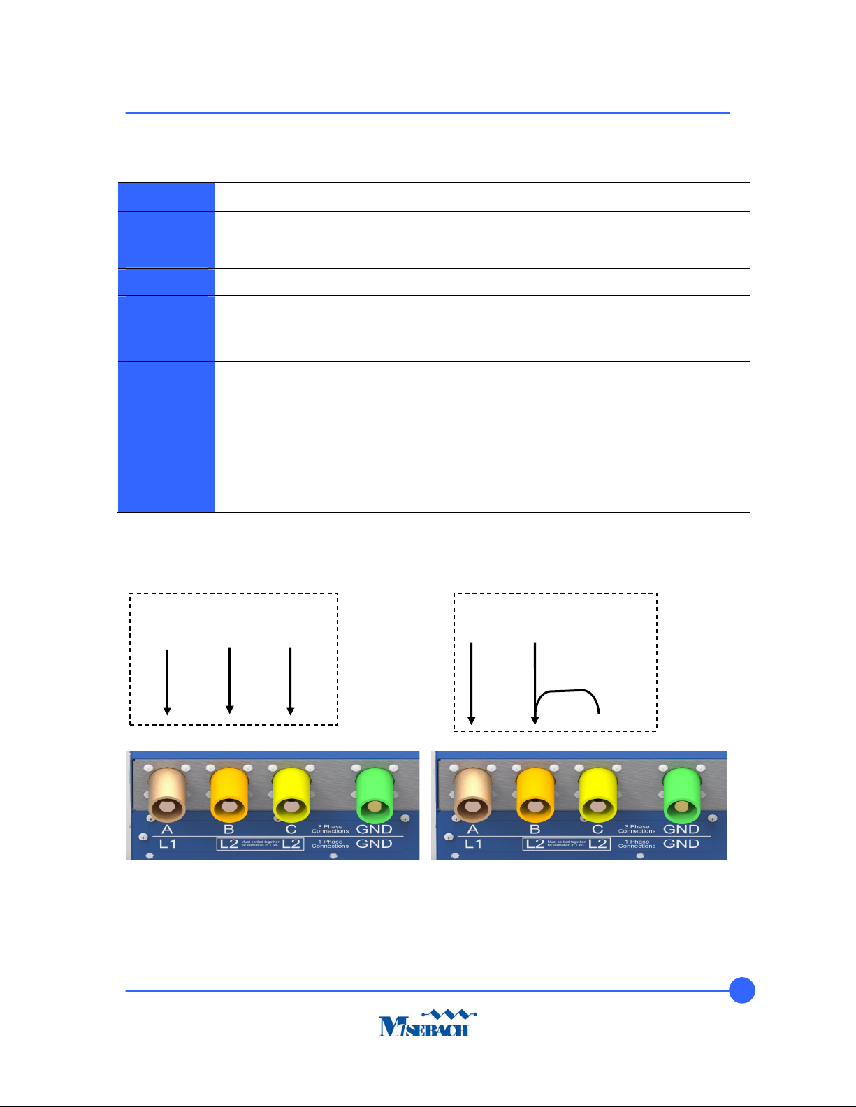
Power connections ............................................................................................................... 7
d)
Air intakes and exhaust ports ............................................................................................... 7
e)
Exhaust temperature ............................................................................................................ 7
f)
Connecting and disconnecting ............................................................................................. 8
5)
Operation ................................................................................................................................... 8
a)
Pre-startup ............................................................................................................................ 8
b)
Startup .................................................................................................................................. 9
c)
Testing .................................................................................................................................. 9
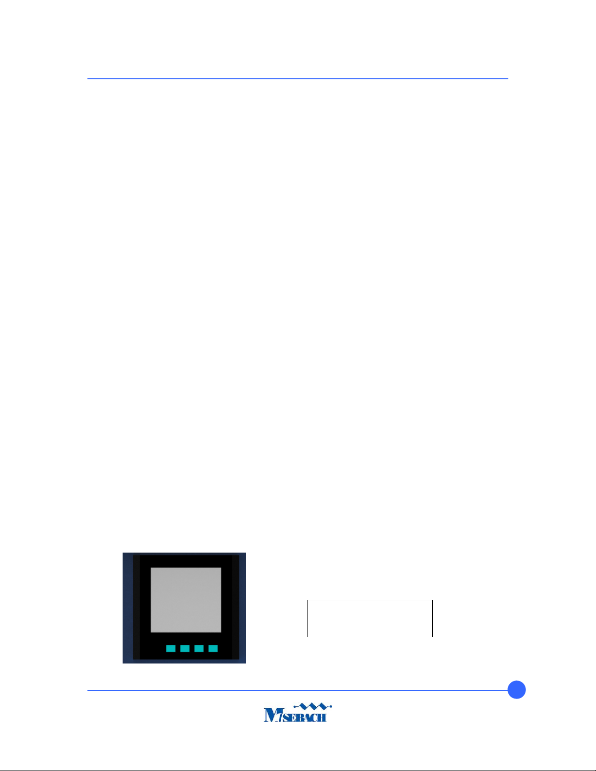
d)
Acuvim II Power Meter.......................................................................................................... 9
e)
Shutdown ............................................................................................................................ 10
6)
USB Communication Port ....................................................................................................... 10
7)
Troubleshooting ....................................................................................................................... 11
8)
Replacing Fuses ...................................................................................................................... 12
9)
Replacing Resistors ................................................................................................................ 13
10)
Preventative Maintenance of the Load Bank ...................................................................... 15
11)
Service Parts ...................................................................................................................... 16
Figure list:
1) Total Assembl of X100L Load Bank
2) Grounding Cam
3) Switch Panel
4) Acuvim II Power Meter
5) T pical USB A to USB B male
6) Blower/Control/Main Fuses
7) Thermal Switch
8) Replacing Fuses
9) Switch Panel Support Bolts
10) Replacing Resistors
11) Resistor/Contactor Connections