Mosebach X250S Operation manual

X250S
Load Bank

X250S Load Bank
2
Read all instructions before using the load bank
Contents
Contents ........................................................................................................................................... 2
1)
Receiving ...................................................................................................................................
a.
Load Bank .............................................................................................................................
b.
Manual ..................................................................................................................................
2)
Specifications ............................................................................................................................ 4
a.
Mechanical ............................................................................................................................ 4
i.
Lifting ............................................................................................................................... 4
ii.
Enclosure ......................................................................................................................... 4
iii.
Cooling ............................................................................................................................. 4
b.
Electrical ............................................................................................................................... 5
i.
Control power .................................................................................................................. 5
ii.
Load power ...................................................................................................................... 5
iii.
Cooling ............................................................................................................................. 5
)
Safety ........................................................................................................................................ 6
a.
Grounding ............................................................................................................................. 6
b.
Power Connection ................................................................................................................ 6
c.
Intake and Exhaust Ports ..................................................................................................... 6
d.
Misuse of Product ................................................................................................................. 6
e.
Common Best Practices ....................................................................................................... 7
4)
Operation ................................................................................................................................... 8
a.
Pre-Start Up .......................................................................................................................... 8
b.
Start Up ................................................................................................................................. 8
c.
Applying and Disconnecting Load ........................................................................................ 8
d.
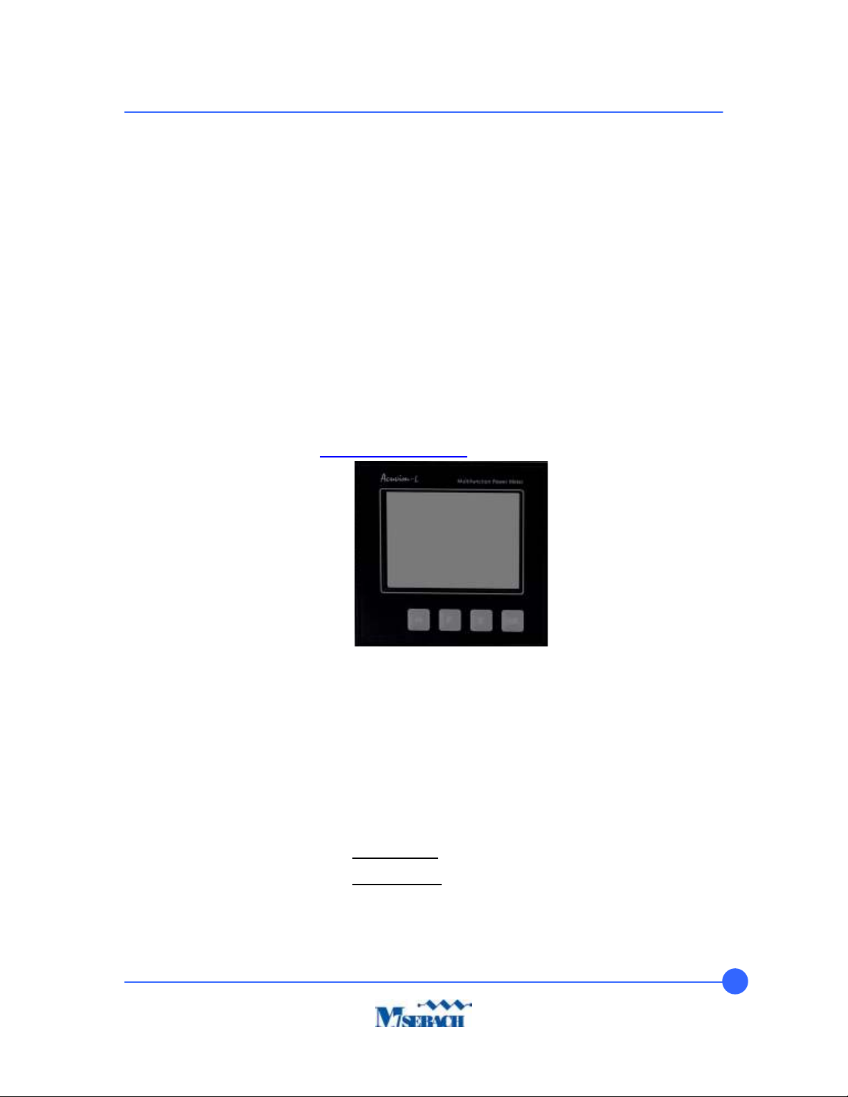
Acuvim II Power Quality Meter ............................................................................................. 9
e.
Shut Down ............................................................................................................................ 9
5)
Troubleshooting ....................................................................................................................... 10
a.
Load bank will not turn on ................................................................................................... 10
b.
Blower will not turn on......................................................................................................... 10
c.
Load steps will not turn on .................................................................................................. 10
d.
Over temperature fault ........................................................................................................ 10
6)
Maintenance ............................................................................................................................ 11
a.
Replacing a fuse ................................................................................................................. 11
i.
Main Control (FC) Fuse ................................................................................................. 11
ii.
Meter (FMA, FMB, FMC) Fuses .................................................................................... 11
iii.
Load Power (FLA1, FLA2, FLB1, FLB2, FLC1, FLC2) Fuses ....................................... 12
b.
Replacing Contactors ......................................................................................................... 12
c.
Replacing Resistors ............................................................................................................ 12
d.
Preventative Maintenance .................................................................................................. 1
7)
Service Parts ........................................................................................................................... 14
8)
Copyright ................................................................................................................................. 15

X250S Load Bank
3
1) Receiving
Check the unit for obvious damage and report any exterior damage to the carrier
immediately.
a. Load Bank
1x X250S Load Bank
Casters and Lifting Bar are Optional
b. Manual
1x X250S Owner’s Manual

X250S Load Bank
4
2) Specification
a. Mechanical
i. Lifting
The X250S load bank is equipped with fork tube for lifting or may be
equipped with an optional lifting bar. DO NOT lift the unit by any other
means; this could cause severe damage.
ii. Enclosure
1. Electro-statically applied powder coat, Blue: PPG PCUP7010 .
2. Air inlet and exhaust are covered by metal screens.
. Heat is discharged horizontality.
iii. Cooling
The X250S load bank is equipped with ten 7 inch panel fan .
Fork
Channels
Optional
Lifting Bar

X250S Load Bank
5
b. Electrical
i. Control power
The unit is equipped with a 120VAC 10A plug to supply 120VAC 60Hz
external control power.
ii. Load power
1. The unit is designed to operate at 208/240/480VAC 3-Pha e or
120/240VAC 1-Pha e load power. See the tables below for
operating specifications at each voltage.
Phase Operation
1 Phase Operation
2. The kW output at each step is subject to a manufacturing
tolerance of ±5%.
. The unit is designed for continuous duty at 1.0 power factor.
iii. Cooling
1. The blowers in the unit are powered off of the auxiliary 120VAC
10A 60Hz plug. Customer Connections
iv. Connect the ground source to the grounding Cam Lock connector.
v. Connect the de-energized source power cables power Cam Lock
connectors.
Resolution (kW) Capacity (kW) Current at Capacity (Amps)
480VAC 240VAC 208VAC 480VAC 240VAC 208VAC 480VAC 240VAC 208VAC
5 5 3.7 250 250 185 300.70 01.41 514.25
Resolution (kW) Capacity (kW) Current at Capacity (Amps)
240VAC 120VAC 240VAC 120VAC 240VAC 120VAC
2.50 0. 3 125.00 31.25 521.00 2 0.00

X250S Load Bank
6
3) Safety
a. Grounding
The load bank must be firmly and electrically connected to earth ground via the
grounding found on the unit. Failure to do so could allow deadly voltage to be
present on the surface of the enclosure. The grounding connection provides a
low resistance path to ground. This grounding protects the operator from the
possibility of electrical shock.
b. Power Connection
All power connections must be connected or guarded. Failure to do so will
expose the operators to shock, causing severe damage or death. Without
properly guarded connections, the unit is in danger of grounding-out or shorting-
out the test power source.
c. Intake and Exhau t Port
The unit must have free-flowing air through the intake and exhaust ports to
provide adequate cooling to the resistive elements. The resistive elements
convert electrical energy into heat. If the unit does not have a free flowing intake
and exhaust port, the heat will build up inside of the unit and cause mechanical
failure, leading to an electrical short circuit, ultimately damaging the unit and test
power source.
To increase the life of the resistive elements, allow the fans to run at least three
minutes after the load is removed.
No ductwork is permitted on the intake or exhaust of this unit as it will cause
backpressure and limit the cooling of the resistive elements.
Keep intake clear for 6 ft. and exhaust port for 20 ft. to allow full free-flowing.
d. Mi u e of Product
DO NOT exceed the recommended load limit of the test power source equipment
manufacturer. Damage of the test power source equipment will occur if over-
powered.

X250S Load Bank
7
e. Common Be t Practice
i. Read all instructions before using this load bank.
ii. This load bank is hot when in use. To avoid burns, do not let bare skin
touch hot surfaces. Keep combustible materials at least 6 feet (1.8
meters) from the front of the load bank and keep them away from the
sides and rear.
iii. Do not operate any load bank with a damaged cord or plug or after the
load bank malfunctions or has been dropped or damaged in any manner.
Discard load bank or return to authorized service facility for examination
and/or repair.
iv. Always unplug load bank when not in use.
v. Do not run cord under carpeting. Do not cover cord with throw rugs,
runners, or similar coverings.
vi. Arrange cord away from traffic areas and where it will not be tripped
over.
vii. Connect to properly grounded outlets only.
viii. Do not insert or allow foreign objects to enter any ventilation or exhaust
opening as this may cause an electric shock or fire, or damage the
heater/load bank.
ix. To prevent a possible fire, do not block air intakes or exhaust in any
manner.
x. Do not use it in areas where gasoline, paint, or flammable liquids are
used or stored.
xi. Use this load bank only as described in this manual. Any other use not
recommended by the manufacturer may cause fire, electric shock, or
injury to persons.
xii. Always plug load banks directly into a wall outlet/receptacle. Never use
with a re-locatable power tap (outlet/power strip).
xiii. This load bank includes a visual alarm to warn that parts of the load bank
are getting excessively hot. If the alarm light goes on, immediately turn
the load bank off and inspect for any objects on or adjacent to the load
bank that may cause high temperatures. DO NOT OPERATE THE
LOADBANK WITH THE ALARM LIGHT ON.
xiv. SAVE THESE INSTRUCTIONS.

X250S Load Bank
8
4) Operation
Please contact Mosebach Manufacturing if you are planning on operating the load bank
in ambient temperatures above 46 ºC.
Ambient plus heat generated by the resistive elements can cause electrical components
to possibly malfunction.
a. Pre-Start Up
i. Check housekeeping in the operational area and correct all unsafe
conditions.
ii. Failure to do this may result in debris being blown around and may
cause a fire hazard.
iii. Check the switch panel and move all switches to the OFF position.
iv. Position the load bank so that air will flow freely into the intake and out of
the exhaust port.
v. All air intakes and exhaust ports must be clear.
b. Start Up
i. Connect the grounding Cam Lock on the unit directly to a known earth-
ground.
ii. Connect all de-energized load power to Cam Lock connections on the
unit.
iii. Energize the load power source with an acceptable voltage.
iv. Turn the MAIN on/off power switch to the ON position. The unit will only
run if an acceptable voltage is supplied. The meter, green Main Power
switch light, and Voltage Acceptable light will turn on when an acceptable
voltage is supplied.
c. Applying and Di connecting Load
i. Start with the Main Power switch located in the ON position and the
Master Load switch in the OFF position.
ii. Turn the Blower switch to the ON position. Load can only be applied if
the blower is on and the unit is getting adequate airflow.
iii. “Shock” Loading
1. Begin with the Master switch in the OFF position.
2. Place the desired test step switches in the ON position.
. Place the Master switch ON to engage all selected load
simultaneously.
iv. “Step” Loading
1. Begin with the Master switch in the ON position.

X250S Load Bank
9
2. Place desired step switches in the ON position to apply load step
by step.
v. Disconnect individual steps by placing the step switches in the OFF
position and/or disconnect all load simultaneously by placing the Master
switch in the OFF position.
vi. “Step” and “Shock” loading can be used in conjunction with one another
during testing.
vii. Repeat tests as needed.
d. Acuvim II Power Quality Meter
i. Press the “VA” button on the front of the meter to view and cycle through
the line voltage and current options.
ii. Press the “P” button on the front of the meter to view and cycle through
the Power Reading and Power Factor options.
iii. You will find more detailed instructions on the use of your meter by
visiting https://accuenergy.com/ and creating an Accuenergy account.
e. Shut Down
i. Ensure the Master switch and all step switches are in the OFF position.
ii. Allow blower(s) to operate for at least three minutes (or until exhaust air
is cool) before shutting them off.
This cooling period will extend the life of your load bank.
iii. Turn the Main Power Switch to the OFF Position.
iv. De-energize the external power source (if applicable) and the load power
source.
v. Remove the de-energized external power source cable.
vi. Remove the de-energized load power Cam Locks from the unit (if
applicable).
vii. Remove the ground Cam Locks from the unit (if applicable).
viii. Remove Ethernet/Data connections (if applicable).

X250S Load Bank
10
5) Trouble hooting
a. Load bank will not turn on
i. Make sure the Main Power switch is in the ON position.
ii. Check the control fuses.
b. Blower will not turn on
i. Make sure the load bank is turning on.
ii. Check for debris preventing the fan(s) from turning.
iii. Check the blower fuses.
c. Load tep will not turn on
i. Make sure the load bank is turning on.
ii. Make sure the test power source is energized.
iii. Make sure the blower is on.
iv. Make sure the Master switch is in the ON position.
v. Check if the over temperature red light is on.
vi. Check the main power fuses.
vii. Check for resistor continuity.
d. Over temperature fault
i. Turn off the unit and disable the source power immediately.
ii. This is an indication that the internal cabinet temperature has exceeded
150 ºF.
iii. Make sure the cabinet is ventilated.
iv. Make sure the temperature sensor is operating. The temperature sensor
should be normally closed below 150 ºF.

X250S Load Bank
11
6) Maintenance
All maintenance should be conducted on a de-energized unit. Operator is to confirm
prior to performing any maintenance.
a. Replacing a fu e
i. Main Control (FC) Fuse
This fuse is located on the front of the switch panel of the load bank and
may be removed by pushing down and twisting the front of the fuse
cover.
ii. Meter (FMA, FMB, FMC) Fuses
These fuses are located under the lid of the load bank. They may be
accessed by removing the 6 screws on the top of the unit. The fuses can
be found on the din rail located on the panel inside. To remove a fuse
from the holder, pry the fuse out of the spring locked fuse holder.
Control Fuse
Meter Fuses

X250S Load Bank
12
iii. Load Power (FLA1, FLA2, FLB1, FLB2, FLC1, FLC2) Fuses
These fuses are located under the lid of the load bank. They may be
accessed by removing the 6 screws on the top of the unit. The fuses can
be found on the bus bars located on the panel inside. To remove a fuse,
remove the screws attaching is to the bus bar.
b. Replacing Contactor
Contact Mosebach Manufacturing Co. if there is a contactor that needs to be
replaced.
c. Replacing Re i tor
Contact Mosebach Manufacturing Co. if there is a problem with the resistors or if
a resistor needs to be replaced.
Load Power
Fuses

X250S Load Bank
13
d. Preventative Maintenance
Do not use a power washer to clean off the exterior of the unit. It is high voltage
electrical equipment.
Action Frequency
Walk around the unit and inspect for:
a) Obvious damage
b) Loose hardware
Every use
Cold Resistance Check Every 6 months
Air Flow Test Every 6 months
Power Test Every 6 months
Open Control Panel and Inspect for:
a) Loose wire connections
b) Visually damaged components
Every 6 months
Inspect Fans Annually
Inspect Resistors for:
a) Damage to coils
b) Delamination of the mica
Annually
Contactors are opening and closing Annually

X250S Load Bank
14
7) Service Part
Part umber
Blowers EC-9500-1434
Meter EC-9500-217
Green Illuminated Switch EC-9500-190
Red Light EC-9500-1904
OTS Sensor EC-9500-2182
Fuse – 10A Type AGC EC-9500-1577
Fuse – 1A EC-9500-0247
Fuse 450A EC-9500-091
Resistor Elements
RA-0055-0395-1
RA-0055-0395-2
RA-0055-0395-3
RA-0055-0395-4
RA-0055-0395-5
RA-0055-0395-
RA-0055-0395-7
RA-0055-0395-8
RA-0055-0395-9
RA-0055-0395-10
RA-0055-0395-11
RA-0055-0395-13

X250S Load Bank
15
8) Copyright
Copyright © 2018 Mosebach Manufacturing Company
MOSEBACH MANUFACTURING COMPANY
1417 McLaughlin Run Road • Pittsburgh, PA 15241- 10 USA
T: 412.220.02 7 Customer Care
F: 412-220-02 6
www.mosebachresistors.com
OM-X250S.doc January 29, 2018
“SAVE THESE INSTRUCTIONS”
Table of contents
Other Mosebach Test Equipment manuals