3M Dynatel 2273ME Series User manual

3M™Dynatel™
Cable/Pipe/Fault Advanced Locator
2250ME/2273ME Series
(With 3-watt, 5-watt, or 12-watt Transmitter)
Operator’s Manual
2250ME
2250ME-iD
2273ME
2273ME-iD
February 2009
78-8130-6151-8-E 3

2 78-8130-6151-8-E
Contents
Safety Information ................................................................................................ 4
About This Manual ............................................................................................... 4
Quick Start ............................................................................................................ 5
Menu Screens...................................................................................................... 10
Configuring The Receiver ................................................................................... 12
Buried Cables And Pipes .................................................................................... 15
Receiver Modes................................................................................................... 18
Depth and Current Estimate................................................................................ 20
Frequencies ......................................................................................................... 21
Locating in Directional Peak Mode .................................................................... 22
Locating Active Duct Probes (Sondes) ............................................................... 25
Buried Sheath Faults And Earth/Return Faults ................................................... 26
3M™Electronic Markers and 3M™EMS iD Markers......................................... 28
Locating 3M™EMS Markers.............................................................................. 29
Marker Depth Estimate....................................................................................... 31
Creating/Editing Templates for 3M™EMS iD Markers...................................... 33
Writing iD Markers............................................................................................. 36
Modifying Marker Data to be Programmed........................................................ 37
Reading iD Markers............................................................................................ 38
GPS Operation .................................................................................................... 39
Reviewing Marker History.................................................................................. 43
Other Applications .............................................................................................. 44
Cable Identification............................................................................................. 45
Help Mode .......................................................................................................... 46
3M™Dynatel™PC Tool Kit................................................................................. 46
Self Test Of Receiver .......................................................................................... 47
Product Description And Optional Accessories.................................................. 47
Receiver Specifications ....................................................................................... 49

78-8130-6151-8-E 3
Congratulations! You have just purchased one of the finest, most advanced locating
devices available today!
The 3M™Dynatel™Cable/Pipe/Fault Locators 2250ME-iD/2273ME-iD are designed
with all of the functionality of previous Dynatel models, and iD versions have the
enhanced capability to read and write user information into the 3M EMS iD markers.
Information such as a pre-programmed identification number, facility data, application
type, placement date and other details can all be read, stored and downloaded to your
PC for enhanced resource management with this revolutionary equipment. The Dynatel
Cable/Pipe/Fault Locators 2250ME-iD/2273ME-iD will also search for two different
types of utility markers simultaneously. When used in conjunction with a hand-held
GPS the ability to transmit path and marker coordinates multiplies the potential to
the mapping industry. This equipment provides a simple system for mapping utility
information directly into CAD and GIS systems.
3M is dedicated to bringing you premium equipment with outstanding reliability, backed
by one of the best warranties in the business and outstanding service.
Visit our website at http://www.3M.com/dynatel for more application notes.

4 78-8130-6151-8-E
Safety Information
Please read, understand and follow all safety information contained in these instructions
prior to the use of the 3M Cable/Pipe/Fault Advanced ME-Series Locator. Retain these
instructions for future reference.
Intended Use
The 3M Cable/Pipe/Fault Advanced ME-Series Locator is used to identify the placement
of underground utility lines. The system must be installed as specified in the 3M Cable/
Pipe/Fault Advanced Locator 2250ME/2273ME Series Operator Manual. It has not been
evaluated for other uses or locations. If this equipment is used in a manner not specified
by 3M, the protections provided by the equipment may be impaired.
mWARNING
If this equipment is used in a manner not specified by 3M, the protections provided by the
equipment may be impaired.
Explanation of Signal Word Consequences
m Warning: Indicates hazardous situation which if not avoided, could result in
death or serious injury.
m Caution: Indicates hazardous situation which if not avoided, could result in
minor or moderate injury.
Explanation of Product Safety Label Symbols
Do not throw away in normal trash.
cWarning: Risk of electric shock
About This Manual
There are two basic models included in the 3M Dynatel Locator 2200M Series. The
2250ME is designed for cable/pipe locating. The 2273ME is designed for cable/pipe
and fault locating. The iD option (read/write capability to 3MTM EMS iD Markers) is
available for both models. There are three transmitter options: 3 Watt, 5 Watt, or 12 Watt.
This instruction manual will include all features. All instructions are applicable to all
products, unless noted.
In order to demonstrate all available functions, the illustrations depict the 2273ME-iD
receiver unit and the 12-watt transmitter. The 2250ME may vary from the
illustrations shown.

78-8130-6151-8-E 5
Quick Start
Transmitter Battery Installation
Loosen the six screws on the battery compartment cover on the bottom of the transmitter.
Remove the cover.
Install six ‘C’ cell batteries (LR14) into the compartment as indicated by the polarity
symbols (+ and –).
Replace the cover and tighten the screws.
Press and hold OFF [T-1] to manually test the batteries. The display and audio will
indicate one of the following levels: (OK w/solid tone = good; LO w/beeping tone =
low; "--" w/no tone = replace)
mCaution
To reduce the risks associated with fire and explosion:
• Do not short, excessively heat, or dispose of batteries in fire.
• Install batteries with proper polarity.
• Use only Alkaline "C" (LR14) sized batteries.
• Do not charge batteries
• Do not use leaking batteries
To reduce the risks associated with environmental contamination:
• Dispose of batteries and electronic components in accordance with all regulations.
• Ensure batteries are installed with correct polarity.
• Always remove batteries when storing the units for long periods of time.

6 78-8130-6151-8-E
Receiver Battery Installation
Remove cap from receiver handle.
Install eight ‘AA’ cell batteries (LR6) into the battery holder as indicated by the polarity
symbols (+ and –).
Attach battery holder to the PP3 connector in the receiver handle, and slide holder into
the handle. Replace the cap.
8 “AA” Alkaline Batteries
1. Twist cap to open battery
compartment.
2. Slide battery compartment
out of handle.
mCaution
To reduce the risks associated with fire and explosion:
• Do not short, excessively heat, or dispose of batteries in fire.
• Install batteries with proper polarity.
• Use only Alkaline "AA" (LR 6) sized batteries.
• Do not charge batteries
• Do not use leaking batteries
To reduce the risks associated with environmental contamination:
• Dispose of batteries and electronic components in accordance with all regulations.
• Ensure batteries are installed with correct polarity.
• Always remove batteries when storing the units for long periods of time.
The receiver batteries are tested for two seconds every time the unit is turned on.
The bar graph on the screen will fill to the relative battery level.
The Battery Icon [8] on the Locate Screen will continuously indicate the battery level.
Cleaning
To clean the unit, wipe with a damp cloth.

78-8130-6151-8-E 7
Service and Accessories
Information regarding service, accessories, or replacement parts can be obtained by
contacting your local 3M Sales Office or 3M Sales Representative.
This equipment does not require annual calibration or maintenance.
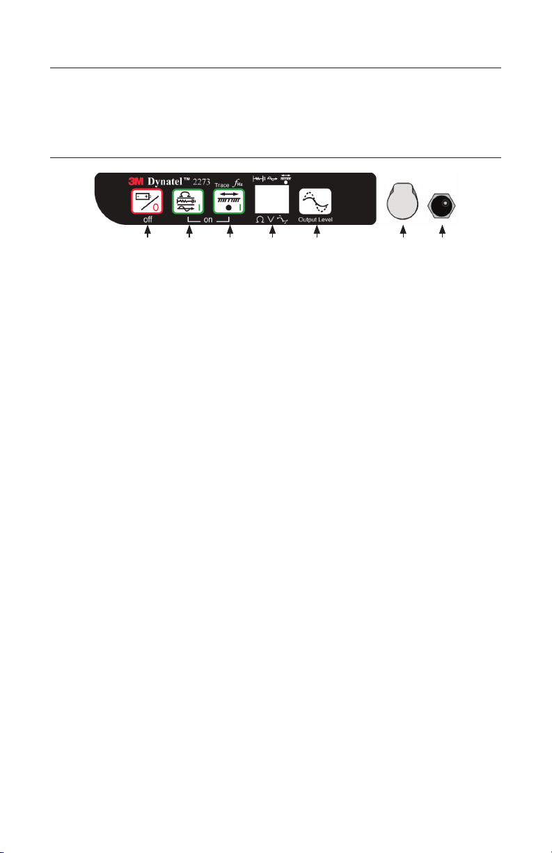
Transmitter Keypad and Connector Definitions
T-1 T-2 T-3 T-4 T-5 T-6 T-7
OFF: [T-1] Turns unit off and performs battery test.
OHM / FAULT / TONE: [T-2] Turns the unit on and cycles through the following
commands when pressed repeatedly.
OHM METER: Measures the continuity of the trace conductor/pipe and its far-end
ground. It is also used to measure the fault resistance to earth.
FAULT LOCATE: (2273ME units only) In this mode, the transmitter sends two
alternating frequencies (577 Hz and 33 KHz) as well as fault signals 10 and 20 Hz.
TONE: In the tone mode, the transmitter generates 577 Hz and 133 KHz signals.
TRACE: [T-3] Turns the unit on and places the unit in Trace mode.
SELECT FREQUENCY: Press TRACE [T-3] repeatedly to cycle the frequency
of the transmitter (577 Hz, 8 KHz, 33 KHz, and 133 KHz). The selected frequency
will be displayed [T-4]. ‘ALL' indicates that multiple frequencies are transmitting
simultaneously.
DISPLAY: [T-4]
INDICATOR FLAGS: These flags coincide with the operational mode of the
transmitter. (From top left to bottom right) Fault mode [T-2] (2273ME units only),
Tone [T-2], Trace mode [T-3], Ohm meter [T-2], Voltage (at start up the transmitter
checks for foreign voltage), and the Output Flag (no flag = low output; flag = high
output; flashing flag = maximum output).
DIGITAL DISPLAY: Indicates frequency, relative current, resistance, battery level
and voltage.
OUTPUT: [T-5] Cycles output level; normal, high and maximum.
Normal=No Flag; High=Flag; Maximum=Flashing Flag
OUTPUT JACK: [T-6] Port for direct connect cables or Dyna-coupler.
EXTERNAL JACK: [T-7] Port to connect cigarette lighter adapter cable, or
rechargeable battery (2200RB). Input voltage level: 9-18 VDC.

8 78-8130-6151-8-E
Maximum Transmitter Output
An external 12V DC source is required for 12-Watt Output. Connecting the rechargeable
battery (2200RB) to the external jack [T-7] will provide this external source, or the
cigarette lighter adapter cable (included with high powered units) can be used to connect
the DC power from a vehicle’s battery source to the transmitter’s external jack {T-7}.
Press Output [T-5] twice for maximum output mode.
The indicator flag will flash when the transmitter is in max output mode.
Note: The external DC source does not charge the internal batteries.
mWARNING
To reduce the risk associated with hazardous voltage:
• Potential for electric shock exists when handling connection cables while the transmitter is
ON. Make all connections prior to powering on the unit. Turn transmitter OFF before handling
connection cables.
• Voltage greater than 240 volts will damage equipment and could cause personal injury or
death. Make all connections before turning on the transmitter. Follow standard procedures
for reducing the voltage.
• Do not change or modify this product in any way.
Rechargeable Battery
The 3M Dynatel Sealed Gel-Cell Battery 2200RB can be used as an auxiliary battery
in 3M™Dynatel™2200 Series Transmitters. It plugs into the external jack [T-7] and
provides power for the transmitter. When the rechargeable battery is plugged in, normal
output, high output, and maximum output is available. When the rechargeable battery is
connected to the transmitter, the alkaline batteries are bypassed. The rechargeable battery
is a lead acid battery rated at 5.4 amp-hours and is equipped with a user replaceable fuse
(5A/32V).
Note: The internal batteries must be at least 5.4 volts. Do not remove the alkaline
batteries from the transmitter when using the rechargeable battery.

78-8130-6151-8-E 9
Receiver Key Pad Definitions
POWER: [1] Turns unit off and on.
SPEAKER: [2] Adjusts the volume of the receiver (off, low, med, high, and Xpand).
SPEAKER ICON [2A]: Indicates the relative volume level of the receiver. When
the third ring is dotted and ‘xpnd' appears below the speaker icon, the receiver is in
“Expander” mode. This mode is used to pinpoint the target cable or pipe.
CONTRAST: [3] The arrows located above and below the contrast icon will adjust the
contrast of the screen.
GAIN: [4] Adjusts the sensitivity of the receiver either up or down to maintain a
satisfactory signal level.
LOCATE/OK: [5] Sets the receiver to trace mode for locating cable or pipe.
Acknowledges setup entries (OK).
MENU: [6] Displays setup screen for configuration of the unit, i.e.: clock, language,
depth units, marker data and frequencies.
BACKLIGHT: [7] Toggles the backlight low, high, and off.
BATTERY ICON: [8] Indicates battery level.
SOFT KEY: [SK] There are four soft keys on the receiver. The function of each key
is shown above the key on the display screen. The functions will change, depending on
the operation mode of the receiver. For instruction purposes, the display command is
followed by [SK] to identify it as a soft key.
SOFT KEY COMMAND: [9] Definitions for each of the four soft key functions.
SIGNAL STRENGTH: [10] Digital reading of the signal the receiver is detecting.
BAR GRAPH: [11] Graphical representation of the received signal.
GAIN LEVEL: [12] Displays relative gain level.
EXTERNAL JACK: [l3] Port to connect cables from external devices such as the earth
frame, a second Dyna-Coupler, or toning coil.
SERIAL PORT: [14] RS232 port to connect the receiver to a PC via straight serial
cable (not included).
EARPHONE JACK: [15] Will fit standard 1/8 inch mini-jack mono earphone plug
(not included).

10 78-8130-6151-8-E
Menu Screens
Main Menu
When the Menu [6] button is pressed, the Main Menu screen appears.
The function appears on the screen above each soft key.
1. Write Mode: System used to write information to RFiD Markers
2. Data/Template: Displays marker history and
template creation/selection screens:
a. Read History – 100 memory locations for
Read RFiD Markers
b. Write History – 100 memory locations for
Programmed RFiD Markers
c. User Templates – Create and edit RFiD
templates for RFiD Markers (max =32)
d. Trace Templates – Create and edit
templates used to identify path (max = 5)
3. COM Setup: Displays second level COM
Port setting screen to configure RS232 port
communication with different devices –
a. PC – Receiver will communicate to a
computer
b. NMEA – Port is configured to accept
coordinates from GPS
c. GIS – Port is configured to send RFiD
information or path information to GPS
device and receive coordinates from GPS.
d. PDA – receiver will send RFiD and path
information in ASCII string.
4. More>>: Advances to next menu screen

78-8130-6151-8-E 11
5. Back<<: Returns to previous screen
6. Setup: Displays second and third level screens
for receiver configuration
a. Depth Units – Choose unit of measure; in,
ft-in, or cm
b. Clock – Date and time stamped on marker
information and depth readings.
c. Language – Toggles between English and
alternate language
d. More>> - Advances to next menu screen
e. Back<< - Returns to previous screen
f. Marker Type – enable and disable marker
utility types
g. Locate Frequencies – enable and disable
receiver frequencies in locate mode
h. Tone/Freq - External Port or Tone
Frequencies – enable and disable frequencies
that are detectable through the external port
of the receiver
i. Power Filter Frequency – Select the power
frequency of the region to aid in 50/60 Hz
interference rejection
j. Audio Configuration – Select audio
response of unit in Directional Peak mode

12 78-8130-6151-8-E
7. Self Test: Displays information about unit and
performs a self check test
8. Help: Offers the user on-screen instructions
Configuring The Receiver
In the setup mode, the units of depth measurement, time, date, and date format can be
set. The receiver can be configured to detect only certain frequencies and/or specific
utility markers. User defined frequencies can be programmed, language of the receiver
can be selected, and tone frequencies set.
Select Depth Units
MENU [6] + More>>[SK] + Setup [SK] + Units [SKToggle]
• Press Units [SK toggle].
• The soft key command
will toggle between inches
(in), centimeters (cm), and
feet/inches (ft-in).
Setting the Receiver Clock
Set the time, date, and date format of the receiver. Depth and Current measurements are
time and date stamped, as well as read write marker information (iD units only).
MENU [6] + More>>[SK] + Setup [SK] +Clock [SK]
• Press the left/right arrow [SK] to highlight the digit
of the date or time to change.
• Press the + or - [SK] to increment or decrement.
• When the date format is highlighted, the format
will toggle between mm/dd/yy and dd/mm/yy.
• Press OK [SK] to save, or Menu [6] to cancel.
Selecting a Language
MENU [6] + More>>[SK] + Setup [SK] + Lang [SKToggle]
The soft key command will cycle through available languages. Alternate languages
can be uploaded to the receiver using the Dynatel™PCTools software. (Available for
download at www.3M.com/dynatel.)

78-8130-6151-8-E 13
Enabling/Disabling Frequencies
MENU [6] + More>>[SK] + Setup [SK] + + More» [SK] + Locate Freq [SK]
The user can select the frequencies that the receiver will detect. All the available
frequencies are listed in four groups (Left to Right: Active, Power, Passive, and
Auxiliary). The Auxiliary group also contains the User Defined Frequencies. (See
Creating User Defined Frequencies.)
1. Press the right arrow [SK] to move the highlight
bar to the section of frequencies to enable, or
disable.
2. Press the up/down arrows [SK] to highlight the
specific frequency.
3. Press Enabl/Disabl [SK]. (Enable denoted by 3)
4. Repeat steps 2 & 3 to enable/disable other
frequencies.
5. Press OK [5] to save.
Selecting External Jack Frequencies (Tone Frequencies)
MENU [6] + More>>[SK] + Setup [SK] + + More» [SK] + Tone Freq [SK]
A coupler can be plugged into the external jack
of the receiver and used to identify cables. (See
Other Applications: Cable Identification.) The
same procedure as above is followed for selecting
frequencies that can be detected by the external jack
found on the bottom of the receiver.
Creating User Defined Frequencies
MENU [6] + More>>[SK] + Setup [SK] + + More» [SK] + Locate Freq [SK]
There are four user defined frequencies available on the receiver. (These frequencies
must be between 50 Hz and 999 Hz.) These frequencies are found in the column on
the far right of the Locate Freq screen (Auxiliary frequencies). These frequencies, once
programmed, will appear in the Locate mode under the Aux [SK] frequency list.
To program the user defined frequencies press the
right arrow [SK] to highlight the Auxiliary group
of frequencies. Press the up/down arrows [SK]
to highlight the user frequency to program. Press
Enabl/Disabl [SK].

14 78-8130-6151-8-E
Press the left/right arrows [SK] to move the square
cursor to a digit. Press Select [SK] to enter the
number in the frequency field.
Press OK [5] to save the programmed frequency, or
press Exit [SK] to cancel. The frequency will appear
in the locate frequency screen as U ###.
Note: To redefine a previously programmed user
frequency, highlight the frequency, press enabl/
disabl, select the back arrow with the cursor, and
press select to delete the previous entry.
Filtering Power Frequency Interference
MENU [6] + More>>[SK] + Setup [SK] + + More» [SK] + More>>[SK] + Filter [SK]
In order to filter out unwanted power influences
while locating with user-defined frequencies, verify
the correct frequency is selected for your location
(default 50 Hz).
Selecting Locating Audio
MENU [6] + More>>[SK] + Setup [SK] + + More» [SK] + More>>{SK} + Audio Config [SK]
The user can choose the audio response of the
receiver when using the Directional Peak mode for
path locating. Highlight the audio selection and press
OK to save.

78-8130-6151-8-E 15
Buried Cables And Pipes
Transmitter Connections
Perform a battery test. Use one of the following three methods to produce a trace signal
on the target pipe or cable.
Direct Connect Method
Plug the direct connect cable into the output jack [T-6] of the transmitter. Connect the
black clip to the ground rod. Place the ground rod in the earth perpendicular to the
suspected cable/pipe path. If necessary, extend the black lead with the Ground Extension
Cable (#9043 available separately).
1. Remove the ground bonding and attach the red clip to the shield of the cable, pipe,
or target conductor. (If locating power cables, the red clip can be attached to the
transformer cabinet, or the meter box).
2. Turn the transmitter on by pressing Ohms [T-2]. The continuity of the circuit will be
measured. The results are displayed [T-4] in ohms and as a tone.
− If the continuity of the circuit is very good (the reading on the display is less
than 3K Ω. and a solid tone from the transmitter is heard) all frequencies can be
used to locate. Always use the lowest frequency available. Lower frequencies are
less likely to ‘bleed over’ to other cables in the same area, and are very good for
tracing over long distances.
− If the circuit reads more than 3K Ω., but less than lOK Ω(indicated by a beeping
tone from the transmitter) it will be necessary to use a higher frequency than 512
Hz or 577 Hz in order to locate the cable/pipe.
− If the circuit reads more than lOK Ω., it will be necessary to use an RF signal
such as 33 KHz or 133 KHz.
− If there is no tone and the transmitter indicates that there is an open circuit (OL
in the display) this could be an indication of a poor ground, or an open-ended
cable or pipe. Use one of the higher frequencies available, at high level. If it is
an open-ended cable or pipe, the receiver's response will decrease suddenly at
the site of the clear or severed end.

16 78-8130-6151-8-E
Note: In the ohms mode, the transmitter can detect voltage as well as ohms. If a low
voltage is detected, the display will alternate between displaying ohms and volts. When
displaying ohms, the flag over the Ωsymbol will be visible. When displaying volts, the
flag over the ‘V' will be visible. When the voltage magnitude is sufficient to impair the
accuracy of the ohms measurement, only voltage will be displayed. If the voltage is
AC, a sine wave will be visible on the display [T--4]. If a high AC voltage is detected, a
rapid beeping tone will be heard.
3. Press the Trace [T-3] repeatedly until the desired frequency appears on the display.
4. Press Output [T-5] to select high output level for longer tracing distances or deep
pipe/cable.
Dyna-Coupler Method
1. Connect the Dyna-Coupler to the transmitter output jack [T-6] using the coupler
cable (9011).
2. Clamp the Dyna-Coupler around the cable or pipe, below any bonds, just before it
enters the earth. The jaws of the coupler must fully close.
3. Press Trace [T-3] to turn on the transmitter. Press again to select 8 KHz, 33 KHz or
133 KHz.
Note: When using a Dyna-Coupler, always select high output level by pressing the
output key [T-5] on the transmitter.

78-8130-6151-8-E 17
Induction Method
If you cannot make a direct connection, or use the 3M™
Dynatel™
Dyna-Coupler clamp
to apply a locating signal on the target, use the induction method. This method uses the
internal coil of the transmitter to generate a magnetic field. This is the least preferred
method of applying a signal on a target conductor because it can easily be picked up by
other non-target conductors in the area. However, it is the preferred method of applying
a signal to multiple cables/pipes in the same trench, and for the ‘two-man sweeping’
application.
1. Verify battery level of transmitter and remove any cables from the output jack.
2. Position the transmitter over the target facility with the hinge of the transmitter over
and in line with the cable/pipe path.
3. Align the Induction Direction arrows on the transmitter with the target conductor.
4. Turn on the transmitter by pressing the Trace [T-3] key.
5. Press Trace [T-3] again to select 33 KHz or 133 KHz.
6. Select High Output level for the best signal-to-noise ratio.
7. Trace the signal path with the receiver using the Induction Peak mode.
The induction mode of the receiver is a mode in which the upper antenna of the receiver
is tuned to minimize distortion from the magnetic field of the transmitter.
Note: The receiver must be at least 25 feet away from the transmitter to begin tracing
the target path.

18 78-8130-6151-8-E
Receiver Modes
Directional Peak
MODE + Directional Peak (DirPk) [SK Toggle]
In DirPk mode, four peak antennas are used to analyze the magnetic field pattern. The
bar graph indicates signal strength and the directional arrows sense the edges of the
magnetic field. The left/right arrows will indicate the direction to the nearest cable that is
in-line with the receiver handle.
As the antenna crosses the cable or pipe, the receiver speaker volume increases to a
maximum, the bar graph [1l] fills from both sides toward the middle, and the numeric
signal strength [10] increases. As the antenna moves off the target path, the speaker
volume decreases and the bar graph opens. Use the bar graph and the numeric signal
indicator to locate the exact target path.
Left of Target Path Directly Over Target Path Right of Target Path
Once the target path has been located, the arrows at the top of the screen will indicate
the location of the target path in relationship to the receiver.
Note: When field distortion (due to congestion) is affecting the receiver the left/right
arrows may not coincide with the bar graph. Use the maximum numerical signal
strength to target the cable or pipe.
Directional Null
MODE + (DirNull) [SK Toggle]
In DirNull mode, as the operator approaches the cable or pipe, the numerical signal will
increase then fall sharply as the receiver crosses the target cable or pipe. The bar graph
fills from both sides toward the middle and the receiver speaker volume decreases. As
the antenna moves off the target path, the bar graph opens, the signal strength increases,
and the speaker volume increases. Gain adjust is automatic in DirNull mode.
The center of the DirNull screen provides a ‘compass view' of the target path. An arrow
will point toward the location of the cable/pipe in 45-degree steps. A solid line will
appear over the cable/pipe, indicating its orientation to the receiver handle.

78-8130-6151-8-E 19
For example:
Figure 1: If the target path is to the right of the
receiver, and running parallel to the operator, the
right arrow will display.
Figure 2: If the target path is to the left and in front
of the operator (not running parallel to the receiver)
the arrow will point toward the top left side of
the screen.
Figure 3: When the receiver crosses the target path,
a solid line will appear, instead of arrows, indicating
the target path and its orientation to the receiver.
Before marking target path, always use directional peak or special peak mode to verify
location.
Special Peak
MODE + (Spl Pk) [SK Toggle]
Special Peak Mode turns on only the peak antenna closest to the ground. Special Peak
Mode is used in applications such as very deep cable, or when the signal is too weak for
normal or directional peak tracing.
Inductive Peak (IndPk)
MODE + IndPk [SK Toggle]
If you cannot make a direct connection, or use the 3M™
Dynatel™
Dyna-Coupler clamp
to apply a locating signal on the target, use the induction method. This method uses the
internal coil of the transmitter to generate a magnetic field.
The induction mode of the receiver is a mode in which the upper antenna of the receiver
is tuned to minimize distortion from the magnetic field of the transmitter.

20 78-8130-6151-8-E
Expanded Mode
When the third ring of the speaker icon is dotted or broken and ‘xpnd’ appears below the
speaker icon, the receiver is in “Expanded” mode. This mode is used for pinpointing a
target cable or pipe. The area of response of the receiver narrows, allowing the locator to
detect very small signal changes.
Depth and Current Estimate
Verifying the target path, depth and current can be helpful tools.
1. Pinpoint the cable or pipe being located.
2. Lower the tip of the receiver to the ground and
press Depth [SK].
− The depth to the target cable or pipe is
displayed in the units specified in the
receiver set up menu. The bold current
reading is a relative current measurement.
This reading can be compared to the current
reading that alternately flashes with the
frequency on the transmitter. The milliamp
reading is an actual current measurement.
− There are two options for measuring depth.
Live depth is a continuous measurement.
1-Shot Depth is an averaging of the depth
reading. When in 1-Shot mode, the unit will
average the depth reading for three seconds,
and then display the result on the screen.
Press Depth [SK] to alternate between the
two modes.
− Five depth readings can be saved with the
time, date and relative current measurements.
3. Pressing Save [SK] will place each entry in sequential order in memory (M1 - M5)
until five readings have been stored. The unit will overwrite saved entries in excess
of five, beginning with M1.
This manual suits for next models
3
Table of contents
Other 3M Test Equipment manuals
Popular Test Equipment manuals by other brands

G.R.A.S.
G.R.A.S. 45CC instruction manual

Sartorius Stedim Biotech
Sartorius Stedim Biotech 16756 operating instructions

BAQ
BAQ alphaDUR mini manual

KYORITSU
KYORITSU KEW FORK 2300 R instruction manual

Desco Europe
Desco Europe Charleswater 99037 Installation, operation and maintenance

Madsen
Madsen zodiac user guide