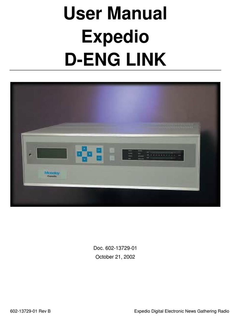
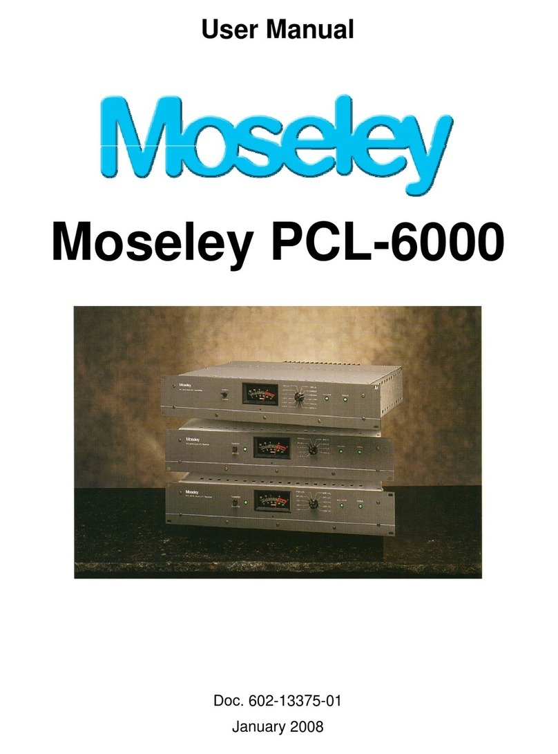
Moseley Starlink SL9003Q User manual

Moseley SL9003Q 602-12016-01 Revision J
User Manual
Starlink SL9003Q
Digital Studio Transmitter Link
Doc. 602-12016-01
Revision J
Released December, 2010

ii
Moseley SL9003Q 602-12016-01 Revision J
WARRANTY
All equipment designed and manufactured by Moseley Associates, Inc., is warranted
against defects in workmanship and material that develop under normal use within a period
of (2) years from the date of original shipment, and is also warranted to meet any
specifications represented in writing by Moseley Associates, Inc., so long as the purchaser is
not in default under his contract of purchase and subject to the following additional
conditions and limitations:
1. The sole responsibility of Moseley Associates, Inc., for any equipment not conforming to
this Warranty shall be, at its option:
A. to repair or replace such equipment or otherwise cause it to meet the represented
specifications either at the purchaser's installation or upon the return thereof f.o.b.
Santa Barbara, California, as directed by Moseley Associates, Inc.; or
B. to accept the return thereof f.o.b. Santa Barbara, California, credit the purchaser's
account for the unpaid portion, if any, of the purchase price, and refund to the
purchaser, without interest, any portion of the purchase price theretofore paid; or
C. to demonstrate that the equipment has no defect in workmanship or material and
that it meets the represented specification, in which event all expenses reasonably
incurred by Moseley Associates, Inc., in so demonstrating, including but not limited to
costs of travel to and from the purchaser's installation, and subsistence, shall be paid by
purchaser to Moseley Associates, Inc.
2. In case of any equipment thought to be defective, the purchaser shall promptly notify
Moseley Associates, Inc., in writing, giving full particulars as to the defects. Upon receipt of
such notice, Moseley Associates, Inc. will give instructions respecting the shipment of the
equipment or such other manner as it elects to service this Warranty as above provided.
3. This Warranty extends only to the original purchaser and is not assignable or
transferable, does not extend to any shipment which has been subjected to abuse, misuse,
physical damage, alteration, operation under improper conditions or improper installation,
use or maintenance, and does not extend to equipment or parts not manufactured by
Moseley Associates, Inc., and such equipment and parts are subject to only adjustments as
are available from the manufacturer thereof.
4. NO OTHER WARRANTIES, EXPRESS OR IMPLIED, SHALL BE APPLICABLE TO ANY
EQUIPMENT SOLD BY MOSELEY ASSOCIATES, INC., AND NO REPRESENTATIVE OR OTHER
PERSON IS AUTHORIZED BY MOSELEY ASSOCIATES, INC., TO ASSUME FOR IT ANY
LIABILITY OR OBLIGATION WITH RESPECT TO THE CONDITION OR PERFORMANCE OF ANY
EQUIPMENT SOLD BY IT, EXCEPT AS PROVIDED IN THIS WARRANTY. THIS WARRANTY
PROVIDES FOR THE SOLE RIGHT AND REMEDY OF THE PURCHASER AND MOSELEY
ASSOCIATES, INC. SHALL IN NO EVENT HAVE ANY LIABILITY FOR CONSEQUENTIAL
DAMAGES OR FOR LOSS, DAMAGE OR EXPENSE DIRECTLY OR INDIRECTLY ARISING FROM
THE USE OF EQUIPMENT PURCHASED FROM MOSELEY ASSOCIATES, INC.

iii
Moseley SL9003Q 602-12016-01 Revision J
SL9003Q Manual Dwg # 602-12016-01 Revision Levels:
SECTION DWG REV ECO REVISED/
RELEASED
Table of Contents 602-12016-TC1 D DCO1065 October 2003
1 602-12016-11 D DCO1065 October 2003
2 602-12016-21 D DCO1065 October 2003
3 602-12016-31 D DCO1065 October 2003
4 602-12016-41 D DCO1065 October 2003
5 602-12016-51 D DCO1065 October 2003
6 602-12016-61 D DCO1065 October 2003
7 602-12016-71 D DCO1065 October 2003
Appendix 602-12016-A1 D DCO1065 October 2003
Figure 5.7 D July 2004
2, 4 & 5 602-12016-01 E May 2005
3.2.1 602-12016-01 F November 2005
4.4.1 602-12016-01 F November 2005
5.2 602-12016-01 F November 2005
G February 2006
Removed Composite and 4-Port MUX 602-12016-01 H October 2007
6.3 602-12016-01 I February 2008
1.3 reference 5W TX option
Appendix F add TP128
602-12016-01 J December 2010

iv
Moseley SL9003Q 602-12016-01 Revision J
Using This Manual - Overview
Section 1: System Features and Specifications
A short discussion of the SL9003Q features and specifications.
Section 2: Quick Start
For the experienced user who wants to get the system up and running as soon as possible,
this section contains typical audio settings, RF parameters, and performance checks.
Section 3: Installation
Detailed system installation information covering:
•Primary power requirements (AC/DC)
•Bench test details (for initial pretest)
•Site installation details (environmental, rack mount and link alignment)
Section 4: Operation
Reference section for front panel controls, LED indicators, LCD screen displays and software
functions:
•Front panel controls & indicators
•Screen Menu Structure – menu tree & navigation techniques
•Screen Summary Tables – parameters & detailed functions.
Section 5: Module Configuration
Listings of jumpers, settings and options useful for diagnosis and custom systems:
•Module configuration
•Troubleshooting guide
Section 6: Customer Service
Information to obtain customer assistance from the factory.
Section 7: System Information
System theory discussion for a better understanding of the SL9003Q:
•System Block Diagrams
•Module Details and Block Diagrams
Appendices
Additional material for reference and design. These include:
•Path Evaluation Information
•Audio Considerations
•Glossary of Terms
•Conversion Chart (microvolts to dBm)
•Spectral Emission Masks
•Redundant Configurations
•Use in Hostile Environments
•FCC Applications Information

v
Moseley SL9003Q 602-12016-01 Revision J
TABLE OF CONTENTS
1. System Features & Specifications .............................................................. 1-1
1.1 System Introduction.................................................................................. 1-1
1.2 System Features....................................................................................... 1-1
1.3 Specifications ........................................................................................... 1-2
1.3.1 System Specifications – Discrete ........................................................... 1-2
1.3.2 Bit Rate, Threshold and Bandwidth for SL9003Q Equipment Variations........ 1-3
1.3.3 Transmitter Specifications .................................................................... 1-3
1.3.4 Receiver Specifications ........................................................................ 1-4
1.3.5 Audio Encoder Specifications ................................................................ 1-4
1.3.6 Audio Decoder Specifications ................................................................ 1-4
1.3.7 Intelligent Multiplexer Specifications ...................................................... 1-5
1.4 Regulatory Notices .................................................................................... 1-6
2. Quick Start ................................................................................................. 2-1
2.1 Unpacking................................................................................................ 2-1
2.2 Notices.................................................................................................... 2-1
2.3 Rack Mount.............................................................................................. 2-2
2.4 Typical System Configurations .................................................................... 2-3
2.5 Transmitter Power-Up Setting..................................................................... 2-5
2.6 Default Settings and Parameters ................................................................. 2-7
2.6.1 Audio ................................................................................................ 2-7
2.6.2 Identifying Audio Connections (4-Channel Discrete) ................................. 2-7
2.6.3 Data Channels on the 6-Port Mux Module ............................................... 2-7
2.6.4 RF Module Parameters ......................................................................... 2-7
2.6.5 QAM Modulator and Demodulator .......................................................... 2-8
2.7 Performance............................................................................................. 2-8
2.7.1 Transmitter Performance Check ............................................................ 2-8
2.7.2 Receiver Performance Check............................................................... 2-10
2.8 For More Detailed Information... ............................................................... 2-10
3. Installation ................................................................................................ 3-1
3.1 Rear Panel Connections ............................................................................. 3-1
3.1.1 Power Supply Slot ............................................................................... 3-1
3.1.2 AC Power Supply ................................................................................ 3-1
3.1.3 DC Input Option ................................................................................. 3-2
3.1.4 Fusing ............................................................................................... 3-3
3.2 Preliminary Bench Tests............................................................................. 3-3
3.2.1 RF Bench Test .................................................................................... 3-4
3.2.2 Discrete Audio and Data Channel Bench Test .......................................... 3-7
3.3 Site Installation ........................................................................................ 3-8
3.3.1 Facility Requirements ........................................................................ 3-11
3.3.2 Power Requirements.......................................................................... 3-11
3.3.3 Rack Mount Installation ..................................................................... 3-11
3.4 Antenna/Feed System ............................................................................. 3-11
3.4.1 Antenna Mounting............................................................................. 3-11
3.4.2 Transmission Line ............................................................................. 3-12
3.4.3 Environmental Seals.......................................................................... 3-12
3.5 Transmitter Antenna Testing .................................................................... 3-13
3.6 Link Alignment ....................................................................................... 3-14

vi
Moseley SL9003Q 602-12016-01 Revision J
4. Operation ................................................................................................... 4-1
4.1 Introduction ............................................................................................. 4-1
4.2 Front Panel Operation................................................................................ 4-1
4.2.1 LCD Display ....................................................................................... 4-1
4.2.2 Cursor and Screen Control Buttons ........................................................ 4-1
4.2.3 LED Status Indicators .......................................................................... 4-2
4.3 Screen Menu Navigation and Structure......................................................... 4-4
4.3.1 Screen Menu Navigation ...................................................................... 4-4
4.3.2 Saving Settings (system-wide) ............................................................. 4-5
4.3.3 Screen Menu Structure ........................................................................ 4-5
4.4 Screen Menu Summaries............................................................................ 4-6
4.4.1 Meter ................................................................................................ 4-6
4.4.2 System: Card View ............................................................................. 4-7
4.4.3 System: Power Supply......................................................................... 4-7
4.4.4 System: Info...................................................................................... 4-7
4.4.5 System: Basic Card Setup .................................................................... 4-8
4.4.6 Factory Calibration .............................................................................. 4-8
4.4.7 SYSTEM: UNIT-WIDE PARAMS ............................................................ 4-11
4.4.8 System: Date/Time ........................................................................... 4-12
4.4.9 System: Transfer .............................................................................. 4-13
4.4.10 System: External I/O (NMS) ............................................................... 4-13
4.4.11 Alarms/Faults ................................................................................... 4-14
4.4.12 Radio: Modem Status (QAM) .............................................................. 4-15
4.4.13 Radio TX Status ................................................................................ 4-19
4.4.14 Radio RX Status................................................................................ 4-21
4.4.15 Radio TX Control............................................................................... 4-21
4.4.16 Radio RX Control............................................................................... 4-22
4.4.17 Radio Modem (QAM) Configure ........................................................... 4-22
4.4.18 Radio TX Configure ........................................................................... 4-23
4.4.19 Radio RX Configure ........................................................................... 4-24
4.4.20 Radio Modem/TX/RX Copy Function ..................................................... 4-24
4.5 Intelligent Multiplexer PC Interface Software............................................... 4-24
4.6 NMS/CPU PC Interface Software................................................................ 4-24
5. Module Configuration ................................................................................. 5-1
5.1 Introduction ............................................................................................. 5-1
5.2 Audio Encoder/Decoder.............................................................................. 5-1
5.2.1 Encoder: AUDIO IN CARD JUMPERS....................................................... 5-3
5.2.2 Encoder: MPEG - ENCODER A SWITCHES ............................................... 5-3
5.2.3 Encoder: MPEG - ENCODER C SWITCHES ............................................... 5-4
5.2.4 Encoder: MPEG - ENCODER M SWITCHES............................................... 5-4
5.2.5 Encoder: S21 - DATA CHANNEL ............................................................ 5-4
5.2.6 Encoder: S22 - BOARD ID .................................................................... 5-5
5.2.7 Encoder: S23 - SYSTEM CONFIG ........................................................... 5-5
5.2.8 Encoder: S31 - SYSTEM CONFIG ........................................................... 5-6
5.2.9 Encoder: S81 - AES/EBU...................................................................... 5-6
5.2.10 Decoder: AUDIO OUT CARD JUMPERS.................................................... 5-7
5.2.11 Decoder: ISO/MPEG RATE .................................................................... 5-7
5.2.12 Decoder: S21 - DATA CHANNEL ............................................................ 5-8
5.2.13 Decoder: S22 - BOARD ID.................................................................... 5-8
5.2.14 Decoder: S23 - SYSTEM CONFIG........................................................... 5-9
5.2.15 Decoder: S32 SYSTEM CONFIG ............................................................. 5-9

vii
Moseley SL9003Q 602-12016-01 Revision J
5.2.16 Decoder: S52 - SYSTEM CLOCK .......................................................... 5-10
5.2.17 Decoder: S81 - AES/EBU ................................................................... 5-10
5.2.18 AES/EBU and SPDIF .......................................................................... 5-10
5.2.19 Analog Audio Gain and Input Impedance .............................................. 5-11
5.2.20 Data Channel Rate ............................................................................ 5-11
5.2.21 Board ID.......................................................................................... 5-11
5.2.22 System Configuration ........................................................................ 5-11
5.3 QAM Modulator/Demodulator.................................................................... 5-12
5.4 IF Card Upconverter/Downconverter .......................................................... 5-12
5.5 Transmit/Receiver Module (RF Up/Downconverter) ...................................... 5-13
5.5.1 Changing Frequency — TX.................................................................. 5-13
5.5.2 Changing Frequency — RX ................................................................. 5-14
5.5.3 Measuring Carrier Frequency — TX ...................................................... 5-15
5.6 Power Amplifier ...................................................................................... 5-16
5.7 MUX Module ........................................................................................... 5-16
5.8 NMS/CPU Module .................................................................................... 5-16
5.8.1 External I/O ..................................................................................... 5-16
5.8.2 Relay Electrical Interface.................................................................... 5-17
5.8.3 Relay Mapping Configuration .............................................................. 5-18
5.8.4 NMS External Output Characteristic ..................................................... 5-21
6. Customer Service ....................................................................................... 6-1
6.1 Introduction ............................................................................................. 6-1
6.2 Technical Consultation ............................................................................... 6-1
6.3 Factory Service......................................................................................... 6-1
6.4 Field Repair.............................................................................................. 6-2
7. System Description .................................................................................... 7-1
7.1 Introduction ............................................................................................. 7-1
7.2 Transmitter.............................................................................................. 7-1
7.2.1 Audio Encoder .................................................................................... 7-2
7.2.2 Intelligent Multiplexer.......................................................................... 7-3
7.2.3 QAM Modulator/IF Upconverter Daughter Card ........................................ 7-3
7.2.4 Transmit Module (Upconverter)............................................................. 7-4
7.2.5 Power Amplifier .................................................................................. 7-5
7.3 Receiver .................................................................................................. 7-5
7.3.1 Receiver Module ................................................................................. 7-7
7.3.2 QAM Demodulator/IF Downconverter Daughter Card ................................ 7-8
7.3.3 Intelligent Multiplexer.......................................................................... 7-8
7.3.4 Audio Decoder.................................................................................... 7-9
A. Path Evaluation Information ...................................................................... A-1
A.1 Introduction................................................................................................. A-1
A.1.1 Line-of-Sight .......................................................................................... A-1
A.1.2 Refraction .............................................................................................. A-1
A.1.3 Fresnel Zones ......................................................................................... A-1
A.1.4 K Factors ............................................................................................... A-2
A.1.5 Path Profiles ........................................................................................... A-4
A.2 Path Analysis ............................................................................................... A-4
A.2.1 Overview ............................................................................................... A-4
A.2.2 Losses ................................................................................................... A-4
A.2.3 Path Balance Sheet/System Calculations .................................................... A-4
A.2.4 Path Availability & Reliability..................................................................... A-7

viii
Moseley SL9003Q 602-12016-01 Revision J
A.2.5 Methods of Improving Reliability................................................................ A-8
A.2.6 Availability Requirements ......................................................................... A-8
A.2.7 Path Calculation Balance Sheet ................................................................. A-9
B. Audio Considerations ................................................................................. B-1
B.1 Units of Audio Measurement........................................................................... B-1
B.1.1 Why dBm? ............................................................................................. B-1
B.1.2 Audio Meters .......................................................................................... B-1
B.1.3 Voltage-Based Systems............................................................................ B-1
B.1.4 Old Habits Die Hard ................................................................................. B-1
C. Glossary of Terms ...................................................................................... C-1
D. Microvolt – dBm – Watt Conversion (50 ohms) ..........................................D-1
E. Spectral Emission Masks ............................................................................ E-1
E.1 500 kHz Allocation ........................................................................................ E-1
E.2 300 kHz Allocation ........................................................................................ E-2
E.3 250 KHz Allocation ........................................................................................ E-2
F. Redundant Backup with TP128, TP64, or TPT-2 Transfer Panels................ F-1
F.1 TP128/TP64 System Features ......................................................................... F-1
F.2 TP128/TP64 System Specifications .................................................................. F-1
F.3 TP128/TP64 Installation ................................................................................. F-2
F.3.1 TP128/TP64 Rack Installation .................................................................... F-2
F.3.2 TP128 Power Supply ................................................................................ F-2
F.3.3 TP64 Power Supply .................................................................................. F-2
F.4 Equipment Interconnection............................................................................. F-2
F.4.1 Starlink SL9003Q Backup Operation ........................................................... F-2
F.4.2 Digital STL with Analog STL Backup using a TPT-2........................................ F-7
F.4.3 Discrete Starlink with DSP6000 Backup using a TPT-2 .................................. F-9
F.5 Operation ...................................................................................................F-13
F.5.1 Hot/Cold Standby Modes .........................................................................F-13
F.5.2 Panel Controls and Indicators ...................................................................F-13
F.5.3 Master/Slave Operation & LED Status........................................................F-14
F.6 Software Settings ........................................................................................F-15
F.6.1 Starlink Transmitter Settings....................................................................F-15
F.6.2 TP128 Settings.......................................................................................F-15
F.6.2 TP64 Settings ........................................................................................F-15
G. Optimizing Radio Performance For Hostile Environments ..........................G-1
H. FCC APPLICATIONS INFORMATION - FCC Form 601...................................H-1
LIST OF FIGURES
Figure 2-1. SL9003Q Typical Rack Mount Bracket Installation ...................................... 2-2
Figure 2-2. SL9003Q 2 or 4 Channel Digital STL Setup ............................................... 2-4
Figure 2-3. SL9003Q Repeater Setup ....................................................................... 2-5
Figure 2-4. Radio TX Status Performance Check ........................................................ 2-9
Figure 2-5. RX Modem Status Performance Check.................................................... 2-10
Figure 3-1. SL9003Q AC Power Supply..................................................................... 3-1
Figure 3-2. SL9003Q DC Power Supply..................................................................... 3-2

ix
Moseley SL9003Q 602-12016-01 Revision J
Figure 3-3. SL9003Q Discrete Audio Bench Test Setup ............................................... 3-4
Figure 3-4. Receiver Site Installation Details ........................................................... 3-10
Figure 3-5. Rack Ear Bracket Mounting Methods ...................................................... 3-11
Figure 3-6. Transmitter Antenna Testing ................................................................ 3-13
Figure 4-1. SL9003Q Front Panel............................................................................. 4-1
Figure 4-2. Main Menu Screen ................................................................................ 4-4
Figure 4-3. Radio Launch Menu Screen Navigation ..................................................... 4-5
Figure 4-4. Top Level Screen Menu Structure ............................................................ 4-6
Figure 4-5. Factory Calibration-Radio TX Screens....................................................... 4-9
Figure 4-6. Factory Calibration-Radio RX Screens ...................................................... 4-9
Figure 4-7. Factory Calibration-QAM Modem Screens ............................................... 4-10
Figure 4-8. Factory Calibration-System Screens ...................................................... 4-10
Figure 5-1. Audio Encoder Front Panel ..................................................................... 5-1
Figure 5-2. Audio Decoder Front Panel ..................................................................... 5-2
Figure 5-3. Audio Encoder PC Board / Switch & Jumper Settings .................................. 5-3
Figure 5-4. Audio Decoder PC Board / Switch & Jumper Settings.................................. 5-7
Figure 5-5. AES/EBU-XLR Encoder Connection......................................................... 5-10
Figure 5-6. SPDIF-XLR Encoder Connection............................................................. 5-10
Figure 5-7. AES/EBU-XLR Decoder Connection ........................................................ 5-11
Figure 5-8. SPDIF-XLR Decoder Connection ............................................................ 5-11
Figure 5-9. Data Channel Connector- DSUB (9-pin).................................................. 5-11
Figure 5-10. QAM Modem Front Panel .................................................................... 5-12
Figure 5-11. Up/Down Converter Front Panel .......................................................... 5-13
Figure 5-12. SL9003Q NMS Card ........................................................................... 5-16
Figure 5-13. NMS Card External I/O Pinout ............................................................. 5-17
Figure 5-14. Representative Internal Relay Wiring ................................................... 5-18
Figure 5-15. NMS External RSL Voltage Curve (Pin 10) ............................................. 5-21
Figure 7-1. SL9003Q Transmitter System Block Diagram ............................................ 7-1
Figure 7-2. Audio Encoder Block Diagram ................................................................. 7-2
Figure 7-3. IF Upconverter Daughter Card Block Diagram ........................................... 7-3
Figure 7-4. Transmit Module (Upconverter) Block Diagram.......................................... 7-4
Figure 7-5. SL9003Q RF Power Amplifier Block Diagram ............................................. 7-5
Figure 7-6. SL9003Q Receiver System Block Diagram ................................................ 7-6
Figure 7-7. Receiver Module Block Diagram .............................................................. 7-7
Figure 7-8. SL9003Q IF Downconverter Daughter Card Block Diagram.......................... 7-8
Figure 7-9. Audio Decoder Block Diagram................................................................. 7-9
Figure F-1. Starlink SL9003Q Transmitter Main/Standby Configuration ......................... F-4
Figure F-2. Starlink SL9003Q RX Main/Standby Connection (w/OPTIMOD)..................... F-5
Figure F-3. Receiver Audio Output Switching-External Control (Discrete or Digital Audio) F-6
Figure F-4. Starlink TX & RX NMS-Transfer I/O Connection ......................................... F-8
Figure F-5. Starlink QAM TX with DSP/PCL TX Backup and TPT-2 Connection ................F-10
Figure F-6. Starlink QAM RX with DSP/PCL RX Backup and Optimod Connection ............F-11
Figure F-7. Starlink QAM RX with DSP/PCL RX Backup and Router Connection ..............F-12
Figure F-8. TP64 Front Panel..................................................................................F-13
Figure F-9. STARLINK – TP64 Control Cable Adaptor 230-12127-01 ............................F-16
LIST OF TABLES
Table 1-1. Bit Rate, Threshold, & Bandwidth ............................................................. 1-3
Table 2-1. Encoder/Decoder Typical Settings ............................................................ 2-7
Table 4-1. LED Status Indicator Functions (Transmitter) ............................................. 4-2

x
Moseley SL9003Q 602-12016-01 Revision J
Table 4-2. LED Status Indicator Functions (Receiver) ................................................. 4-3
Table 4-3. LED Status Indicator Functions (Repeater/Full Duplex Systems) ................... 4-3
Table 5-1. NMS External I/O Pin Descriptions .......................................................... 5-17
Table A-1. Typical Antenna Gain.............................................................................. A-5
Table A-2. Free Space Loss .................................................................................... A-5
Table A-3. Transmission Line Loss ........................................................................... A-5
Table A-4. Branching Losses ................................................................................... A-6
Table A-5. Typical Received Signal Strength required for BER of 1x10E-4* .................... A-6
Table A-6. Relationship Between System Reliability & Outage Time .............................. A-8
Table A-7. Fade Margins Required for 99.99% Reliability, Terrain Factor of 4.0, and
Climate Factor of 0.5 ....................................................................................... A-8
Table F-1. TP128/TP64 Transmitter Master/Slave Logic .............................................F-14
Table F-2. TP128/TP64 Receiver Master/Slave Logic..................................................F-14
Table G-1. Interleave Setting vs. Delay ....................................................................G-2

Section 1: System Features & Specifications 1-1
Moseley SL9003Q 602-12016-01 Revision J
1. System Features & Specifications
1.1 System Introduction
The Moseley STARLINK 9000 is the first all-digital, open-architecture, modular system for
CD-quality audio transmission. The versatility and power of the STARLINK 9000 comes from
a complete range of plug-and-play personality modules.
The SL9003Q Digital Studio-Transmitter Link (DSTL) provides a transmitter/receiver pair
that conveys high quality digital audio across a microwave radio path. Typically, program
material is transmitted from a studio site to a remote transmitter site, to a repeater site, or
in an intercity relay application.
Utilizing spectrally efficient digital Quadrature Amplitude Modulation (QAM) technology, the
SL9003Q delivers four discrete 16/24-bit linear audio channels with RS-232 data over
standard FCC Part 74 (950 MHz) STL frequency allocations.
As a discrete STL, the AES/EBU digital audio I/O, combined with a built-in variable sample
rate converter, provide seamless connection to the all-digital air chain without compression.
The system has provisions for asynchronous auxiliary data channels (up to 38,400 baud)
that are used for communication in remote control applications. Plug-in MPEG audio
modules and a digital multiplexer support additional program, voice, FSK, async and sync
data channels.
The high spectral efficiency of the SL9003Q is achieved by user-selectable 16, 32, 64 or 128
QAM. Powerful Reed-Solomon error correction with interleaving, coupled with 20-tap
adaptive equalization, provide unsurpassed error-free signal robustness in hostile RF
environments for which there is no comparable benefit in analog transmission.
1.2 System Features
In addition to establishing a new industry standard for studio-transmitter link performance,
the SL9003Q incorporates many new and innovative features:
•Linear 16/24-bit digital audio performance.
•Higher system gain, 26 dB more than analog composite STL.
•Degradation-free multiple hops.
•Configurable for up to 4 linear audio program channels per STL system.
•No crosstalk between channels.
•No background chatter from co-channel or adjacent-channel interference.
•Built-in AES/EBU digital audio interface.
•Operation through fractional T1 networks.
•Built-in data channels alleviate the need for FM subcarrier data channels.
•Extensive LCD screen status monitoring.
•Peak-reading LED bar graph display for all audio channels.
•Adjustable bit error rate threshold indication for monitoring transmission quality.
•Important status functions implemented with bi-color LED indicators.
•Modular construction that provides excellent shielding, high reliability, easy servicing,
and upgrade capability.
•Selectable RF spectral efficiency.
•Sample rate converter (SRC) for digital audio operation from 30 to 50 kHz.

1-2 Section 1: System Features & Specifications
Moseley SL9003Q 602-12016-01 Revision J
1.3 Specifications
Note: Other combinations of frequencies, bandwidths, and output power may be available
but not specifically listed here. Please contact Moseley Sales Department for availability.
Specifications are subject to change without notice.
1.3.1 System Specifications – Discrete
4 linear (32 or 44.1 kHz sample rate) + 2 data channels;
2 linear (44.1 kHz sample rate) + LAN (500 kbps) with 6-port MUX
Audio Capacity
(Typical Configurations)
2 linear (44.1 kHz sample rate) + 1 data channel
Frequency Range(s) 160-240 MHz
330-512 MHz
800-960 MHz
1340-1520 MHz
1650-1700 MHz
(Fully Synthesized, front-panel programmable, no adjustments)
Frequency Step Size 25 kHz
Occupied Bandwidth 200/250/300/500 kHz
Note: Rate & QAM mode dependent, see Table 1-1 for details.
RF Spectral Efficiency See Appendix
Threshold Performance See Table 1-1 below for details.
Audio Frequency Response vs. Sample Rate:
32 kHz: 0.5 Hz-15 kHz; -3 dB bandwidth, +/- 0.2 dB flatness
44.1 kHz: 0.5 Hz-20 kHz; -3 dB bandwidth, +/- 0.2 dB flatness
48 kHz: 0.5 Hz-22.5 kHz; -3 dB bandwidth, +/- 0.2 dB flatness
Audio Distortion <0.01%
<0.01% at 1 kHz (compressed)
Audio Dynamic Range 92 dB Digital (AES/EBU) IN/OUT
83 dB Analog IN/OUT
Audio Crosstalk < -80 dB
Audio Data Coding Method Linear
ISO/MPEG (Layer II)
Audio Sample Rate Selectable 32, 44.1, 48 kHz built-in rate converter
Audio Coding Time Delay Linear: 0 ms
ISO/MPEG: 22 ms
Channel Coding Time Delay
(Add to Audio Coding Delay
above)
Depends on Interleave Factor - QAM Modem Configuration:
1 - 2.6 mS
2 - 3.7 mS
3 - 5.0 mS (typical)
4 - 6.0 mS
6 - 8.0 mS
12 - 14.0 mS
Bit Error Immunity >1X10E-4 for no subjective loss in audio quality
Async Data Channels One for each audio pair
Aggregate Transmission
Rates
Depends on number of audio channels
Diagnostics FWD Power, REV Power, TX Lock, Radiate, RSL, BER, RX Lock

Section 1: System Features & Specifications 1-3
Moseley SL9003Q 602-12016-01 Revision J
Status Indicators Full Duplex: Fault, Alarm, Loopback, TX, TXD, RX, RXD, NMS/CPU.
Transmitter: Fault, Alarm, VSWR, Radiate, Standby, AFC Lock, Modulator
Lock, NMS/CPU.
Receiver: Fault, Alarm, Attenuator, Signal, BER, AFC Lock, Demodulator
Lock, NMS/CPU.
Fault Detection and Logging REV Power, PA Current, LO Level, Exciter Level, RSL, BER, Synth Level,
Modem Level
Alarm Detection and
Logging
FWD Power, AFC Lock , PA Temp, MBAUD, DBAUD, DFEC
Temperature Range Specification Performance: 0 to 50º C
Operational: -20 to 60º C
1.3.2 Bit Rate, Threshold and Bandwidth for SL9003Q Equipment Variations
Table 1-1. Bit Rate, Threshold, & Bandwidth
Bit Rate 10E-4 Threshold
(dBm)
Bandwidth **
(kHz)
Application (kbps) 16
QAM
32
QAM
64
QAM
16
QAM
32
QAM
64
QAM
2-Channel Linear Audio
32 kHz Sample
& 1 data channel
1024 -93 -91 -89 300 250 200
2-Channel Linear
48 kHz Sample
& 1 Data Channel or 44.1 with LAN
1536 -91.5 -89.5 -87.5 450 375 300
4-Channel Linear
32 kHz Sample
& 2 Data Channels
2048 -90 -88 -86 600 500 400
** Measured using FCC 50/80 dB Digital Mask.
1.3.3 Transmitter Specifications
Frequency Range 160-240 MHz
330-512 MHz
800-960 MHz
1340-1520 MHz
1650-1700 MHz
(Fully Synthesized, front-panel programmable, no adjustments)
RF Power Output 1.0 Watt @ 16, 32, 64, 128 QAM, 160-240/330-512/800-960 MHz
0.5 Watt @ 16, 32, 64, 128 QAM, 1340-1520/1650-1700* MHz
*5.0W option is available
RF Output Connector Type N (female), 50 ohms
Frequency Stability 0.00001 % (0.1 PPM), 0 – 50º C
Spurious and Harmonic
Emission
< -60 dBc
Type of Modulation User Selectable: 16, 32, 64, 128 QAM
FCC Emission Type
Designation
200KD7W
250KD7W
300KD7W
500KD7W
FCC Identifier CSU9WKSL9003Q74
Power Source AC: Universal AC, 90-260 VAC, 47-63 Hz
DC: +/- 12 VDC, +/- 24 VDC, +/- 48 VDC, Isolated chassis ground

1-4 Section 1: System Features & Specifications
Moseley SL9003Q 602-12016-01 Revision J
Power Consumption 70 Watts
Dimensions 17” W x 14” D x 5.2” H (3RU) [ 43.2 cm x 35.6 cm x 13.2 cm]
Weight Net weight = 23.6 lbs. (10.7 kg). Shipping weight = 25.6 lbs. (11.6 kg)
1.3.4 Receiver Specifications
Type of Receiver Dual conversion superheterodyne
1st IF = 70 MHz, 2nd IF = 6.4 MHz
Frequency Range 160-240 MHz
330-512 MHz
800-960 MHz
1340-1520 MHz
1650-1700 MHz
(Fully Synthesized, front-panel programmable, no adjustments)
Receiver Dynamic Range –35 dBm to –95 dBm
Adjacent Channel Rejection 10 dB with similar Digital SL9003Q system or with DSP 6000/PCL 6000 link.
Image Rejection 70 dB min
Antenna Connector Type N (female), 50 ohms
Type of Demodulation Coherent 16, 32, 64, 128 QAM
Error Correction Reed-Solomon, t = 8
Equalizer 20 tap adaptive
Frequency Stability 0.00001 % (0.1 PPM), 0 – 50º C
BER Threshold Mute Adjust -95 dBm
Receiver Sensitivity See Table 1-1 above.
Power Source Receiver power consumption: 65 Watts
Dimensions 17” W x 14” D x 5.2” H (3RU) [ 43.2 cm x 35.6 cm x 13.2 cm]
Weight Net weight = 25.5 lbs. (11.6 kg). Shipping weight = 27.5 lbs. (12.5 kg)
1.3.5 Audio Encoder Specifications
Sample Rate 32/44.1/48 kHz selectable, built-in rate converter
Analog Audio Input XLR female, electronically balanced,
600/10k ohm selectable, CMRR > 60 dB
Analog Audio Level -10 dBu to +18 dBu, rear panel accessible
Digital Audio Input AES/EBU: Transformer balanced, 110 ohm input impedance
SPDIF: Unbalanced, 75 ohm input impedance
Data Input 9-pin D male RS-232 levels
Async. 300 to 38400 bps selectable
ISO/MPEG Modes Mono, dual channel, joint stereo, stereo (ISO/IEC 111172-3 Layer II)
Sample Rate: 32/44.1/48 kHz selectable
Output Rate: 32/48/56/64/80/96/112/128/160/192/224/256/320/384 kHz selectable
1.3.6 Audio Decoder Specifications
Sample Rate 32/44.1/48 kHz selectable, built-in rate converter
Analog Audio Output XLR male, electronically balanced, low Z/600 ohm selectable
Analog Audio Level -10 dBu to +18 dBu, rear panel accessible
Digital Audio Output AES/EBU: Transformer balanced, 110 ohm input impedance
SPDIF: Unbalanced, 75 ohm input impedance

Section 1: System Features & Specifications 1-5
Moseley SL9003Q 602-12016-01 Revision J
Data Output 9-pin D male RS-232 levels
Async. 300 to 38400 bps selectable
ISO/MPEG Modes Mono, dual channel, joint stereo, stereo (ISO/IEC 111172-3 Layer II)
Sample Rate: 32/44.1/48 kHz selectable
Input Rate: 32/48/56/64/80/96/112/128/160/192/224/256/320/384 kHz selectable
1.3.7 Intelligent Multiplexer Specifications
Capacity 6 local Ports
Aggregate Rates Up to 2.048 Mbps
Resolution 8000 bps, 768-2048 kbps; 4000 bps, 384-768 kbps; 2000 bps, 192-384 kbps, 1000 bps,
96-192 kbps; 500 bps, 48-96 kbps; 250 bps, 24-48 kbps
Clocks Internal, Derived, External Port
Local Port
Interfaces
Choice of:
UDP Stream/Ethernet
Voice; Low Speed Async Data (RS-232),
High Speed Sync Data (V.35, RS-449)
Data Rates Low Speed 300-38400 bps;
Voice 16, 24, 32, 64 kbps;
High Speed to 2040 kbps
Trunk V.35 or RS-449

1-6 Section 1: System Features & Specifications
Moseley SL9003Q 602-12016-01 Revision J
1.4 Regulatory Notices
FCC Part 15 Notice
Note: This equipment has been tested and found to comply with the
limits for a Class A digital device, pursuant to part 15 of the FCC
Rules. These limits are designed to provide reasonable protection
against harmful interference when the equipment is operated in a
commercial environment. This equipment generates, uses, and can
radiate radio frequency energy and, if not installed and used in
accordance with the instruction manual, may cause harmful
interference to radio communications. Operation of this equipment in
a residential area is likely to cause harmful interference, in which
case the user will be required to correct the interference at his own
expense.
Any external data or audio connection to this equipment must use
shielded cables.
FCC Part 74 Equipment Authorization
The SL9003Q Transmitter has been granted Equipment Authorization
under Part 74 of the FCC Rules and Regulations.
Equipment Class: Broadcast Transmitter Base Station
Frequency Range: 944-952 MHz
Emission Bandwidth: 200 – 500 kHz
FCC Identifier: CSU9WKSL9003Q74

Section 2: Quick Start 2-1
Moseley SL9003Q 602-12016-01 Revision J
2. Quick Start
2.1 Unpacking
The following is a list of all included items.
Description Qty
SL9003Q Transmitter (3RU) 1
SL9003Q Receiver (3RU)
(STL Link)
1
SL9003Q Transceiver (3RU) (Repeater) 1
Rack Ears (w/hardware) 4
Power Cord (IEC connector) 2
Manual - CDROM (call for printed manual) 1
Test Data Sheet (customer documentation) 2
Be sure to retain the original boxes and packing material in case of return shipping. Inspect
all items for damage and/or loose parts. Contact the shipping company immediately if
anything appears damaged. If any of the listed parts are missing, call the distributor or
Moseley immediately to resolve the problem.
2.2 Notices
CAUTION
DO NOT OPERATE UNITS WITHOUT AN ANTENNA, ATTENUATOR, OR LOAD
CONNECTED TO THE ANTENNA PORT. DAMAGE MAY OCCUR TO THE
TRANSMITTER DUE TO EXCESSIVE REFLECTED RF ENERGY.
ALWAYS ATTENUATE THE SIGNAL INTO THE RECEIVER ANTENNA PORT TO
LESS THAN –37 dBm (3000 uV). THIS WILL PREVENT OVERLOAD AND
POSSIBLE DAMAGE TO THE RECEIVER MODULE.
DO NOT ATTEMPT TO ADJUST TRANSMITTER POWER. THIS WILL CAUSE THE
LINK TO FAIL TO OPERATE.
AVOID EXCESSIVE PRESSURE ON THE AUDIO ADJUSTMENT
POTENTIOMETERS LOCATED ON THE BACK PANELS OF THE AUDIO
ENCODER/DECODER MODULES.

2-2 Section 2: Quick Start
Moseley SL9003Q 602-12016-01 Revision J
WARNING
HIGH VOLTAGE IS PRESENT INSIDE THE POWER SUPPLY MODULE
WHEN THE UNIT IS PLUGGED IN. REMOVAL OF THE POWER
SUPPLY CAGE WILL EXPOSE THIS POTENTIAL TO SERVICE
PERSONNEL.
TO PREVENT ELECTRICAL SHOCK, UNPLUG THE POWER CABLE
BEFORE SERVICING.
UNIT SHOULD BE SERVICED BY QUALIFIED PERSONNEL ONLY.
PRE-INSTALLATION NOTES
•Always pre-test the system on the bench in its intended configuration prior to
installation at a remote site.
•Avoid cable interconnection length in excess of 1 meter in strong RF environments.
•Do not allow the audio level to light the red “clip” LED on the front panel bar graph, as
this causes severe distortion (digital audio overload).
•We highly recommend installation of lightning protectors to prevent line surges from
damaging expensive components.
2.3 Rack Mount
The SL9003Q is normally rack-mounted in a standard 19-inch cabinet. Leave space clear
above (or below) the unit for proper air ventilation of the card cage. The rack ears are
typically mounted as shown in Figure 2-1. Other mounting methods are possible, as outlined
in Section 3, Installation.
Figure 2-1. SL9003Q Typical Rack Mount Bracket Installation

Section 2: Quick Start 2-3
Moseley SL9003Q 602-12016-01 Revision J
2.4 Typical System Configurations
System Audio Channel Auxiliary Data Channel
Digital STL
TX /RX Pair
2-Channel Linear Audio 1 data channel RS232
Digital STL
TX /RX Pair
4-Channel Linear Audio 2 data channels RS232
Digital STL
TX /RX Pair
2-Channel Linear Audio w/LAN 1 UDP Stream data channel, 544 kbps
(6-Port Mux)
Repeater
Full Duplex
No Audio Channels No Data Channels
Repeater
Full Duplex
Up to 4 Audio Channels Drop Only
(using Audio Decoder)
1 data channel drop available

2-4 Section 2: Quick Start
Moseley SL9003Q 602-12016-01 Revision J
Figure 2-2. SL9003Q 2 or 4 Channel Digital STL Setup
Table of contents
Other Moseley Transmitter manuals
Popular Transmitter manuals by other brands

Vega
Vega VEGABAR 67 operating instructions

Distech Controls
Distech Controls HS-O 2X Series Hardware installation guide

Ebode
Ebode FM-iOS user guide

Emerson
Emerson Rosemount MultiVariable 4088A quick start guide

Sarabec
Sarabec chime flash 150-024 quick start guide

M-system
M-system W2RS1 instruction manual