WARNING! Danger of injury by moving parts!
• To avoid personal injury and injury to other individuals from moving wheelchair parts such as
wheels, power legrests, and/or tilt or elevate modules, always be aware of your surroundings,
especially when children are present.
• Pinch points may occur during the operation of your power center mount legrest. Always keep
hands and fingers clear of moving parts to avoid injury.
WARNING! Risk of injury, tipping or damage
• When travelling on a ramp or incline, never attempt to drive with power elevating legrests in the
extended position.
WARNING! Any sudden or gradual deterioration in the function/performance of your
power positioning system (i.e. increased actuator motor/gearbox noise, rattling, sloppiness,
etc...) must be reported to your Dealer immediately.
• A complete wheelchair inspection by a qualified technician is recommended to ensure there is
no unusual wear and tear, or physical damage that requires servicing and/or repair.
WARNING! Risk of Injury or damage if correct or improper replacement (service) parts are used
• Replacement parts for your power positioning system MUST match original Motion Concepts parts
WARNING! Danger of accident and loss of warranty if maintenance is insufficient!
•For reasons of safety and in order to avoid accidents which result from unnoticed wear, it is
recommended that under normal operating conditions your power positioning system undergoes
a complete bi-annual inspection
General Safety Warnings! (...cont’d)
WARNING! The following safety guidelines should be adhered to while operating your
Motion Concepts power positioning system to avoid serious personal injury and/or damage:
• Never operate the tilt, elevate seat or power elevating legrest function while underneath a fixed object such
as a table or desk.
• Never use the foot platform as a support during transfers. When transferring in or out of the seating
system, ensure that the foot platform is in the ‘flipped-up’ position.
• Never use the legrest or foot platform to open doors or move obstructions.
• Never exceed the maximum allowable weight capacity of the power positioning system.
• Never allow items (i.e.; posture belts, backpacks, coats, etc...) to be trapped under your seat when
tilted, or beneath your power legrests when extended, otherwise damage to the system may occur.
• Never allow your fold flat power center mount legrest to be used as a tie-down point in a vehicle. Use
only the designated anchoring points on the power wheelchair.
• Never operate any power positioning system functions while driving your wheelchair.
WARNING! Risk of Serious Injury or Damage
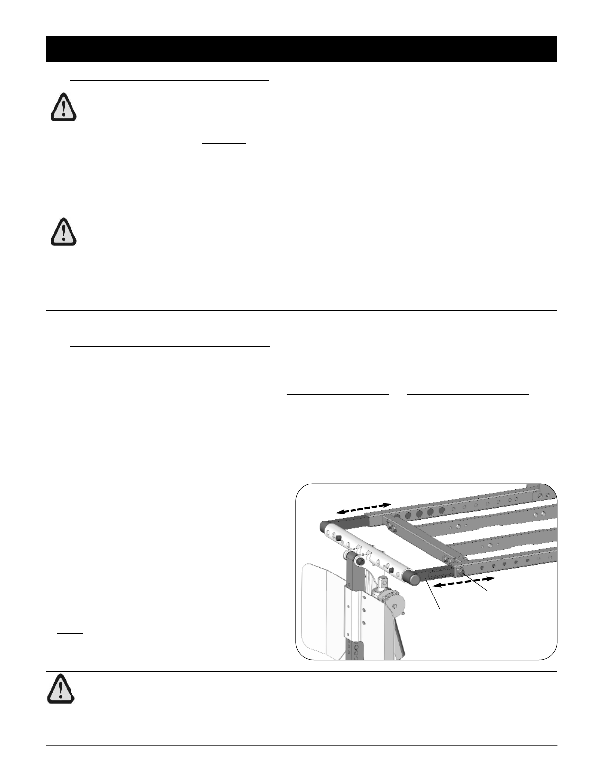
Operating the wheelchair with insufficient ground clearance between the foot platform and
the ground/floor may cause serious injury or property damage.
• While the wheelchair is in motion, ALWAYS maintain a minimum ground clearance of 3 inches, or
the minimum ground clearance stated by wheelchair base manufacture (whichever is greater).
• If necessary, elevate the front rigging or tilt the seat to achieve the proper ground clearance prior
to driving the wheelchair.
• Test to ensure the wheelchair does not dip forward and allow the foot platform to touch the ground
while it is in motion. Make further adjustments when necessary.
WARNING! Risk of injury or damage
• Following any legrest adjustment ALWAYS inspect the wheelchair to ensure the front rigging DOES
NOT interfere with the wheelchair chassis or front casters, and that the foot platform does not collide
with the ground.
- 4 -