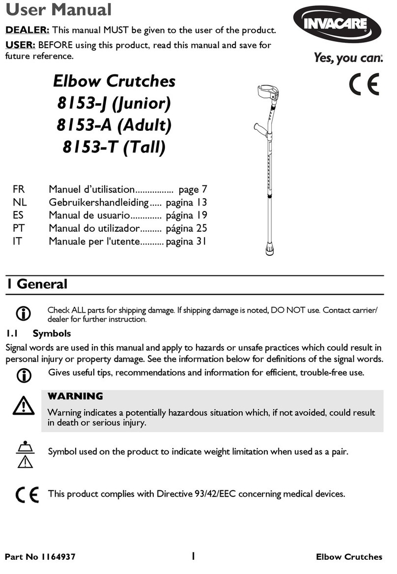
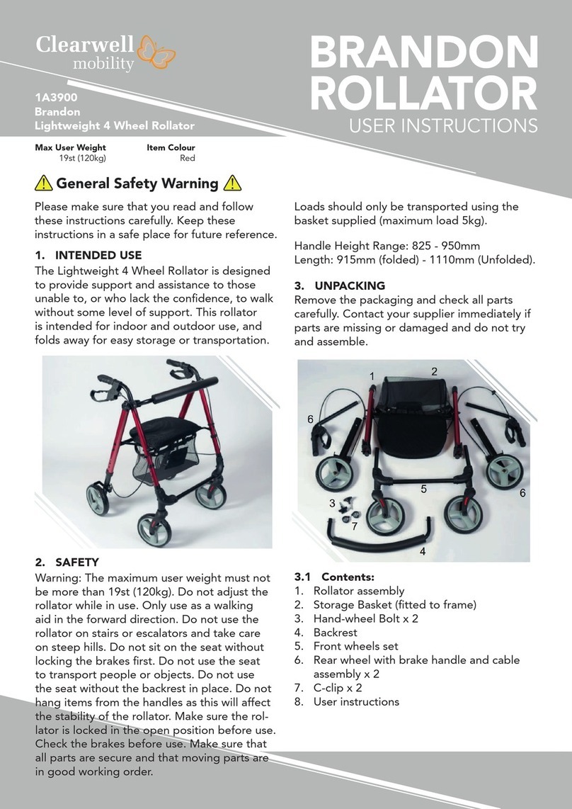
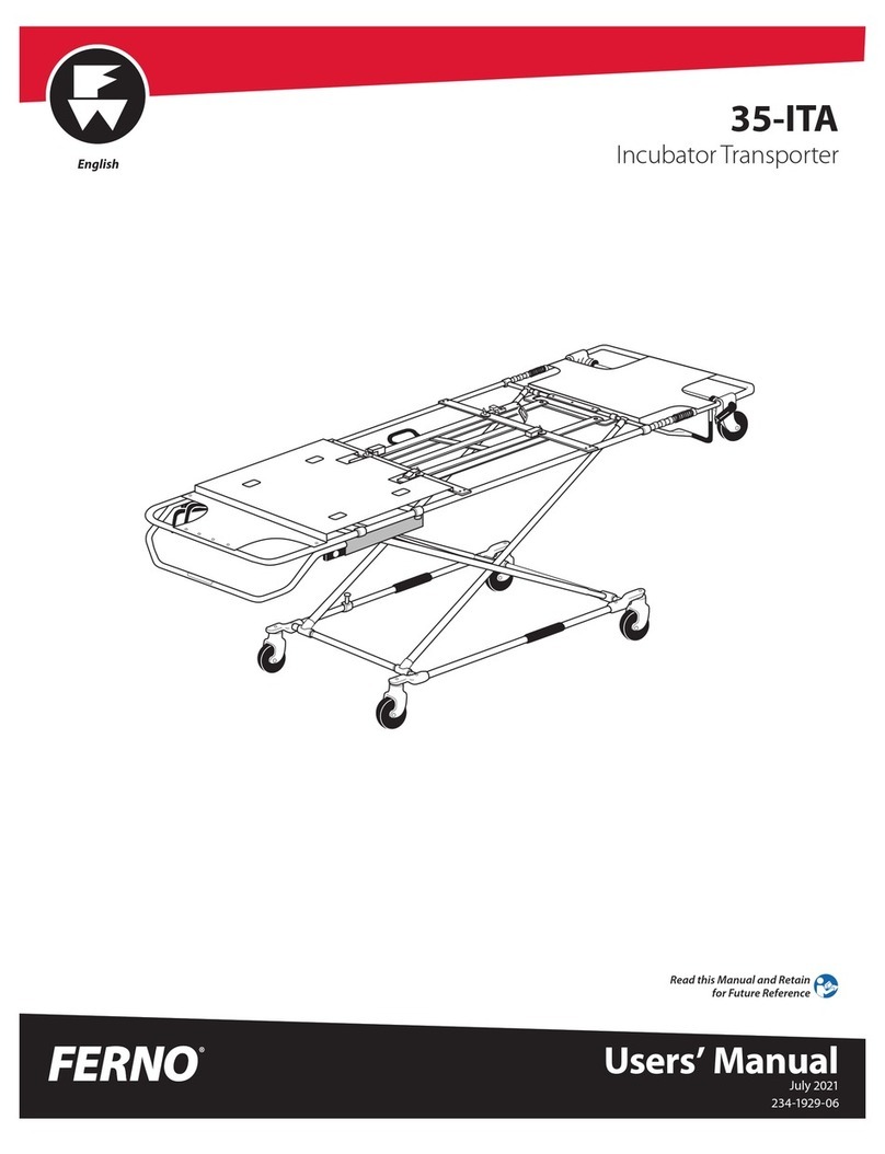
Motion Concepts TRX MAXX PIVOT PLUS LEGREST User manual

TRD0438 Rev D
MAXX PIVOT
PLUS LEGREST
(FOR MANUAL AND POWER LEGREST MODELS)
INSTALLATION/SET-UP MANUAL
DEALER: This manual contains important instructions and safety information related
to the installation, set-up and adjustment of our Maxx Pivot Plus Legrests. These
instructions are for use only by trained /qualified technical personnel

IMPORTANT!
The most important link in the delivery chain is the end
user. The user must be satisfied with the product in terms
of function, safety and aesthetics. No sale is complete
unless the end user receives thorough training in all
aspects of the care and use of the system. A complete
instruction session with your customer is essential.
As a qualified Dealer or Healthcare Professional it is your
responsibility to ensure that the seating system is set up
properly and safely to meet the specific requirements of
the end user.
If you have any questions or concerns regarding the instructions contained in this manual, please
contact our Technical Service Department for assistance.
USA 888-433-6818
CAN 800-680-4191
This manual may not be reproduced or reprinted either partly or completely without previous written consent
from Motion Concepts or its statutory representatives.
This manual is compiled from the latest specifications and product information available at the time of publication.
We reserve the right to make any necessary as they become necessary. Any changes made to our products
may cause slight variations between the illustrations and explanations in this manual and the product you have
purchased. If you have any questions or concerns regarding the information provided in this manual, please
contact our Technical Service Department for assistance.
Motion Concepts LP Copyright © 2020

Safety Symbols:
Safe and proper installation, set-up and adjustment of your Motion Concepts device depends upon your
diligence in following the warnings, cautions and information provided in this Manual.
The symbols below are used throughout all Motion Concepts’ manuals to identify warnings, cautions and
important notes. It is very important for you to read and understand them completely.
CAUTION! Failure to heed the cautions in this Manual may result in damage to your TRx
Power Positioning System.
WARNING! Failure to heed the warnings in this manual may result in personal injury.
Important! Important information to remember when installing your TRx seating system.
Training
Installation and set-up of the Maxx Pivot Plus Center Mount Legrest must only be done by a trained techni-
cian or healthcare professional. If you are not certified as an installer, please arrange immediately for training
by a Motion Concepts technician or sales agent who has been certified to teach the installation and set-up of
the Maxx Pivot Plus Legrest. Every effort will be made to meet your training needs.
Note: Before proceeding with the installation/set-up, ensure that no pages are missing from this manual.
Hardware
Unless otherwise indicated, all the hardware required to complete the installation will be provided by Motion
Concepts. Please refer to the Installation/Assembly Overview Drawing in Section 1.0 to determine the size,
type and configuration of the hardware.
WARNING! Do Not Substitute Hardware
• All hardware used by Motion Concepts in the assembly and installation of our Power Positioning
Systems is high strength. Use only the hardware supplied with your seating system.
Tools
The following tools are required to complete the installation, adjustment & set-up:
•
Imperial and Metric Wrench and/or Socket Set (7/16”, 11mm); Hex Keys: 4mm, 5mm; Standard Screwdriver
Important Information: Before You Begin!
Please refer to Section 2.0 of the Motion Concepts Owner’s Manual (TRD0000) (provided separately) for
detailed safety information related to our Motion Concepts power positioning system and accessories
IMPORTANT! Motion Concepts disclaims all responsibility for any personal injury or damage to property
that occurs as a result of improper or unsafe use of the power positioning system or the wheelchair on
which the system is installed.
General Safety Warnings!
WARNING! Danger of injury if wheelchair and/or power positioning system is used in any
other way than the purpose described in this manual!
• Only ever use the wheelchair/seating system in accordance with the instructions provided in this
Owners Manual and your powerbase Owners/Operators Manual
• Pay strict attention to all safety information provided.
- 3 -

- 4 -
WARNING! Danger of injury by moving parts!
• To avoid personal injury and injury to other individuals from moving wheelchair parts such as wheels,
power legrests, and/or tilt or elevate modules, always be aware of your surroundings, especially when
children are present.
• Pinch points may occur during the operation of your power legrest. Always keep hands and fingers clear
of moving parts to avoid injury.
WARNING! Risk of injury, tipping or damage
• When travelling down a ramp or incline, never attempt to drive with leg rests in the extended position.
WARNING! Any sudden or gradual deterioration in the function/performance of your power
positioning system (i.e. increased actuator motor/gearbox noise, rattling, sloppiness, etc...) must
be reported to your Dealer immediately.
• A complete wheelchair inspection by a qualified technician is recommended to ensure there is no
unusual wear and tear, or physical damage that requires servicing and/or repair.
WARNING! Risk of Injury or damage if correct or improper replacement (service) parts are used
• Replacement parts for your power positioning system MUST match original Motion Concepts parts
WARNING! Danger of accident and loss of guarantee if maintenance is insufficient!
•For reasons of safety and in order to avoid accidents which result from unnoticed wear, it is recommended
that under normal operating conditions your power positioning system undergoes a complete bi-annual
inspection
General Safety Warnings! (...cont’d)
WARNING! ThefollowingguidelinesshouldbeadheredtowhileoperatingyourMotion Concepts
power positioning system to avoid damage or injury and ensure safe operation:
• Never operate the tilt, elevate seat or power elevating legrest function while underneath a fixed object such as
a table or desk.
• Never use the footplates as support during transfers. When transferring in or out of the seating system,
ensure that footplates/foot platforms are in the ‘flipped-up’ or ‘swing-away’ position (where applicable).
• Never exceed the maximum allowable weight capacity for your power positioning system
• Never allow items (i.e.; posture belts, backpacks, coats, etc...) to be trapped under your seat when tilted,
or beneath your power legrests when extended, otherwise damage to the system may occur.
• Never allow your power center mount legrest to be used as a tie-down point in a vehicle. Use only
the designated anchoring points on the power wheelchair.
• Never use you legrest footplates/foot platforms to open doors or move obstructions.
• Never operate your power positioning system while driving your wheelchair.
WARNING! Risk of Serious Injury or Damage
Operating the wheelchair with insufficient ground clearance between the footplates and the
ground/floor may cause serious injury or property damage.
• While the wheelchair is in motion, ALWAYS maintain a minimum ground clearance of 3 inches, or the
minimum ground clearance stated by wheelchair base manufacture (whichever is greater).
• If necessary, elevate the front rigging or tilt the seat to achieve the proper ground clearance prior to driving
the wheelchair.
• Test to ensure the wheelchair does not dip forward and allow the footplates to touch the ground while it is in
motion. Make further adjustments when necessary.
WARNING! Risk of injury or damage
• Following any legrest adjustment ALWAYS inspect the wheelchair to ensure the front rigging DOES NOT
interfere with the wheelchair chassis or front casters, and that the footplates do not collide with the ground.

1.0 Assembly/Overview Drawings
Adjustable Depth Maxx Cam-Lock Legrest Receivers
OFFSET Cam-Lock Receiver
(right receiver shown)
IMPORTANT! Ensure the locking
lever is installed as indicated
BOTH RECEIVERS SHOWN
IN UNLOCKED STATE
STRAIGHT Cam-Lock Receiver
(right receiver shown)
- 5 -

1.0 Assembly/Overview Drawings
- 6 -
Legrest
Mounting Pin
(note: right legrest assembly shown)
Extension Bar
Calf Pad
Mounting Plate
Maxx Pivot Plus MANUAL
Legrest Assembly
Calf Pad
Legrest Shroud
(removable)
Knee-To-Heel (KTH) Adjustment
Manual
Legrest
Adjustment
Lever
Footplate
Assembly
Calf Pad
Latch/Release
Mechanism

- 7 -
Footplate
Assembly
Legrest
Mounting Pin
(note: right legrest assembly shown)
Extension Bar
Calf Pad
Mounting Plate
Maxx Pivot Plus POWER
Legrest Assembly
Calf Pad
Legrest Shroud
(removable)
Knee-To-Heel (KTH) Adjustment
Power
Legrest
Actuator
Calf Pad
Latch/Release
Mechanism
1.0 Assembly/Overview Drawings

2.1 Installing the Maxx Pivot Plus Legrest
Legrest Installation: (Refer to images A, B and C below)
2.1.1 Place the lever handle in the upright (unlocked) position.
2.1.2 Insert the mounting pin into the legrest receiver and lower
the cam lever to lock the legrest into position.
Note: The beveled face of the mounting pin will align with the
cam-lock and secure the Maxx PPL into place.
Maxx Pivot Plus Legrests (Installed)
A.
Locked
Position
Unlocked
Position
B.
Lever
Handle
Mounting
Pin
C.
Lever
Handle
- 8 -
1.0 Assembly/Overview Drawings

2.0 Maxx Pivot Plus Legrest Installation & Set-Up
2.2 Legrest Depth Adjustment
The Maxx style cam-lock legrest receivers are available in straight or offset styles. Each legrest receiver assembly
is designed to provide up to 1.5” (40mm) of independent fore/aft depth adjustment via the slotted channel in the
receiver cover.
Legrest Depth Adjustment
depth
adjustment
Maxx Legrest Receiver
Maxx Legrest Receiver Installation & Adjustment:
Complete the following instructions separately for each
Maxx legrest receiver.
2.2.1. To install/assemble the legrest receiver, insert the
mounting plate inside the receiver cover (A), then slide the
receiver cover overtop of the Maxx side rail.
Note: the receiver cover is installed over the Maxx side rail
and under the seat pan
2.2.2 Install the Maxx legrest receiver into the open-
ing (slot) at the front of the receiver cover, and align the
threaded holes in the legrest receiver with the holes in the
mounting plate.
2.2.3 Secure the mounting plate to the legrest receiver
using the mounting hardware (screws x2) provided (B).
2.2.4 To adjust the depth of the legrest receiver, loosen
both mounting screws and slide the receiver inward/outward
along the slot in the reciever cover (C).
2.2.5 Following any adjustment, always ensure the
mounting screws are fully secure/tighten.
(straight receiver shown)
Receiver Cover
Mounting Plate
B.
A.
Maxx Side Rail
C.
Tools Required: 4mm hex key
- 9 -

WARNING! Risk of Serious Injury or Damage
Operating the wheelchair with insufficient ground clearance between the footplates and the
ground/floor may cause serious injury or property damage.
• While the wheelchair is in motion, ALWAYS maintain a minimum ground clearance of 3 inches, or the
minimum ground clearance stated by wheelchair base manufacture (whichever is greater).
• If necessary, elevate the front rigging or tilt seat to achieve proper ground clearance prior to driving wheelchair.
• Test to ensure the wheelchair does not dip forward and allow the footplates to touch the ground while it is in
motion. Make further adjustments when necessary.
- 10 -
Each legrest extension bar is independently adjustable to accommodate a wide range of knee-to-heel (KTH)
lengths. The set screw slides up and down inside the adjustment slot on the upper legrest housing to allow
infinite KTH adjustment within the slot length. There are four extension bar lengths available to accomodate
a KTH range from 8½” - 20” (22-51cm). The adjustment range for each individual extension bar is as follows:
Short: 8½ -12” (22-31cm), Med: 10 -14” (26-36cm) Long: 13 -17” (33-43cm) X-Long: 16 -20” (41-51cm)
2.3 Legrest Extension Bar: Knee-to-Heel (KTH) Adjustments
Adjusting the KTH Length: (Tools Required: 5mm hex key)
Note: When possible, the client should be seated in the chair during the legrest set-up/ KTH adjustment.
2.3.1. Working on one legrest at a time, loosen the locking clamp assembly so that the legrest extension bar
will slide freely up and down.
2.3.2. Adjust the legrest (extension bar) to the desired KTH Length*, then retighten the clamp assembly to
secure the legrest extension bar into place.
*Note: The final KTH length may be affected by the set-up/angle of the footplates. Additional fine-tune KTH
adjustments may be required following the final footplate set-up. Refer to Section 2.4 for footplate adjustments.
NOTE: Your legrest has been factory pre-assembled using the appropriate length extension bar
needed to achieve the KTH Length requested at the time of order. If at any time you require a
different sized extension bar, please contact our Customer Service Department for assistance
legrest extension bars
Long
Medium
Short
X-Long
set screw
infinite KTH adjustnent
(within slot length)
locking
clamp
(note: shown with
plastic shroud removed)
Actuator, Calf Pad and Footplate are
not shown for illustration purposes
adjutstment
slot
2.0 Maxx Pivot Plus Legrest Installation & Set-Up

- 11 -
FOOTPLATE BOTTOM VIEW
(right legrest shown)
Nylon Set-Screw
Clamping
Block
Adjustable Heel Strap
Our footplates are available in 3 sizes and offer multiple independent adjustments to achieve a wide range of
angles and, depending on the client’s needs. Please refer to Figure 1.0 and the additional images below for
an illustration of the available footplate adjustments.
2.4 Footplate Adjustments
Footplate Adjustments:
Tools Required: 4mm hex key, 7/16” (12mm) wrench, standard screwdriver
2.4.1 By altering the mounting position*of the clamping block (A), the footplate
can be adjusted forward or backward (relative to the legrest extension tube) in
1” (26mm) increments. (*note: the clamping block can also be inverted (rotated
180 degrees), in order to achieve a variation in fore/aft adjustment).
2.4.2 By loosening the clamping block, the entire footplate can be adjusted
inward or outward (in relation to the extension tube) along the pivot bracket
post (B).
2.4.3 The heel strap position can be adjusted front to back as necessary via
mounting holes in the footplate (C); Adjustments are in 1” (26mm) intervals.
2.4.4 The footplate angle (front to back) can be adjusted by loosening the
clamping block and rotating the clamp around the pivot bracket post (D).
2.4.5 The lateral (side-to-side) footplate angle can be adjusted** via the
nylon set-screw located inside the pivot bracket (E). By adjusting the set
screw depth, the footplate angle can be adjusted to achieve an angle greater
than or less than 90 degrees as needed. (**note: set-screw adjustment
requires a standard slot screwdriver).
Pivot
Bracket Footplate (3 sizes)
- Standard
- Large
- X-Large
SIDE VIEW
A
nylon set screw
B
C
D
E
Figure 1.0
inverted
clamp
REAR VIEW
2.0 Maxx Pivot Plus Legrest Installation & Set-Up

Calf Pad
Depth Adjustment
(Total Range=1.5” (38mm))
calf pad
mounting plate 3/4” (19mm) increments
pull the lever
inward to release
the latch and
swing/rotate the
calf pad inward to
allow leg clearance
2.5 Calf Pad Set-Up/Adjustments:
The curved calf pads on the Maxx Legrest offer a full range of independent adjustment to ensure a high level of
comfort for the end user. A lock/release mechanism (lever) allows each calf pad to be swivelled around the
legrest in order to improve leg clearance during transfers in and out of the wheelchair. Refer to Figure 2.0,
along with the additional images/instructions provide below, for a summary of the various calf pad adjustments.
release lever
Swing-Away (Unlatched)
Calf Pad Position
Note: the calf pad will automatically lock into place
when it is returned to its original position.
actuator mount
calf pad
mounting plate
Figure 2.0
calf pad
mounting
bracket
I. Independent Calf Pad Adjustments:
Tools Required: 4mm/5mm hex key
2.5.1. The depth of each calf pad can be adjusted independently, relative to the legrest extension tube. The calf
pad mounting plate can be mounted in one of three optional positions along the calf pad mounting bracket (A).
A
Locked
Calf Pad
Position
- 12 -
2.0 Maxx Pivot Plus Legrest Installation & Set-Up

REAR VIEW
(right calf pad)
Horizontal
Adjustment
Vertical
Adjustment
HEIGHT
ADJUSTMENT
CALF PAD ADJUSTMENTS
BARIATRIC CALF PAD
MOUNTING PLATE (OPTIONAL)
Extended Position
(maximum) Lowered Offset
Raised Offset
Angled
MOUTING BRACKET ADJUSTMENTS (SAMPLE CONFIGURATIONS)
Centered
2.5.4. The calf pads may be adjusted independently on their respective mounting plate using the hardware at
the rear of the calf pads. Calf pads can be adjusted (for depth, height and angle) to achieve a variety of different
configurations. Refer to sample configurations illustrated below.
II. Calf Pad Mounting Plate Adjustments:
2.5.2. Altering the mounting position of the calf pad mounting plate on the actuator mount, will adjust the height
of the calf pad up or down relative to the footplate (B).
2.5.3. By changing the screw/slot positions in the mounting bracket, and/or by changing the mounting hole
locations on the calf pad itself, each pad can be independently adjusted to meet the specific needs of the end user
(C). (See also Calf Pad Mounting Bracket Adjustments below)
B
C
If you have any questions or concerns regarding the programming instructions contained in this manual,
please contact our Technical Service Department for assistance.
USA 888-433-6818
CAN 800-680-4191
- 13 -
2.0 Maxx Pivot Plus Legrest Installation & Set-Up

NOTES:


USA
700 Ensminger Rd. Suite 112
Tonawanda, NY, USA 14150
716-447-0050
888-433-6818
Canada
84 Citation Dr. Units 1-3
Concord, Ontario,
Canada L4K 1C9
905-695-0134
www.motionconcepts.com
Table of contents
Other Motion Concepts Mobility Aid manuals