Motoalliance 46'' Garden Tractor Plow System User manual

Thank you for purchasing the MotoAlliance’s Lawn Tractor Plow System by MotoAlliance! Fully
engineered in the USA.
Warning And User Caution
- Never allow passengers to ride on the blade while plowing
- Stay clear of bystanders while plowing
- Do not exceed 10 MPH with blade installed
- Always wear safety gear (helmet, glasses, etc) when plowing
- Always put your vehicle in Park before changing the angle of the plow blade
- Use extreme caution when plowing and riding on sloped surfaces
- Avoid all fixed objects and always wear a seatbelt
- Be cautious of the blade when lowering it from an upright position
- Always store your blade resting on the ground
Maintenance:
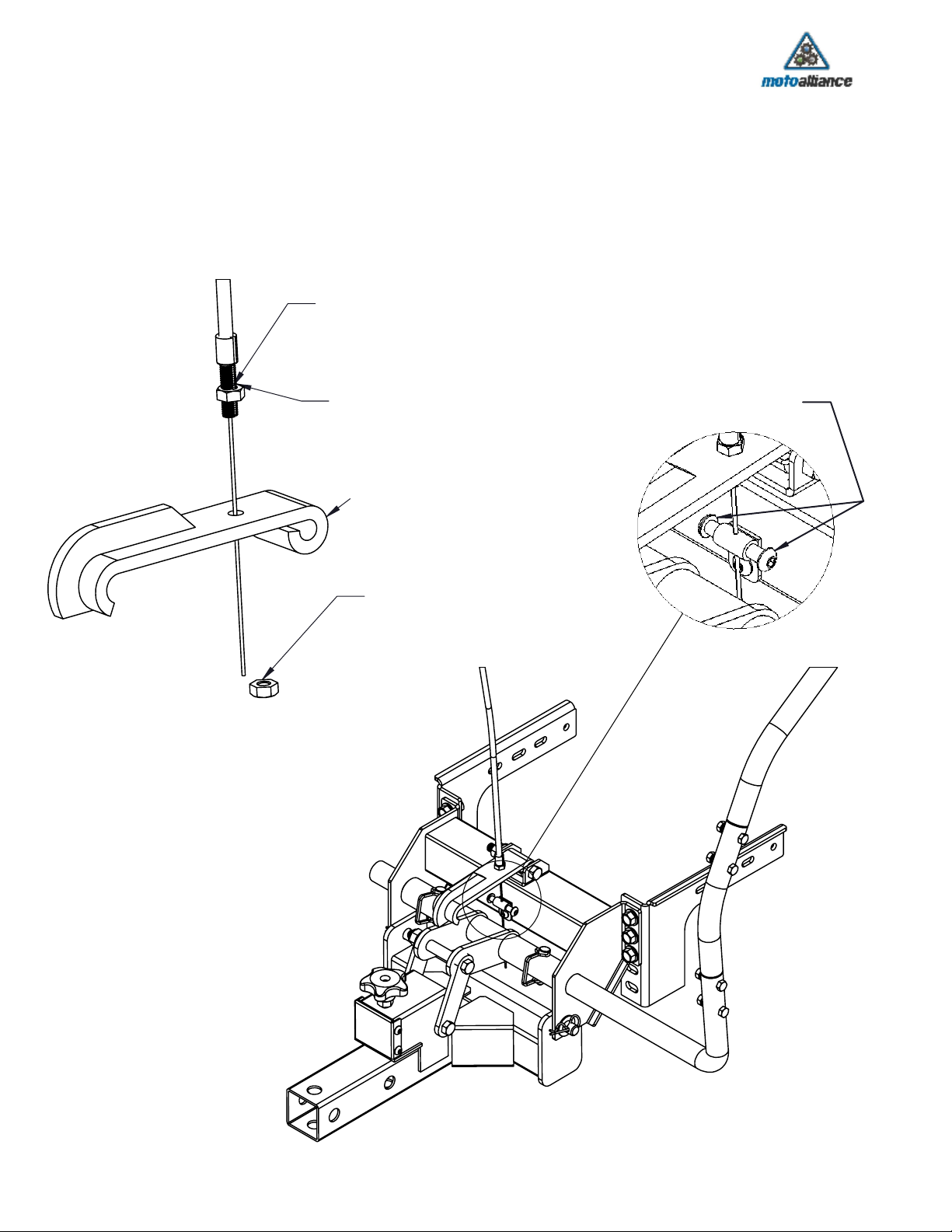
It is recommended to check all hardware on the Lift System from time to tim. Loose or worn
hardware could cause severe damage to the lift and plow system, or injury to the operator in
the event of component failure.
Some degree of paint scratching or chipping is inevitable during the plowing season. We recommend
purchasing a rust preventing paint at the end of the season to be applied per the manufacturer's
recomendation on areas of exposed metal.
Long Distance Travel:
When transporting long distances (1/4 mile or more) it is receommended to secure the plow blade to
the lawn mower with a rachet strap to prevent the plow blade from bouncing and causing potential
damage to the lawn mower or lift system.
23001 Industrial Blvd, Rogers, MN 55374
1-866-527-7637 (toll free)
www.motoalliance.com / [email protected]
1
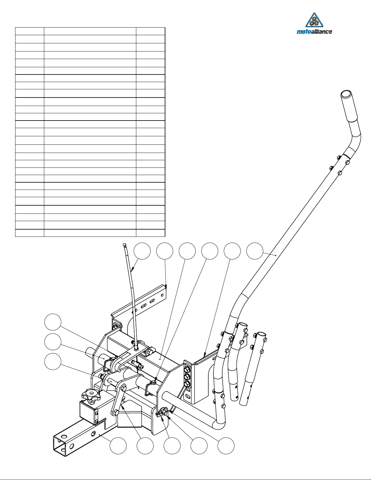
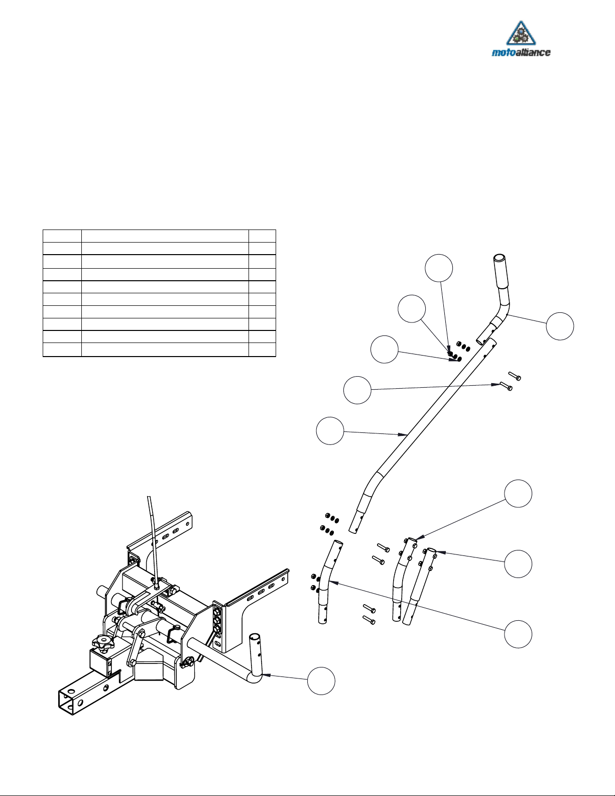
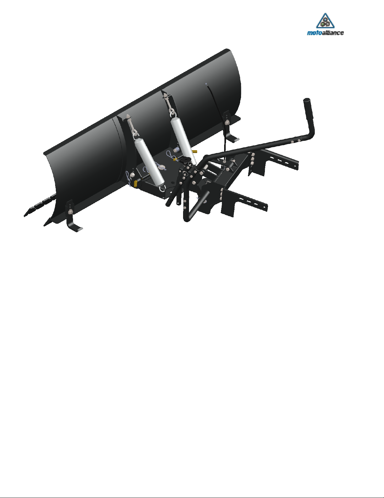
46" Garden Tractor Plow System

412 98
2 6 251126
151
General Lift System Components Diagram
5
7
10
ITEM NO.
DESCRIPTION
QTY.
1
Main Mounting Assembly
1
2
Accessory Attachment Frame
1
3
Cable Attachment Bracket
1
4
Lift Handle Assembly
1
5
Lift Bracket
1
6
Lift Arm Link
2
7
Latch Bracket
1
8
Cable Assembly
1
9
Side Plate Right
1
10
Latch Sleeve
1
11
Tilt Pin
1
12
Side Plate Left
1
13
Latch Torsion Spring (Not Shown)
1
14
3/8-16 Nylock Nut
2
15
5/16 Dia. with Keeper Clip
2
16
HBOLT 0.3750-16x3.5x1-S
2
17
HBOLT 0.3750-16x2.75x1-S
1
18
HNUT 0.3750-16-D-N
7
19
3/8" Star Washer
6
20
IN-HWMS 0.375-16x0.75x0.75-S
12
21
Narrow FW 0.375
2
22
Regular FW 0.375
1
23
Regular LW 0.375
1
24
SBHCSCREW 0.25-20x0.5-HX-N
3
25
R-Pin Retainer Clip
2
26
1/2" Washer
2
23001 Industrial Blvd, Rogers, MN 55374
1-866-527-7637 (toll free)
www.motoalliance.com / [email protected]
2

50
55
106
53
52
103
56
51
Insert Plunger Rod #51
from under side.
D
Compress Spring #52, and place 3/8"
washer #53 below spring while
inserting into opening. Push Plunger
Rod thru bottom and out top hole.
Secure Cover Plate
with provided hardware.
Secure Knob #56, to Plunger Rod #51, with
M10 Nut #103. Tighten #56 and #103 against
each other to prevent the knob from coming
loose.
Plunger must move freely up and down once
secured and tightened.
Assembling of the Accessory Attachment Component
( preassembled in the factory; for reference only.
ITEM NO.
DESCRIPTION
QTY.
50
Accessory Attachment Weldment
1
51
Plunger Rod
1
52
Plunger Spring
1
55
Plunger Cover Plate
1
53
Regular FW 0.375
1
103
B18.2.4.2M - Hex nut, Style 2, M10 x
1.5, with 16mm WAF --D-S
1
56
Five Arm Knob Threaded Through
Hole M10 internal
1
106
M6 Screw
4
23001 Industrial Blvd, Rogers, MN 55374
1-866-527-7637 (toll free)
www.motoalliance.com / [email protected]
3

Tilt Pin
Handle Base
Plow Side - Lift Assembly
Mower Side - Lift Assembly
Lift Bracket
R-Clip
1/2" Flat Washer
Tilt Pin
Installation of the Handle Base.
Parts Required: (1) Plow Side - Lift Assembly
Pre Assembled,
(1) Mower Side Lift Assembly
Pre Assembled
, (2) 1/2" Flat Washers, (2) R-Clips, (1) Tilt Pin,
(1) Handle Base.
Align Holes in Plow Side - Lift Assembly with Holes in Mower Side - Lift Assembly. Slide Tilt Pin thru lower holes and secure on other side with (1)
1.
1/2" Flat Washer and (1) R-Clip.
Now, Align the Lift Bracket component with the holes as shown in diagram below. Once aligned, slide Handle Base thru entire assembly and align
2.
holes in both components.
Secure with (2) 5/16" Lynch Pins.
3.
23001 Industrial Blvd, Rogers, MN 55374
1-866-527-7637 (toll free)
www.motoalliance.com / [email protected]
4

J
These slots and hole are used to secure the
"46" Lawn Tractor Lift System" to your specific
Lawn Tractor.
Depending on the specific Lawn Tractor
different hardware and hole/slot locations may
be required to be used.
Note:
It may be necessary to remove Heat Shields, Accessory Bumper
or other aftermarket acceessories prior to installation of the lift system.
Special Note:
As with most of the assembly steps in this manual, please do not tighten any hardware until all components have been assembled and
secured to the Lawn Tractor. Finger tight will suffice for most of the assembly steps until all assembly has been completed. Once complete,
tighten the listed hardware in the step.
3/8" Hex Nut
3/8"Star Washer
3/8" Hex/Washer Bolt
3.50" - 4.00"
Is the Ideal Mounting
Height off of ground.
Varies Depending
on Make and Model
37 3839 40
41
42
44
43
Assembling the Support Brackets to Lawn Tractor
ITEM NO.
DESCRIPTION
QTY.
37
HBOLT 0.3125-18x1x0.875-S
4
38
Narrow FW 0.3125
4
39
Regular LW 0.3125
4
40
HNUT 5/16-18
4
41
HBOLT 0.2500-20x1x0.75-S
4
42
Narrow FW 0.25
4
43
HNUT 1/4-20
4
44
Regular LW 0.25
4
23001 Industrial Blvd, Rogers, MN 55374
1-866-527-7637 (toll free)
www.motoalliance.com / [email protected]
5

29
29
31
30
28
32
33
35
34
Please Note:
The 46" Lawn Tractor Lift System has been designed to fit many different makes and models of Lawn Tractors.
Based on the make and model this system is being installed on, we recommend final handle assembly step is done last.
We have provided extra Handle Tubes to provide flexibility in the position and location of the Handle to the rider and easy
access to the varying potential rider positions. We suggest you do not fully assemble all hardware into the Handle Tubes
until the ideal position has been determined by the user. Once this has been determined, then install and tighten all
hardware.
27
Assembling the Handle Assembly
ITEM NO.
DESCRIPTION
QTY.
27
Handle Base
1
28
Handle With Cap
1
29
Handle Tube 1
2
30
Handle Tube 2
1
31
Handle Tube 3
1
32
HBOLT 0.2500-20x1.375x0.75-N
10
33
HNUT 0.2500-20-D-N
10
34
Narrow FW 0.25
10
35
Regular LW 0.25
10
23001 Industrial Blvd, Rogers, MN 55374
1-866-527-7637 (toll free)
www.motoalliance.com / [email protected]
6

Fig 3
Fig 5
Fig 2
Fig 4
Fig 2.
Swivel Plate
Trip Spring
Fig 3.
Fig 5.
Fig 4.
Fig 2
Fig 4
S
3/8" Hex Nut
3/8" Flat Washer
3/8" Eye Bolt
3/8" Hex Nut
3/8" Flat Washer
Blade Stop Collar
3/8" x 1.50" Hex Bolt
Attaching Trip Springs and Eye Bolts to Plow Blade
Proceed with securing the Trip Springs and Eye Bolts to Blade Assembly.
Parts Required - (4) 3/8" Hex Nuts, (4) 3/8" Flat Washers, (2) Trip Springs, Plow Assembly
Pre Assembled
.
Insert (1) 3/8" Hex nut and (1) 3/8" Flat Washer each eye bolt as shown (Fig 1)
1.
Hook spring as shown onto the main Swivel Plate of the Plow Assembly (Fig 2)
2.
Hook other end of Trip Spring onto the end of the Eye Bolt (Fig 3)
3.
Once Trip Spring is hooked onto Eye Bolt, Slide threaded end of Eye Bolt thru hole in Blade
4.
Assembly and secure with 3/8" Washer and 3/8" Hex Nut.
Fig 5 - Secure Blade Stop Collar with (1) 3/8-16 x 1.50" Hex Bolt and (1) 3/8" Nylock Nut. Repeat for
5.
other side.
Fig 1.
23001 Industrial Blvd, Rogers, MN 55374
1-866-527-7637 (toll free)
www.motoalliance.com / [email protected]
7

Dirt Blade Wear Bar
Snow Plow Wear Bar
F
3/8" x 1.25" Carriage Bolt (9X)
3/8-16 Nylock Nut (9X)
Assembling the Wear Bar to the Main Plow Blade
For Shipping purposes, the Snow and Dirt Wear Bars have been installed onto the
Main Plow Blade in the factory. This reduces the possibility of damage to packaging or
other Lift System components.
Depending on the end users preference and desired use for the plow, it will required
you to remove the Wear Bar attachment hardware and remove the wear bar that you
are not intending to use. Once this is completed, reassemble with the hardware
removed prior, to secure wear bar of your choice.
23001 Industrial Blvd, Rogers, MN 55374
1-866-527-7637 (toll free)
www.motoalliance.com / [email protected]
8

Assembling the Plow Assembly to the Lift System
Fig 2.
N
Pull up on Release Knob
to allow Plow Assembly to slide into place
Insert Pivot Pin from bottom
Secure with 5/8" Washer and R-Clip
Fig3.
At this point you are ready to secure the Plow Blade to the Lift System mounted to the Lawn Tractor.
Parts Required: (1) 5/8" Dia. x 2.75" Pivot Pin, (1) 5/8" Flat Washer, (1) R-Clip Retainer.
Carefully slide blade assembly over the Lift System forward face hitch tube (Fig 1)
1.
Pull Up on Release Knob and continue to slide Plow Blade over hitch tube until holes align in both (Fig 2)
2.
Once holes are aligned, slide the Pivot Pin thru bottom side of aligned holes and secure with 5/8" Washer and R-Clip on top (fig 3)
3.
Fig 1.
23001 Industrial Blvd, Rogers, MN 55374
1-866-527-7637 (toll free)
www.motoalliance.com / [email protected]
9

Cable Socket
1/4-20 Hex Nut
Latch Bracket
1/4-20 Hex Nut
Tighten these to screws
Adjusting the Lift Latch:
Depending on the application, final adjustments to the Latch Bracket are made once the
Plow Blade has been secured and all hardware has been checked and confirmed to be
tight.
It is desired to adjust the latch cable so that the Latch Bracket sits just above the main lift
assembly in a normal raised position. To adjust this, make sure cable is loose in the
bracket.
23001 Industrial Blvd, Rogers, MN 55374
1-866-527-7637 (toll free)
www.motoalliance.com / [email protected]
10

Dirt or Snow Applications.
Removal of these Pins will allow the blade to "Trip" in the event of the blade coming in
contact with an object that could cause damage to the Lift System or Lawn Tractor.
In Dirt moving applications, the pins can be used in place.
In Snow Plowing applications, it is recommended to remove these pins from both sides.
Depending on the end users prefference, this blade can be used in either a
fixed position or with the ability to allow the blade to "Trip" in the event the
blade comes in contact with something that could damage the Lift System
or the Lawn Tractor.
23001 Industrial Blvd, Rogers, MN 55374
1-866-527-7637 (toll free)
www.motoalliance.com / [email protected]
11

Cable Lever & Hardware
All Hardware necessary to secure the Cable Lever will be packaged together.
Back Side Bracket
Back Side Bracket
Lever Assembly
Machine Screw
Hex Nut
Cable Lever can be located on either the front
or the back side of the handle depending on
the users preference.
Lever Assembly
23001 Industrial Blvd, Rogers, MN 55374
1-866-527-7637 (toll free)
www.motoalliance.com / [email protected]
12

WARRANTY CLAIMS:
You must request a warranty evaluation before sending products in to MotoAlliance. Do this by filling out the form available on
1.
www.motoalliance.com a Tech Support: Warranty Request Form.
You must provide MotoAlliance with an order number and date of purchase acceptable to MotoAlliance.
2.
This warranty does not cover the removal or re-installation of the winch, or any 3rd party labor expense.
3.
MotoAlliance will, at its option, repair, replace, or refund the purchase price of a defective winch or component, provided you return the
4.
defective winch or component during the warranty period.
You are responsible for all charges related to shipping the product to MotoAlliance. MotoAlliance will return ship for free within the
5.
contiguous USA, but will charge for return shipping to customers in HI, AK, and those outside of the USA.
Upon receiving the product, MotoAlliance technicians will evaluate the winch for signs of misuse or abuse and make a determination for an
6.
appropriate course of action as outlined in #4 above. MotoAlliance technicians reserve the right to determine if such abuse occurred and
can, at their discretion, void the warranty.
If warranty parts are required, MotoAlliance may send replacement parts free of charge to owners in the US and Canada. Other international
locations will be required to pay for shipping charges on those parts. If in-person diagnosis is required, the owner is responsible for shipping
charges connected to getting the product to MotoAlliance. If the damage is covered under the warranty outlined above, MotoAlliance will cover the
cost of repair and return shipping charges. If it is not covered by the warranty, the repair charges and return shipping will be the responsibility of the
owner. Typical service time would be three (3) weeks from receipt of returned item by MotoAlliance to receipt of item to owner.
To the fullest extent permitted by applicable law, the following are hereby excluded and disclaimed:
All warranties of fitness for a particular purpose
1.
All warranties of merchantability
2.
All claims for consequential or incidental damages
3.
There are no warranties that extend beyond the description outlined above.
Some states do not allow the above exclusions or disclaimers in consumer transactions and as such this disclaimer/exclusion may not apply to your
particular case. To the extent such warranties of applicability for a particular purpose or merchantability are deemed to apply to this product, they
exist only for so long as the express limited warranty elsewhere set forth is in existence.
MotoAlliance reserves the right to improve any product through changes in design or materials as desired without being obligated to incorporate
such changes in products of previous manufacture. The stated warranty will not cover bills for service, labor or other expenses which have been
incurred by the buyer. This warranty gives you specific legal rights and you may also have other legal rights which vary from state-to-state.
All warranty claims are based on initial invoice date. A copy of initial invoice will be required with any warranty request. Please call 866-527-7637
(toll free) with any warranty related service requests.
LIABILITY DISCLAIMER:
There are inherent risks involved in using any product, including but not limited to: serious physical injury and possible death. MotoAlliance products
are to be used by experienced adults over 18 years of age only. The Seller will not be held liable under any circumstance for incidental or
consequential loss or damage or injury, due directly or indirectly to the use of MotoAlliance products, including any malfunction from negligence or
defect. The Seller makes no claims as to the suitability of MotoAlliance products for any specific purpose or use. Buyer understands that the use of
MotoAlliance products can cause injury or death to themselves or others. The Buyer holds our company and its agents and affiliates harmless from
any liability arising out of or relating to the use or ownership of any MotoAlliance product. Buyer fully accepts responsibility and releases the seller
for all and any personal injuries, fatal injuries, any losses, costs, and damages incurred as a result of Buyer or anyone else operating MotoAlliance
products. Once Buyer submits payment, this will serve as a Purchase Agreement thus releasing Seller of any and all responsibilities of items such
as stated above. By purchasing a MotoAlliance product, you acknowledge that you have read, understand and agree to the terms and conditions of
this Agreement; you also represent that you are of legal age (age 18 years or older) to enter this Agreement and become bound by its terms.
Warranty and Limitations:
MotoAlliance offers a limited two (2) year warranty for each new plow against manufacturing defects in workmanship and materials. Exterior parts
and finish are warranted against defects in original workmanship and materials. No warranty applies to exterior finish after initial use. The entire
warranty is void if the plow is used in commercial/industrial applications.
Wear Bars and Skid feet are considered wearable parts and are warranted against defects in original workmanship and materials. No warranty
applies to wearable parts after initial use.
The obligation under this warranty, statutory or otherwise, is limited to the replacement or repair of such part as shall appear to the manufacturer,
upon inspection of such part, to have been defective in material or workmanship. This warranty does not obligate MotoAlliance to bear the cost of
shipping charges in connection with the replacement or repair of defective parts, nor shall it apply to a product upon which repairs or alterations
have been made, unless authorized by MotoAlliance, or for equipment misused, neglected, or improperly installed.
23001 Industrial Blvd, Rogers, MN 55374
1-866-527-7637 (toll free)
www.motoalliance.com / [email protected]
13
Table of contents
Popular Tractor Accessories manuals by other brands

Spearhead
Spearhead TWIGA CLASSIC S51 Handbook

brent
brent THE GRAIN TRAIN 740 Operator's Manual/Parts Catalog

EPI
EPI ENVIRO Cover Deployer 800 Operation and service manual

Bercomac
Bercomac 700277-2 owner's manual

Toro
Toro 04479 Operator's manual

Buyers Products Company
Buyers Products Company PW22 Pro-Wings installation instructions