Setting up the DVM
NOTE: DVM setup should occur after Step 8 of MotoCrane Power Supply Unit (PSU)
setup. See ULTRA Operation Manual for more information.
1. Secure the DVM in a location where the module is clearly visible, but does not
impede their ability to safely operate the vehicle.
2. The mounting hardware used to secure the DVM must not be prone to
loosening, sagging, or any changes in location/orientation which could cause
the DVM to become unsafe to drivers and/or passengers during operation.
3. With the MotoCrane PSU MAIN power switch in the “OFF” position, connect
the 15’ Aux Cable provided to the AUX connector on the PSU, and then to the
AUX connector on the DVM.
4. The MotoCrane PSU MAIN Power Switch can now be turned on. This will
connect power to both ULTRA and the DVM.
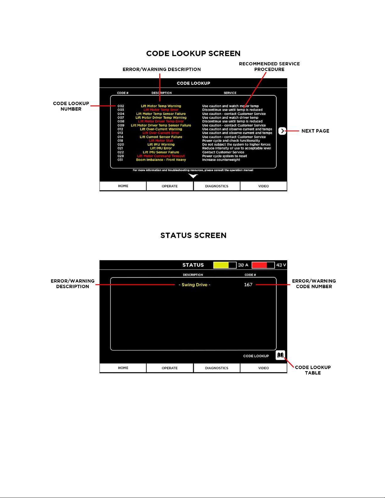
Using the DVM
NOTE: The DVM is a read-only device, meaning it is used to monitor the status of
ULTRA, but not make configurations. The DVM allows the user to monitor arm position,
battery voltage, system current, diagnostic messages, and much more. Navigation of
the DVM is identical to the MotoCrane Controller, with optimizations made to graphics
for maximizing important information “at-a-glance.”
1. For monitoring ULTRA arm position, use the OPERATE page. Arm position will
appear exactly as it has been configured for the MotoCrane Controller.
2. For monitoring ULTRA numerically, use the DIAGNOSTICS page.
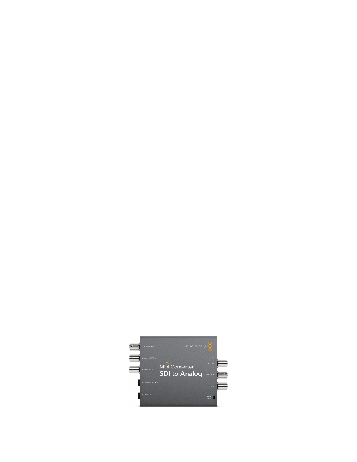
3. For monitoring a NTSC witness/FPV camera input via the NTSC BNC port, use
the VIDEO page. If using an HD-SDI input, you can use a converter like the unit
below for converting to the compatible NTSC format.
7